2. Multicast
This chapter provides information about Protocol Independent Multicast (PIM).
2.1. Overview of Multicast
IP multicast is a method of many-to-many communication that simplifies the delivery of unicast datagrams. In the case of unicast delivery, IP packets are sent from a single source to a single recipient. The source inserts the address of the target host in the IP header destination field of an IP datagram, and intermediate routers (if present) forward the datagram toward the target in accordance with their respective routing tables.
However, some applications, such as audio or video streaming broadcasts, require the delivery of individual IP packets to multiple destinations. In such applications, multicast is used to distribute datagrams sourced from one or more hosts to a set of receivers that may be distributed over different (sub) networks. The delivery of multicast datagrams is significantly more complex.
Multicast sources can send a single copy of data using a single address for the entire group of recipients. The routers between the source and recipients route the data using the group address route. Multicast packets are delivered to a multicast group. A multicast group specifies a set of recipients who are interested in a particular data stream and is represented by an IP address from a specified range. Data addressed to the IP address is forwarded to the members of the group. A source host sends data to a multicast group by specifying the multicast group address in the datagram destination IP address. A source does not have to register to send data to a group, nor does it need to be a member of the group.
Routers and Layer 3 (L3) switches use the Internet Group Management Protocol (IGMP) to manage membership for a multicast session. When a host needs to receive one or more multicast sessions, it signals its local router by sending a join message to each multicast group it needs to join. When a host needs to leave a multicast group, it sends a leave message.
To extend multicast to the Internet, the multicast backbone (Mbone) is used. The Mbone is layered on top of portions of the Internet. These portions, or islands, are interconnected using tunnels. The tunnels allow multicast traffic to pass between the multicast-capable portions of the Internet. As more and more routers in the Internet are multicast-capable (and scalable), the unicast and multicast routing table will converge.
The original Mbone was based on the Distance Vector Multicast Routing Protocol (DVMRP) and was very limited. The Mbone is, however, converging around the following protocol set:
- IGMP
- Protocol Independent Multicast (Sparse Mode) (PIM-SM)
2.1.1. Multicast Models (SSM)
This section provides information about the Source-Specific Multicast (SSM) model.
2.1.1.1. SSM
The SSM service model defines a channel identified by an (S,G) pair, where S is a source address and G is an SSM destination address. In contrast to the ASM model, SSM only provides network-layer support for one-to-many delivery.
The SSM service model attempts to alleviate the following deployment problems.
- address allocationSSM defines channels on a per-source basis. For example, the channel (S1,G) is distinct from the channel (S2,G), where S1 and S2 are source addresses, and G is an SSM destination address. This averts the problem of global allocation of SSM destination addresses and makes each source independently responsible for resolving address collisions for the various channels it creates.
- access controlSSM provides an efficient solution to the access control problem. When a receiver subscribes to an (S,G) channel, it receives data sent only by the source S. In contrast, any host can transmit to an ASM host group. At the same time, when a sender picks a channel (S,G) to transmit on, it is automatically ensured that no other sender will be transmitting on the same channel (except in the case of malicious acts such as address spoofing). This makes it harder to spam an SSM channel than an ASM multicast group.
- handling of well-known sourcesSSM requires only source-based forwarding trees. This eliminates the need for a shared tree infrastructure. In terms of the IGMP and PIM-SM, this implies that neither the RP-based shared tree infrastructure of PIM-SM nor the MSDP protocol is required. Therefore, the complexity of the multicast routing infrastructure for SSM is low, making it viable for immediate deployment.
- handling point-to-point applicationsAnticipating that point-to-multipoint applications such as Internet TV will be significant in the future; the SSM model is better suited for such applications.
2.2. Multicast Features
This section contains information about the multicast protocols rewired to support a Nokia router in the network.
2.2.1. IGMP
IGMP is used by IPv4 hosts and routers to report their IP multicast group memberships to neighboring multicast routers. A multicast router keeps a list of multicast group memberships for each attached network, and a timer for each membership.
Multicast group memberships include at least one member of a multicast group on an attached network. In each of its attached networks, a multicast router can assume one of two roles: querier or non-querier. There is typically only one querier per physical network.
The querier issues two types of queries: a general query and a group-specific query. General queries are issued to solicit membership information with regard to any multicast group. Group-specific queries are issued when a router receives a leave message from the node it perceives as being the last remaining group member on that network segment.
If the host needs to receive a multicast session issue and a multicast group membership report, the reports must be sent to all multicast-enabled routers.
2.2.1.1. IGMP Versions and Interoperability Requirements
If routers run different versions of IGMP, they negotiate the lowest common version of IGMP that is supported on their subnet and operate in that version. Three versions of IGMP are supported.
Version 1 — Specified in RFC-1112, Host extensions for IP Multicasting was the first widely deployed version and the first version to become an Internet standard.
Version 2 — Specified in RFC-2236, Internet Group Management Protocol added support for “low leave latency”, that is, a reduction in the time it takes for a multicast router to learn that there are no longer any members of a particular group present on an attached network.
Version 3 — Specified in RFC-3376, Internet Group Management Protocol added support for source filtering, that is, the ability for a system to report interest in receiving packets only from specific source addresses, as required to support SSM, or from all but specific source addresses, sent to a particular multicast address.
IGMPv3 must keep track of the state of each group for each attached network. The group state consists of a filter-mode, a list of sources, and various timers. For each attached network running IGMP, a multicast router records the desired reception state for that network.
2.2.1.2. IGMP Version Transition
Nokia routers are capable of interoperating with routers and hosts running IGMPv1, IGMPv2, and/or IGMPv3. RFC 5186, Internet Group Management Protocol Version 3 (IGMPv3)/Multicast Listener Discovery Version 2 (MLDv2) and Multicast Routing Protocol Interaction explores the interoperability issues and how they affect the routing protocols.
IGMPv3 specifies that if a router receives an earlier version query message on an interface, it must immediately switch to a mode that is compatible with the earlier version. Because the previous versions of IGMP are not source-aware, should this occur and the interface switches to version 1 or 2 compatibility mode, any previously learned group memberships with specific sources (learned via the IGMPv3-specific INCLUDE or EXCLUDE mechanisms) must be converted to non-source specific group memberships. The routing protocol will then treat the query as if there is no EXCLUDE definition present.
2.2.1.3. SSM Groups
IGMPv3 permits a receiver to join a group and specify that it only needs to receive traffic for a group if that traffic comes from a particular source. If a receiver does this, and no other receiver on the LAN requires all the traffic for the group, the designated router (DR) can omit performing a (*,G) join to set up the shared tree, and instead issue a source-specific (S,G) join only.
The range of multicast addresses from 232.0.0.0 to 232.255.255.255 is currently set aside for source-specific multicast in IPv4. For groups in this range, receivers should only issue source-specific IGMPv3 joins. If a PIM router receives a non-source-specific join for a group in this range, it should ignore it.
A Nokia PIM router must silently ignore a received (*,G) PIM join message where G is a multicast group address from the multicast address group range that has been explicitly configured for SSM. This occurrence should generate an event. If configured, the IGMPv2 request can be translated into IGMPv3. The router allows for the conversion of an IGMPv2 (*,G) request into a IGMPv3 (S,G) request based on manual entries. A maximum of 32 SSM ranges is supported.
IGMPv3 also permits a receiver to join a group and specify that it only needs to receive traffic for a group if that traffic does not come from a specific source or sources. In this case, the DR will perform a (*,G) join as normal, but can combine this with a prune for each of the sources the receiver does not wish to receive.
2.2.2. PIM-SM
PIM-SM leverages the unicast routing protocols that are used to create the unicast routing table, OSPF, IS-IS, BGP, and static routes. Because PIM uses this unicast routing information to perform the multicast forwarding function, it is effectively IP protocol independent. Unlike DVMRP, PIM does not send multicast routing table updates to its neighbors.
PIM-SM uses the unicast routing table to perform the Reverse Path Forwarding (RPF) check function instead of building up a completely independent multicast routing table.
PIM-SM only forwards data to network segments with active receivers that have explicitly requested the multicast group. PIM-SM in the ASM model initially uses a shared tree to distribute information about active sources. Depending on the configuration options, the traffic can remain on the shared tree or switch over to an optimized source distribution tree. As multicast traffic starts to flow down the shared tree, routers along the path determine whether there is a better path to the source. If a more direct path exists, the router closest to the receiver sends a join message toward the source and reroutes the traffic along this path.
PIM-SM relies on an underlying topology-gathering protocol to populate a routing table with routes. The routing table is called the Multicast Routing Information Base (MRIB). The routes in this table can be taken directly from the unicast routing table, or they can be different and provided by a separate routing protocol such as MBGP. Regardless of how it is created, the primary role of the MRIB in the PIM-SM protocol is to provide the next hop router along a multicast-capable path to each destination subnet. The MRIB is used to determine the next hop neighbor to whom any PIM join/prune message is sent. Data flows along the reverse path of the join messages. In contrast to the unicast RIB that specifies the next hop that a data packet would take to get to a subnet, the MRIB gives reverse-path information and indicates the path that a multicast data packet would take from its origin subnet to the router that has the MRIB.
2.2.2.1. PIM-SM Functions
2.2.2.1.1. Phase One
In this phase, a multicast receiver expresses its interest in receiving traffic destined for a multicast group. Typically, it does this using IGMP or MLD, but other mechanisms can also serve this purpose. One of the receiver’s local routers is elected as the DR for that subnet. When the expression of interest is received, the DR sends a PIM join message toward the RP for that multicast group. This join message is known as a (*,G) join because it joins group G for all sources to that group. The (*,G) join travels hop-by-hop toward the RP for the group, and in each router it passes through the multicast tree state for group G is instantiated. Eventually, the (*,G) join either reaches the RP or reaches a router that already has the (*,G) join state for that group.
When many receivers join the group, their join messages converge on the RP and form a distribution tree for group G that is rooted at the RP. This is known as the RP tree and is also known as the shared tree because it is shared by all sources sending to that group. Join messages are resent periodically as long as the receiver remains in the group. When all receivers on a leaf-network leave the group, the DR sends a PIM (*,G) prune message toward the RP for that multicast group. However, if the prune message is not sent for any reason, the state will eventually time out.
A multicast data sender starts sending data destined for a multicast group. The sender’s local router (the DR) takes those data packets, unicast-encapsulates them, and sends them directly to the RP. The RP receives these encapsulated data packets, de-encapsulates them, and forwards them to the shared tree. The packets then follow the (*,G) multicast tree state in the routers on the RP tree, being replicated wherever the RP tree branches, and eventually reaching all the receivers for that multicast group. The process of encapsulating data packets to the RP is called registering, and the encapsulation packets are known as PIM register packets.
At the end of phase one, multicast traffic flows encapsulated to the RP, and then natively over the RP tree to the multicast receivers.
2.2.2.1.2. Phase Two
In this phase, register-encapsulation of data packets is performed. However, register-encapsulation of data packets is unsuitable for the following reasons.
- Encapsulation and de-encapsulation can be resource intensive operations for a router to perform depending on whether or not the router has appropriate hardware for the tasks.
- Traveling to the RP and then back down the shared tree can cause the packets to travel a relatively long distance to reach receivers that are close to the sender. For some applications, increased latency is unwanted.
Although register-encapsulation can continue indefinitely, for these reasons, the RP will switch to native forwarding. To do this, when the RP receives a register-encapsulated data packet from source S on group G, it will initiate an (S,G) source-specific join toward S. This join message travels hop-by-hop toward S, instantiating the (S,G) multicast tree state in the routers along the path. The (S,G) multicast tree state is used only to forward packets for group G if those packets come from source S. Eventually the join message reaches S’s subnet or a router that already has the (S,G) multicast tree state, and packets from S start to flow following the (S,G) tree state toward the RP. These data packets can also reach routers with the (*,G) state along the path toward the RP, and if this occurs, they can take a shortcut to the RP tree at this point.
While the RP is in the process of joining the source-specific tree for S, the data packets will continue being encapsulated to the RP. When packets from S also start to arrive natively at the RP, the RP receives two copies of each of these packets. At this point, the RP starts to discard the encapsulated copy of these packets and sends a register-stop message back to S’s DR to prevent the DR unnecessarily encapsulating the packets. At the end of phase 2, traffic will be flowing natively from S along a source-specific tree to the RP and from there along the shared tree to the receivers. Where the two trees intersect, traffic can transfer from the shared RP tree to the shorter source tree.
| Note: A sender can start sending before or after a receiver joins the group, and therefore, phase two may occur before the shared tree to the receiver is built. |
2.2.2.1.3. Phase Three
In this phase, the RP joins back toward the source using the shortest path tree. Although having the RP join back toward the source removes the encapsulation overhead, it does not completely optimize the forwarding paths. For many receivers, the route via the RP can involve a significant detour when compared with the shortest path from the source to the receiver.
To obtain lower latencies, a router on the receiver’s LAN, typically the DR, may optionally initiate a transfer from the shared tree to a source-specific shortest-path tree (SPT). To do this, it issues an (S,G) Join toward S. This instantiates the state in the routers along the path to S. Eventually, this join either reaches S’s subnet or reaches a router that already has the (S,G) state. When this happens, data packets from S start to flow following the (S,G) state until they reach the receiver.
At this point, the receiver (or a router upstream of the receiver) receives two copies of the data — one from the SPT and one from the RPT. When the first traffic starts to arrive from the SPT, the DR or upstream router starts to drop the packets for G from S that arrive via the RP tree. In addition, it sends an (S,G) prune message toward the RP. The prune message travels hop-by-hop instantiating the state along the path toward the RP indicating that traffic from S for G should not be forwarded in this direction. The prune message is propagated until it reaches the RP or a router that still needs the traffic from S for other receivers.
By now, the receiver is receiving traffic from S along the SPT between the receiver and S. In addition, the RP is receiving the traffic from S, but this traffic is no longer reaching the receiver along the RP tree. As far as the receiver is concerned, this is the final distribution tree.
2.2.2.2. Encapsulating Data Packets in the Register Tunnel
Conceptually, the register tunnel is an interface with a smaller MTU than the underlying IP interface toward the RP. IP fragmentation on packets forwarded on the register tunnel is performed based on this smaller MTU. The encapsulating DR can perform path-MTU discovery to the RP to determine the effective MTU of the tunnel. This smaller MTU takes both the outer IP header and the PIM register header overhead into consideration.
2.2.2.3. PIM Bootstrap Router Mechanism
For proper operation, every PIM-SM router within a PIM domain must be able to map a particular global-scope multicast group address to the same RP. If this is not possible, black holes can appear (this is where some receivers in the domain cannot receive some groups). A domain in this context is a contiguous set of routers that all implement PIM and are configured to operate within a common boundary.
The bootstrap router (BSR) mechanism provides a way in which viable group-to-RP mappings can be created and distributed to all the PIM-SM routers in a domain. Each candidate BSR originates bootstrap messages (BSMs). Each BSM contains a BSR priority field. Routers within the domain flood the BSMs throughout the domain. A candidate BSR that hears about a higher-priority candidate BSR suppresses its sending of further BSMs for a period of time. The single remaining candidate BSR becomes the elected BSR and its BSMs inform the other routers in the domain that it is the elected BSR.
The PIM bootstrap routing mechanism is adaptive, meaning that if an RP becomes unreachable, it will be detected and the mapping tables will be modified so that the unreachable RP is no longer used and the new tables will be rapidly distributed throughout the domain.
2.2.2.4. PIM-SM Routing Policies
Multicast traffic can be restricted from certain source addresses by creating routing policies. Join messages can be filtered using import filters. PIM join policies can be used to reduce denial of service attacks and subsequent PIM state explosion in the router and to remove unwanted multicast streams at the edge of the network before it is carried across the core. Route policies are created in the config>router>policy-options context. Join and register route policy match criteria for PIM-SM can specify the following:
- router interface or interfaces specified by name or IP address
- neighbor address (the source address in the IP header of the join and prune message)
- multicast group address embedded in the join and prune message
- multicast source address embedded in the join and prune message
Join policies can be used to filter PIM join messages so that no *,G or S,G state is created on the router. Table 5 describes the match conditions.
Table 5: Join Filter Policy Match Conditions
Match Condition | Matches the: |
Interface | RTR interface by name |
Neighbor | The neighbors source address in the IP header |
Group Address | Multicast Group address in the join/prune message |
Source Address | Source address in the join/prune message |
PIM register messages are sent by the first hop designated router that has a direct connection to the source. This serves a dual purpose:
- It notifies the RP that a source has active data for the group.
- It delivers the multicast stream in register encapsulation to the RP and its potential receivers.
- If no one has joined the group at the RP, the RP will ignore the registers.
In an environment where the sources to particular multicast groups are always known, it is possible to apply register filters at the RP to prevent any unwanted sources from transmitting a multicast stream. You can apply these filters at the edge so that register data does not travel unnecessarily over the network toward the RP.
Table 6 describes the match conditions.
Table 6: Register Filter Policy Match Conditions
Match Condition | Matches |
Interface | The RTR interface by name |
Group Address | The multicast group address in the join/prune message |
Source Address | The source address in the join/prune message |
2.2.2.5. Reverse Path Forwarding Checks
Multicast implements a reverse path forwarding check (RPF). An RPF checks the path that multicast packets take between their sources and the destinations to prevent loops. Multicast requires that an incoming interface be the outgoing interface used by unicast routing to reach the source of the multicast packet. RPF forwards a multicast packet only if it is received on an interface that is used by the router to route to the source.
If the forwarding paths are modified due to routing topology changes, any dynamic filters that may have been applied must be reevaluated. If filters are removed, the associated alarms are also cleared.
2.2.2.5.1. Anycast RP for PIM-SM
The implementation of anycast RP for PIM-SM environments enables fast convergence when a PIM rendezvous point (RP) router fails by allowing receivers and sources to rendezvous at the closest RP. It allows an arbitrary number of RPs per group in a single shared-tree protocol Independent Multicast-Sparse Mode (PIM-SM) domain. This is particularly important for triple play configurations that choose to distribute multicast traffic using PIM-SM, not SSM. In this case, RP convergence must be fast enough to avoid the loss of multicast streams, which could cause loss-of-TV delivery to the end customer.
Anycast RP for PIM-SM environments are supported in the base routing/PIM-SM instance of the service router. This feature is supported in Layer 3-VPRN instances that are configured with PIM.
2.2.2.5.1.1. Implementation
The Anycast RP for PIM-SM implementation is defined in RFC 4610, Anycast-RP Using Protocol Independent Multicast (PIM), and is similar to that described in RFC 3446, Anycast Rendezvous Point (RP) mechanism using Protocol Independent Multicast (PIM) and Multicast Source Discovery Protocol (MSDP). The implementation extends the register mechanism in PIM so that anycast RP functionality can be retained without using Multicast Source Discovery Protocol (MSDP).
The mechanism works as follows.
- An IP address is chosen as the RP address. This address is statically configured, or distributed using a dynamic protocol, to all PIM routers throughout the domain.
- A set of routers in the domain are chosen to act as RPs for this RP address. These routers are called the anycast-RP set.
- Each router in the anycast-RP set is configured with a loopback interface using the RP address.
- Each router in the anycast-RP set also needs a separate IP address to be used for communication between the RPs.
- The RP address, or a prefix that covers the RP address, is injected into the unicast routing system inside of the domain.
- Each router in the anycast-RP set is configured with the addresses of all other routers in the anycast-RP set. This must be consistently configured in all RPs in the set.
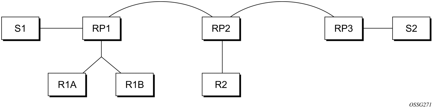
Figure 1 shows a scenario where all routers are connected, and where R1A, R1B, and R2 are receivers for a group, and S1 and S2 send to that group. Assume RP1, RP2, and RP3 are all assigned the same IP address that is used as the anycast-RP address (for example, the IP address is RPA).
Figure 1: Anycast RP for PIM-SM Implementation Example
| Note: The address used for the RP address in the domain (the anycast-RP address) must be different from the addresses used by the anycast-RP routers to communicate with each other. |
The following procedure is used when S1 starts sourcing traffic.
- S1 sends a multicast packet.
- The DR directly attached to S1 forms a PIM register message to send to the anycast-RP address (RPA). The unicast routing system delivers the PIM register message to the nearest RP, in this case RP1.
- RP1 receives the PIM register message, de-encapsulates it, and sends the packet down the shared tree to get the packet to receivers R1A and R1B.
- RP1 is configured with RP2 and RP3’s IP address. Because the register message did not come from one of the RPs in the anycast-RP set, RP1 assumes the packet came from a DR. If the register message is not addressed to the anycast-RP address, an error has occurred and it should be rate-limited logged.
- RP1 sends a copy of the register message from S1’s DR to both RP2 and RP3. RP1 uses its own IP address as the source address for the PIM register message.
- RP1 may join back to the source tree by triggering a (S1,G) Join message toward S1; however, RP1 must create the (S1,G) state.
- RP2 receives the register message from RP1, de-encapsulates it, and also sends the packet down the shared tree to get the packet to receiver R2.
- RP2 sends a register-stop message back to the RP1. RP2 may wait to send the register-stop message if it decides to join the source tree. RP2 should wait until it has received data from the source on the source tree before sending the register-stop message. If RP2 decides to wait, the register-stop message will be sent when the next register is received. If RP2 decides not to wait, the register-stop message is sent now.
- RP2 may join back to the source tree by triggering a (S1,G) Join message toward S1; however, RP2 must create the (S1,G) state.
- RP3 receives the register message from RP1 and de-encapsulates it, but, since there are no receivers joined for the group, it can discard the packet.
- RP3 sends a register-stop message back to RP1.
- RP3 creates a (S1,G) state so that when a receiver joins after S1 starts sending, RP3 can join quickly to the source tree for S1.
- RP1 processes the register-stop message from RP2 and RP3. RP1 may cache on a per-RP/per-(S,G) basis the receipt of register-stop messages from the RPs in the anycast-RP set. This option is performed to increase the reliability of register message delivery to each RP. When this option is used, subsequent register messages received by RP1 are sent only to the RPs in the anycast-RP set that have not previously sent register-stop messages for the (S,G) entry.
- RP1 sends a register-stop message back to the DR the next time a register message is received from the DR and, if all RPs in the anycast-RP set have returned register-stop messages for a particular (S,G) route when RP1 caches on a per-RP/per-(S,G) basis the receipt of register-stop messages from the RPs in the anycast-RP set.
The procedure for S2 sending follows the same preceding steps, but it is RP3 that sends a copy of the register originated by S2’s DR to RP1 and RP2. This example shows how sources anywhere in the domain, associated with different RPs, can reach all receivers, also associated with different RPs, in the same domain.
2.2.2.6. Distributing PIM Joins over Multiple ECMP Paths
The per bandwidth/round robin method is commonly used in multicast load balancing. However, the interface in an ECMP set can also be used for a channel to be predictable without any knowledge of the other channels using the ECMP set.
The mc-ecmp-hashing-enabled command enables PIM joins to be distributed over multiple ECMP paths based on a hash of S and G. When a link in the ECMP set is removed, the multicast streams using the link are redistributed over the remaining ECMP links using the same hash algorithm. When a link is added to the ECMP set, new joins may be allocated to the new link based on the hash algorithm, but existing multicast streams using the other ECMP links stay on those links until they are pruned.
The default is no mc-ecmp-hashing-enabled, which means that the use of multiple ECMP paths is controlled by the existing implementation and CLI commands, that is, mc-ecmp-balance.
The mc-ecmp-hashing-enabled command and the mc-ecmp-balance command are mutually exclusive in the same context.
The following procedure is used to achieve distribution of streams across the ECMP links.
- For a specific S, G get all possible nHops.
- Sort these nHops based on nHop addresses.
- xor S and G addresses.
- Hash the xor address over a number of PIM next hops.
- Use the hash value obtained in step 4, and get that element, in the sorted list obtained in step 2, as the preferred nHop.
- If this element is not available or it is not a PIM nHop (PIM neighbor), the next available next hop is chosen.
The following is a sample PIM status indicating ECMP hashing is disabled.
The following is a sample distribution of PIM joins over multiple ECMP paths.
2.2.3. Multicast Debugging Tools
This section describes multicast debugging tools for the 7210 SAS.
The debugging tools for multicast consist of two elements: mtrace and mrinfo.
2.2.3.1. Mtrace
Assessing problems in the distribution of IP multicast traffic can be difficult. The mtrace feature uses a tracing feature implemented in multicast routers that is accessed via an extension to the IGMP protocol. The mtrace feature is used to print the path from the source to a receiver; it does this by passing a trace query hop-by-hop along the reverse path from the receiver to the source. At each hop, information such as the hop address, routing error conditions, and packet statistics are gathered and returned to the requester.
Data added by each hop includes:
- query arrival time
- incoming interface
- outgoing interface
- previous hop router address
- input packet count
- output packet count
- total packets for this source/group
- Routing protocol
- TTL threshold
- Fowarding/error code
The information enables the network administrator to determine the following:
- Where multicast flows stop
- The flow of the multicast stream
When the trace response packet reaches the first-hop router (the router that is directly connected to the source’s network interface), that router sends the completed response to the response destination (receiver) address specified in the trace query.
If a multicast router along the path does not implement the traceroute feature or if there is an outage, no response is returned. To solve this problem, the trace query includes a maximum hop count field to limit the number of hops traced before the response is returned. This allows a partial path to be traced.
The reports inserted by each router contain not only the address of the hop, but also the TTL required to forward, flags to indicate routing errors, and counts of the total number of packets on the incoming and outgoing interfaces and those forwarded for the specified group. Examining the differences in these counts for two separate traces and comparing the output packet counts from one hop with the input packet counts of the next hop allows the calculation of packet rate and packet loss statistics for each hop to isolate congestion problems.
2.2.3.1.1. Finding the Last Hop Router
The trace query must be sent to the multicast router, which is the last hop on the path from the source to the receiver. If the receiver is on the local subnet (as determined using the subnet mask), the default method is to multicast the trace query to all-routers.mcast.net (224.0.0.2) with a TTL of 1. Otherwise, the trace query is sent to the group address because the last-hop router will be a member of that group if the receiver is. Therefore, it is necessary to specify a group that the intended receiver has joined. This multicast is sent with a default TTL of 64, which may not be sufficient for all cases.
When tracing from a multihomed host or router, the default receiver address may not be the desired interface for the path from the source. In such cases, the desired interface should be specified explicitly as the receiver.
2.2.3.1.2. Directing the Response
Unless the number of hops to trace is explicitly set with the hop option, mtrace first attempts to trace the full reverse path by default. If there is no response within a 3 second timeout interval, a "*" is displayed and the probing switches to hop-by-hop mode. Trace queries are issued starting with a maximum hop count of one and increasing by one until the full path is traced or no response is received. At each hop, multiple probes are sent. The first attempt is made with the unicast address of the host running mtrace as the destination for the response. Since the unicast route may be blocked, the remainder of attempts request that the response be multicast to mtrace.mcast.net (224.0.1.32) with the TTL set to 32 more than what is needed to pass the thresholds seen so far along the path to the receiver. For the final attempts, the TTL is increased by another 32.
Alternatively, the TTL may be set explicitly with the TTL option.
The output of mtrace is a short listing of the hops in the order they are queried, that is, in the reverse of the order from the source to the receiver. For each hop, a line is displayed showing:
- the hop number (counted negatively to indicate that this is the reverse path)
- the multicast routing protocol
- the threshold required to forward data (to the previous hop in the listing as indicated by the up-arrow character)
- the cumulative delay for the query to reach that hop (valid only if the clocks are synchronized)
The response ends with a line showing the round-trip time, which measures the interval from the time the query is issued until the response is received, both derived from the local system clock.
Mtrace packets use special IGMP packets with IGMP type codes of 0x1E and 0x1F.
2.2.3.2. Mrinfo
The mrinfo feature is a simple mechanism to display configuration information from the target multicast router. The type of information displayed includes the multicast capabilities of the router, code version, metrics, TTL thresholds, protocols, and status. This information can be used by network operators to verify if bidirectional adjacencies exist. When the specified multicast router responds, the configuration is displayed.
2.2.4. Configuration Guidelines for 7210 SAS
The following are the configuration guidelines for the 7210 SAS.
- 7210 SAS platforms can be used as RPs.
- Static RP configuration using PIM BSR messages is supported.
- It is possible to configure the 7210 SAS as a First Hop Multicast router (FHR) from the source in a PIM-SM network.
- 7210 SAS devices provide an option to either switch over to the SPT or continue to use the shared tree. However, the traffic rate threshold cannot be configured to trigger the switch over.
- RFP checks are performed using the unicast routing table. Multicast BGP and multicast routing table are not supported.