8. Virtual Private Network Service on 7210 SAS-K 2F6C4T and 7210 SAS-K 3SFP+ 8C
This chapter provides information about the Virtual Private Routed Network (VPRN) service and implementation notes on the 7210 SAS-K 2F6C4T and 7210 SAS-K 3SFP+ 8C.
8.1. VPRN Service Overview
RFC2547bis is an extension to the original RFC 2547, which details a method of distributing routing information and forwarding data to provide a Layer 3 Virtual Private Network (VPN) service to end customers.
Each Virtual Private Routed Network (VPRN) consists of a set of customer sites connected to one or more PE routers. Each associated PE router maintains a separate IP forwarding table for each VPRN. Additionally, the PE routers exchange the routing information configured or learned from all customer sites via MP-BGP peering. Each route exchanged via the MP-BGP protocol includes a Route Distinguisher (RD), which identifies the VPRN association.
The service provider uses BGP to exchange the routes of a VPN among the PE routers that are attached to that VPN. This is done in a way which ensures that routes from different VPNs remain distinct and separate, even if two VPNs have an overlapping address space. The PE routers distribute routes from other CE routers in that VPN to the CE routers in a VPN. Since the CE routers do not peer with each other there is no overlay visible to the VPN's routing algorithm.
When BGP distributes a VPN route, it also distributes an MPLS label for that route. The label distributed with a VPN route depends on the configured label-mode of the VPRN that is originating the route. On 7210 SAS routers, only one method of label allocation mode is supported: label per VRF. That is, when 7210 allocates a label for a VPN route, it allocates a single label for all the VPN routes belonging to a single VRF. This does not restrict the label distribution method on the remote PE. The label distribution method configured on the remote PE must consider the scale of the PEs participating in the VPRN service.
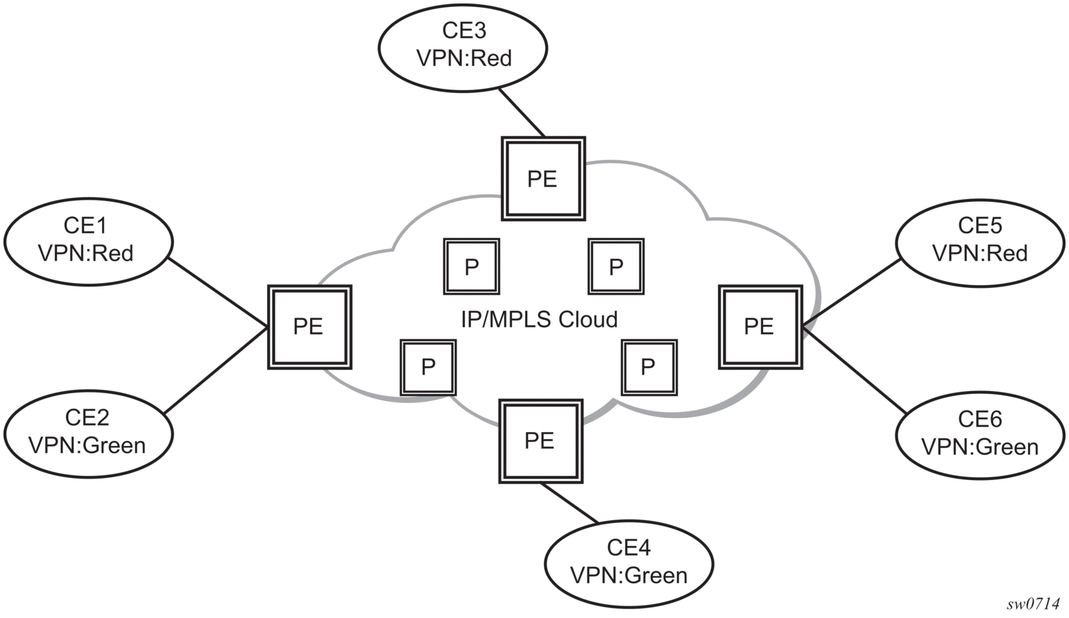
Before a customer data packet travels across the service provider's backbone, it is encapsulated with the MPLS label that corresponds, in the customer's VPN, to the route which best matches the packet's destination address. The MPLS packet is further encapsulated with either another MPLS label header, so that it gets tunneled across the backbone to the correct PE router. Each route exchanged by the MP-BGP protocol includes a route distinguisher (RD), which identifies the VPRN association. Therefore, the backbone core routers do not need to know the VPN routes. Figure 80 shows a VPRN network diagram example.
Figure 80: Virtual Private Routed Network
8.1.1. Routing Prerequisites
RFC2547bis requires the following features:
- Multi-protocol extensions
- Extended BGP community support
- BGP capability negotiation
- Parameters defined in RFC 2918
Tunneling protocol options are as follows:
- Label Distribution Protocol (LDP)
- MPLS RSVP-TE tunnels
8.1.2. BGP Support
BGP is used with BGP extensions to distribute VPRN routing information across the service provider's network. BGP was initially designed to distribute IPv4 routing information. Therefore, multi-protocol extensions and the use of a VPN-IPv4 address were created to extend BGP's ability to carry overlapping routing information. A VPN-IPv4 address is a 12-byte value consisting of the 8-byte route distinguisher (RD) and the 4-byte IPv4 IP address prefix. The RD must be unique within the scope of the VPRN. This allows the IP address prefixes within different VRFs to overlap.
The 7210 SAS-K 2F6C4T and 7210 SAS-K 2F6C4T provide 6PE support in the base routing instance with BGP 3017 labeled routes to interconnect IPv6 networks over an IP/MPLS infrastructure.
8.1.3. Route Distinguisher
Figure 81 shows the route distinguisher (RD), an 8-byte value consisting of 2 major fields, the Type field and value field. The type field determines how the value field should be interpreted. The 7210 SAS implementation supports the three (3) type values as defined in the internet draft.
Figure 81: Route Distinguisher

The three Type values are:
- Type 0: Value Field - Administrator subfield (2 bytes)Assigned number subfield (4 bytes)The administrator field must contain an ASN (using private ASNs is discouraged). The Assigned field contains a number assigned by the service provider.
- Type 1: Value Field - Administrator subfield (4 bytes)Assigned number subfield (2 bytes)The administrator field must contain an IP address (using private IP address space is discouraged). The Assigned field contains a number assigned by the service provider.
- Type 2: Value Field - Administrator subfield (4 bytes)Assigned number subfield (2 bytes)The administrator field must contain a 4-byte ASN (using private ASNs is discouraged). The Assigned field contains a number assigned by the service provider.
8.1.4. Route Reflector
Per RFC2547bis the use of Route Reflectors is supported in the service provider core. Multiple sets of route reflectors can be used for different types of BGP routes, including VPN-IPv4, etc. The 7210 SAS-K 2F6C4T or 7210 SAS-K 3SFP+ 8C can only be configured a route reflector client. It cannot be used as a route reflector “server” in the network.
8.1.5. CE to PE Route Exchange
Routing information between the Customer Edge (CE) and Provider Edge (PE) can be exchanged by the following methods:
- Static routes (IPv4 and IPv6)
- E-BGP (IPv4 and IPv6)
- OSPFv2 (IPv4)
Each protocol provides controls to limit the number of routes learned from each CE router.
8.1.5.1. Route Redistribution
Routing information learned from the CE-to-PE routing protocols and configured static routes should be injected in the associated local VPN routing/forwarding (VRF). In the case of dynamic routing protocols, there may be protocol specific route policies that modify or reject certain routes before they are injected into the local VRF.
Route redistribution from the local VRF to CE-to-PE routing protocols is to be controlled via the route policies in each routing protocol instance, in the same manner that is used by the base router instance.
The advertisement or redistribution of routing information from the local VRF to or from the MPBGP instance is specified per VRF and is controlled by VRF route target associations or by VRF route policies.
VPN-IP routes imported into a VPRN, have the protocol type bgp-vpn to denote that it is an VPRN route. This can be used within the route policy match criteria.
8.1.5.2. CPE Connectivity Check
Static routes are used within many IES and VPRN services. Unlike dynamic routing protocols, there is no way to change the state of routes based on availability information for the associated CPE. CPE connectivity check adds flexibility so that unavailable destinations will be removed from the VPRN routing tables dynamically and minimize wasted bandwidth.
Figure 82 shows static route connection information. Figure 83 shows multiple hop information.
Figure 82: Directly connected to IP target
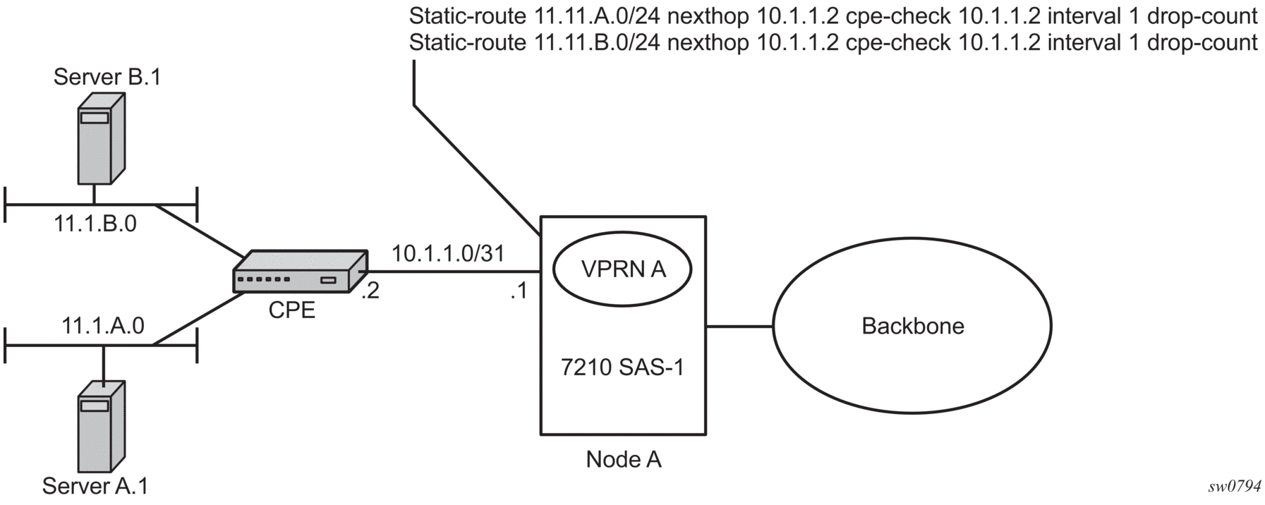
Figure 83: Multiple Hops to IP target
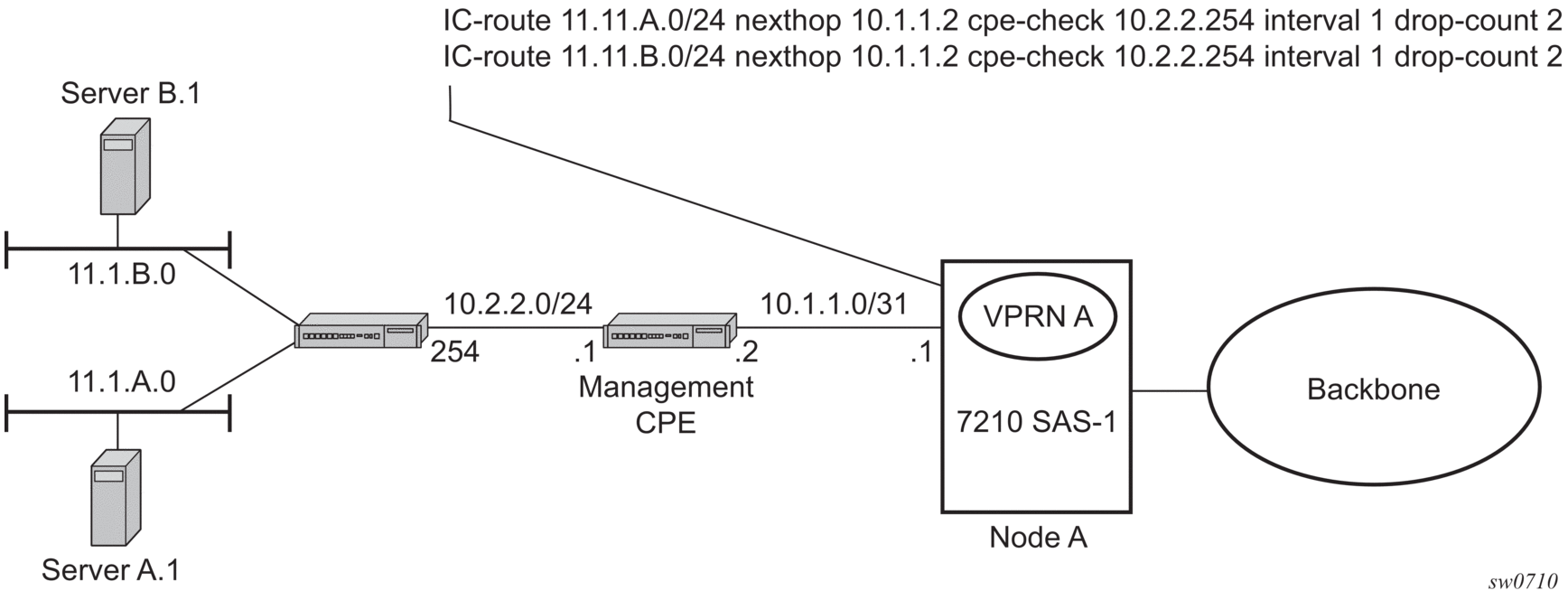
The availability of the far-end static route is monitored through periodic polling. The polling period is configured. If the poll fails a specified number of sequential polls, the static route is marked as inactive.
Either ICMP ping or unicast ARP mechanism can be used to test the connectivity. ICMP ping is preferred.
If the connectivity check fails and the static route is deactivated, the 7210 SAS router will continue to send polls and reactivate any routes that are restored.
8.2. VPRN Features
This section describes various VPRN features and any special capabilities or considerations as they relate to VPRN services.
8.2.1. IP Interfaces
VPRN customer IP interfaces can be configured with most of the same options found on the core IP interfaces.
The advanced configuration options supported are:
- ICMP and ICMP6 options
- VRRP — for VPRN services with more than one IPv4 interface
8.2.2. SAPs
The following sections describe SAP functionality on VPRN services.
8.2.2.1. IPv6 Support for VPRN IP Interfaces (6VPE) in Network Mode
VPRN IPv6 (6VPE) access interfaces can be configured to provide IPv6 VPN connectivity to customers.
IPv4 and IPv6 route table lookup entries are shared. Before adding routes for IPv6 destinations, route entries in the routed lookup table need to be allocated for IPv6 addresses. This is done using the CLI command config> system> resource-profile> router> maxipv6- routes. This command allocates route entries for /64 IPv6 prefix route lookups. The system does not allocate any IPv6 route entries by default; the user needs to allocate resources before using IPv6. For the command to take effect the node must be rebooted after making the change.
A separate route table (or a block in the route table) is used for IPv6 /128-bit prefix route lookup. A limited amount of IPv6 /128 prefixes route lookup entries is supported. The software enables lookups in this table by default (that is, no user configuration is required to enable Ipv6 /128-bit route lookup). A limited amount of IPv6 /128 prefixes route lookup entries is supported.
The number of IP subnets can be configured using the command configure> system>resource-profile>router>max-ip-subnets. Default are assigned to this parameter. Users can increase the number of subnets if they plan to more IPv6 addresses per IPv6 interface.
8.2.2.2. Encapsulations
The following SAP encapsulations are supported on the 7210 SAS VPRN service:
- Ethernet null
- Ethernet dot1q
- QinQ
- LAG
8.2.2.3. QoS Policies for 7210 SAS-K 2F6C4T and 7210 SAS-K 3SFP+ 8C
When applied to a VPRN SAP, service ingress and service egress QoS policies create the unicast and multicast queues defined in the policy (as multicast is not supported in VPRN service). Note that both Layer 2 (dot1p only) or Layer-3 criteria can be used in the QoS policies for traffic classification in an VPRN.
8.2.2.4. Filter Policies
Ingress and egress IPv4 and IPv6 filter policies can be applied to VPRN SAPs.
8.2.2.5. CPU QoS for VPRN interfaces
Traffic bound to the CPU that is received on VPRN access interfaces is policed/rate-limited and is added to the CPU queues. The software allocates a policer per IP application, or a set of IP applications, for rate-limiting CPU bound IP traffic from all VPRN SAPs. The policer CIR/PIR values are set to appropriate values based on feature scaling. CIR/PIR values are not user configurable. The policers are shared by the IP application/set of IP applications traffic received on all access SAPs across all services. Queues for CPU bound IP traffic from all VPRN SAPs are software allocated. The queues are either shared by a set of IP applications or allocated to a single IP application across all services and routing instances. The queues are shaped to an appropriate rate based on feature scaling. The shaper rate is not user configurable. The queues and shaper rate are shared by traffic of the IP application/set of IP applications received on all access SAPs. The queue instances and policers used for traffic received on network port IP interfaces are different for traffic received from access port IP interfaces. Also, the network CPU queues are given higher priority than the access CPU queues. This provides better security and mitigates the risk of access traffic affecting the network side.
Note:
|
8.2.3. CE to PE Routing Protocols
The 7210 SAS VPRN supports the following PE to CE routing protocols:
- eBGP (IPv4 and IPv6)
- Static (IPv4 and IPv6)
- OSPFv2 (IPv4)
8.2.3.1. PE to PE Tunneling Mechanisms
The 7210 SAS supports multiple mechanisms to provide transport tunnels for the forwarding of traffic between PE routers within the 2547bis network. The 7210 SAS VPRN implementation supports the use of:
- RSVP-TE protocol to create tunnel LSP's between PE routers
- LDP protocol to create tunnel LSP's between PE routers
These transport tunnel mechanisms provide the flexibility of using dynamically created LSPs where the service tunnels are automatically bound (the “auto-bind” feature) and the ability to provide certain VPN services with their own transport tunnels by explicitly binding SDPs if desired. When the auto-bind is used, all services traverse the same LSPs and do not allow alternate tunneling mechanisms or the ability to craft sets of LSP's with bandwidth reservations for specific customers as is available with explicit SDPs for the service.
8.2.3.2. Per VRF Route Limiting
The 7210 SAS allows setting the maximum number of routes that can be accepted in the VRF for a VPRN service. There are options to specify a percentage threshold at which to generate an event that the VRF table is near full and an option to disable additional route learning when full or only generate an event.
8.2.4. Spoke-SDP termination
Spoke-SDP termination into a Layer 3 service is not supported on 7210 SAS platforms. On the 7210 SAS-K 2F6C4T, spoke-SDP termination is supported on a routed VPLS that is associated with a VPRN service. All commands supported in the config>service>vpls>spoke-sdp context are supported on a routed VPLS. See VPLS Spoke-SDP Commands for 7210 SAS-K 2F6C4T and 7210 SAS-K 3SFP+ 8C for information about the spoke-sdp command.
8.2.4.1. Using OSPF in IP-VPNs
| Note: OSPFv2 as PE-CE routing protocol is supported for IPv4 VPNs. OSPFv3 is not supported as a PE-CE routing protocol. |
Using OSPF as a CE to PE routing protocol allows OSPF that is currently running as the IGP routing protocol to migrate to an IP-VPN backbone without changing the IGP routing protocol, introducing BGP as the CE-PE or relying on static routes for the distribution of routes into the service providers IP-VPN. The following features are supported:
- Advertisement/redistribution of BGP-VPN routes as summary (type 3) LSAs flooded to CE neighbors of the VPRN OSPF instance. This occurs if the OSPF route type (in the OSPF route type BGP extended community attribute carried with the VPN route) is not external (or NSSA) and the locally configured domain-id matches the domain-id carried in the OSPF domain ID BGP extended community attribute carried with the VPN route.
- OSPF sham links. A sham link is a logical PE-to-PE unnumbered point-to-point interface that essentially rides over the PE-to-PE transport tunnel. A sham link can be associated with any area and can therefore appear as an intra-area link to CE routers attached to different PEs in the VPN.
8.2.5. Service Label Mode of a VPRN
The 7210 SAS allocates one unique (platform-wide) service label per VRF. All VPN-IP routes exported by the PE from a particular VPRN service with that configuration have the same service label. When the PE receives a terminating MPLS packet, the service label value determines the VRF to which the packet belongs. A lookup of the IP packet DA in the forwarding table of the selected VRF determines the next-hop interface.
8.2.5.1. Inter-AS VPRNs
Inter-AS IP-VPN services have been driven by the popularity of IP services and service provider expansion beyond the borders of a single Autonomous System (AS) or the requirement for IP VPN services to cross the AS boundaries of multiple providers. Three options for supporting inter-AS IP-VPNs are described in RFC 4364, BGP/MPLS IP Virtual Private Networks (VPNs).
| Note: The 7210 SAS-K 2F6C4T and 7210 SAS-K 3SFP+ 8C platforms support only option-A and option-C. They do not support option-B. It is described as follows only for the sake of completeness. |
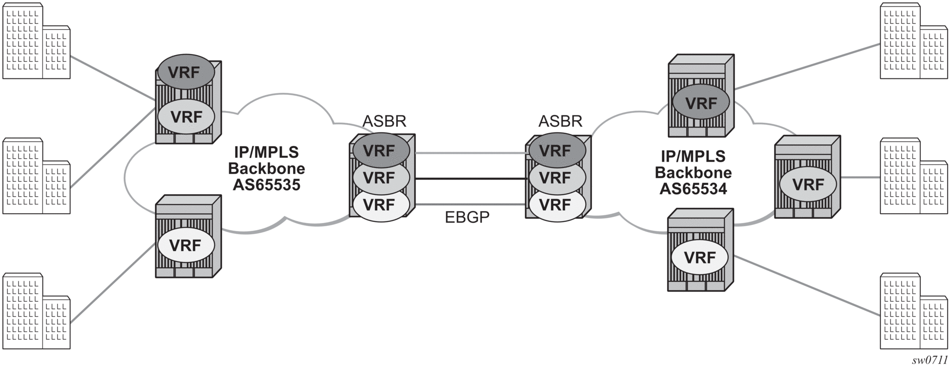
The first option, referred to as Option-A (Figure 84), is considered inherent in any implementation. This method uses a back-to-back connection between separate VPRN instances in each AS. Therefore, each VPRN instance views the inter-AS connection as an external interface to a remote VPRN customer site. The back-to-back VRF connections between the ASBR nodes require individual sub-interfaces, one per VRF.
Figure 84: Inter-AS Option-A: VRF-to-VRF Model
The second option, referred to as Option-B (Figure 85), relies heavily on the AS Boundary Routers (ASBRs) as the interface between the autonomous systems. This approach enhances the scalability of the eBGP VRF-to-VRF solution by eliminating the need for per-VPRN configuration on the ASBRs. However, it requires that the ASBRs provide a control plan and forwarding plane connection between the autonomous systems. The ASBRs are connected to the PE nodes in its local autonomous system using iBGP either directly or through route reflectors. This means the ASBRs receive all the VPRN information and will forward these VPRN updates, VPN-IPv4, to all its EBGP peers, ASBRs, using itself as the next-hop. It also changes the label associated with the route. This means the ASBRs must maintain an associate mapping of labels received and labels issued for those routes. The peer ASBRs will in turn forward those updates to all local IBGP peers,
Figure 85: Inter-AS Option-B
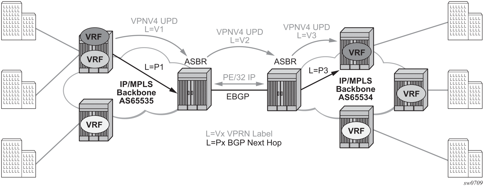
This form of inter-AS VPRNs does not require instances of the VPRN to be created on the ASBR, as in option-A, therefore there is less management overhead. This is also the most common form of Inter-AS VPRNs used between different service providers as all routes advertised between autonomous systems can be controlled by route policies on the ASBRs.
The third option, referred to as Option-C (Figure 86), allows for a higher scale of VPRNs across AS boundaries but also expands the trust model between ASNs. Therefore, this model is typically used within a single company that may have multiple ASNs for various reasons.
This model differs from Option-B, in that in Option-B all direct knowledge of the remote AS is contained and limited to the ASBR. Therefore, in option-B the ASBR performs all necessary mapping functions and the PE routers do not need perform any additional functions then in a non-Inter-AS VPRN.
Figure 86: Option C Example
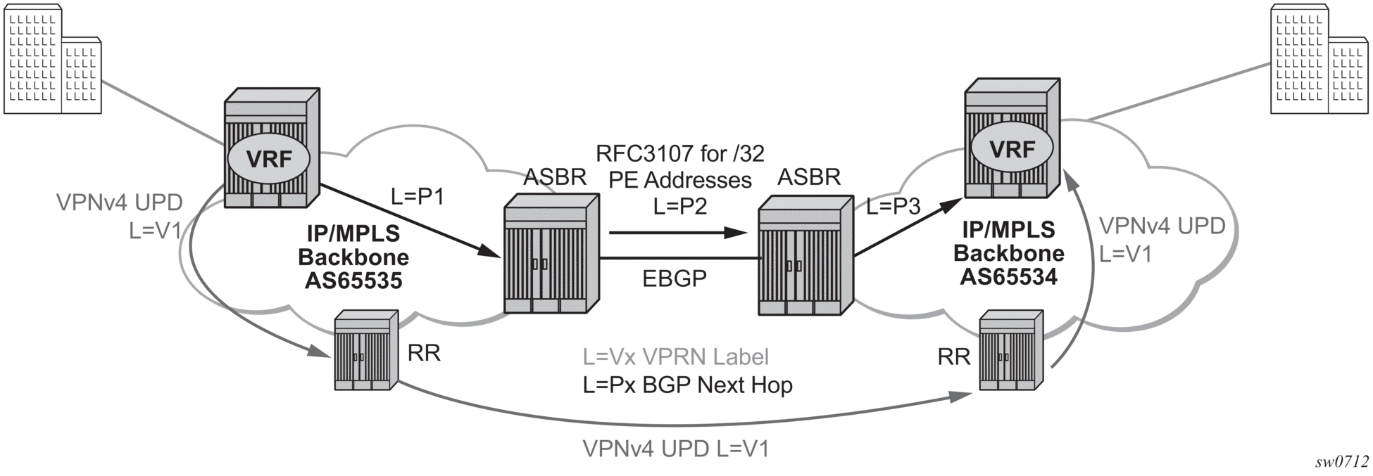
With Option-C, knowledge from the remote AS is distributed throughout the local AS. This distribution allows for higher scalability but also requires all PEs and ASBRs involved in the Inter-AS VPRNs to participate in the exchange of inter-AS routing information. In Option-C, the ASBRs distribute reachability information for remote PE's system IP addresses only. This is done between the ASBRs by exchanging MP-eBGP labeled routes, using RFC 3107, Carrying Label Information in BGP-4.
| Note: The 7210 SAS-K 2F6C4T and 7210 SAS-K 3SFP+ 8C do not play the role of option-C ASBR. |
Distribution of VPRN routing information is handled by either direct MP-BGP peering between PEs in the different ASNs or more likely by one or more route reflectors in ASN.
8.2.5.2. VRRP Support for VPRN IP Interfaces in Network Mode
Virtual Router Redundancy Protocol (VRRP) for IPv4 is defined in IETF RFC 3768, Virtual Router Redundancy Protocol. VRRP describes a method of implementing a redundant IP interface shared between two or more routers on a common LAN segment, allowing a group of routers to function as one virtual router. When this IP interface is specified as a default gateway on hosts directly attached to this LAN, the routers sharing the IP interface prevent a single point of failure by limiting access to this gateway address. For more information about the use of VRRP, refer to the 7210 SAS-D, Dxp, K 2F1C2T, K 2F6C4T, K 3SFP+ 8C Router Configuration Guide.
VRRP is supported for VRRP IPv4 interfaces. It is not supported for IPv6 interfaces in network or access-uplink mode.
| Note: Only one VRRP instance for each IP interface is supported on the 7210 SAS-K 2F6C4T and 7210 SAS-K 3SFP+ 8C. |
8.3. Configuring a VPRN Service with CLI
This section provides information to configure Virtual Private Routed Network (VPRN) services using the command line interface.
8.3.1. Basic Configuration
The following fields require specific input (there are no defaults) to configure a basic VPRN service:
- Customer ID (refer to Configuring Customer Accounts
- Specify interface parameters
The following is a sample configuration output of a VPRN service.
8.3.2. Common Configuration Tasks
This section provides a brief overview of the tasks that must be performed to configure a VPRN service and provides the CLI commands.
- Associate a VPRN service with a customer ID.
- Define an autonomous system (optional).
- Define a route distinguisher (mandatory).
- Define VRF route-target associations or VRF import/export policies.
- Create an interface.
- Define SAP parameters on the interface.
- Select nodes and ports.
- Optional - select QoS policies other than the default (configured in config>qos context).
- Optional - select filter policies (configured in config>filter context).
- Optional - select accounting policy (configured in config>log context).
- Define BGP parameters (optional).
- BGP must be enabled in the config>router>bgp context.
- Enable the service.
8.3.3. Configuring VPRN Components
8.3.3.1. Creating a VPRN Service
Use the following syntax to create a VRPN service. A route distinguisher must be defined for VPRN to be operationally active.
The following is a sample VPRN service configuration output.
8.3.3.2. Configuring Global VPRN Parameters
Refer to VPRN Services Command Reference on page 681 for CLI syntax to configure VPRN parameters.
The following is a sample VPRN service with configured parameters.
8.3.3.3. Configuring Router Interfaces
Refer to the 7210 SAS OS Router Configuration Guide for command descriptions and syntax information to configure router interfaces.
The following is a sample router interface configuration output.
8.3.3.4. Configuring VPRN Protocols - BGP
The ASN and router ID configured in the VPRN context only applies to that particular service.
The minimal parameters that should be configured for a VPRN BGP instance are:
- Specify an autonomous system number for the router. See Configuring Global VPRN Parameters.
- Specify a router ID - Note that if a new or different router ID value is entered in the BGP context, then the new values takes precedence and overwrites the VPRN-level router ID.
See Configuring Global VPRN Parameters.
- Specify a VPRN BGP peer group.
- Specify a VPRN BGP neighbor with which to peer.
- Specify a VPRN BGP peer-AS that is associated with the preceding peer.
VPRN BGP is administratively enabled upon creation. Minimally, to enable VPRN BGP in a VPRN instance, you must associate an autonomous system number and router ID for the VPRN service, create a peer group, neighbor, and associate a peer ASN. There are no default VPRN BGP groups or neighbors. Each VPRN BGP group and neighbor must be explicitly configured.
All parameters configured for VPRN BGP are applied to the group and are inherited by each peer, but a group parameter can be overridden on a specific basis. VPRN BGP command hierarchy consists of three levels:
- The global level
- The group level
- The neighbor level
For example:
Note that the local-address must be explicitly configured if two systems have multiple BGP peer sessions between them for the session to be established.
For more information about the BGP protocol, refer to the 7210 SAS OS Router configuration Guide.
8.3.3.5. Configuring VPRN BGP Group and Neighbor Parameters
A group is a collection of related VPRN BGP peers. The group name should be a descriptive name for the group. Follow your group, name, and ID naming conventions for consistency and to help when troubleshooting faults.
All parameters configured for a peer group are applied to the group and are inherited by each peer (neighbor), but a group parameter can be overridden on a specific neighbor-level basis.
After a group name is created and options are configured, neighbors can be added within the same autonomous system to create IBGP connections and/or neighbors in different autonomous systems to create EBGP peers. All parameters configured for the peer group level are applied to each neighbor, but a group parameter can be overridden on a specific neighbor basis.
Use the CLI syntax to configure VPRN BGP parameters (BGP Configuration Commands on page 691).
The following is a sample VPRN BGP configuration output.
8.3.3.6. Configuring a VPRN Interface
Interface names associate an IP address to the interface, and then associate the IP interface with a physical port. The logical interface can associate attributes like an IP address, port, Link Aggregation Group (LAG) or the system.
There are no default interfaces.
Note that you can configure a VPRN interface as a loop-back interface by issuing the loop-back command instead of the sap sap-id command. The loop-back flag cannot be set on an interface where a SAP is already defined and a SAP cannot be defined on a loop-back interface.
The following is a sample VPRN interface configuration output.
8.3.3.7. Configuring a VPRN Interface SAP
A SAP is a combination of a port and encapsulation parameters which identifies the service access point on the interface and within the 7210 SAS. Each SAP must be unique within a router. A SAP cannot be defined if the interface loop-back command is enabled.
When configuring VPRN interface SAP parameters, a default QoS policy is applied to each ingress and egress SAP. Additional QoS policies and scheduler policies must be configured in the config>qos context. Filter policies are configured in the config>filter context and must be explicitly applied to a SAP. There are no default filter policies.
The following is a sample VPRN interface SAP configuration output.
8.3.3.8. Configuring VRRP
Configuring VRRP parameters on a VPRN interface is optional. VRRP can be configured in either owner or non-owner mode. The owner is the VRRP router whose virtual router IP address is the same as the real interface IP address. This is the router that responds to packets addressed to one of the IP addresses for ICMP pings, TCP connections, and related addresses. All other virtual router instances participating in this message domain should have the same VRID configured and cannot be configured as an owner.
The following is a sample VRRP interface VRRP owner configuration output.
8.3.3.9. Configuring IPv6 Parameters for VPRN BGP
Use the following syntax to configure IPv6 parameters for VPRN BGP.
8.3.3.10. Configuring VPRN IPv6 Neighbor Discovery Parameters
Use the following syntax to configure IPv6 neighbor discovery parameters for a VPRN service.
8.3.3.11. Configuring OSPF for VPRN
Use the following syntax to configure OSPF in the VPRN context.
Refer to OSPF Configuration Commands for the CLI syntax to configure VPRN OSPF parameters.
The following is a sample VPRN OSPF configuration output.
8.3.4. Service Management Tasks
This section describes the service management tasks.
8.3.4.1. Modifying VPRN Service Parameters
Use the syntax to modify VPRN parameters (VPRN Services Command Reference for 7210 SAS-K 2F6C4T and 7210 SAS-K 3SFP+ 8C).
The following is a sample VPRN service creation output.
8.3.4.2. Deleting a VPRN Service
An VPRN service cannot be deleted until SAPs and interfaces are shut down and deleted. If protocols and/or a spoke-SDP are defined, they must be shut down and removed from the configuration as well.
Use the following syntax to delete a VPRN service.
8.3.4.3. Disabling a VPRN Service
Use the following syntax to shut down a VPRN service without deleting any service parameters.
8.3.4.4. Re-enabling a VPRN Service
Use the following syntax to re-enable a VPRN service that was shut down.