3.9. Configuring a VLL Service with CLI
This section provides information to configure Virtual Leased Line (VLL) services using the command line interface.
3.9.1. Basic Configurations
3.9.2. Common Configuration Tasks
This section provides a brief overview of the tasks that must be performed to configure the VLL services and provides the CLI commands.
- Associate the service with a customer ID
- Define SAP parameters
- Optional - select ingress QoS policies (configured in the config>qos context).
- Optional - select accounting policy (configured in the config>log context).
- Define spoke-SDP parameters
- Enable the service
3.9.3. Configuring VLL Components
This section provides VLL configuration examples for the VLL services.
3.9.3.1. Creating an Epipe Service
Use the following syntax to create an Epipe service.
The following is a sample Epipe configuration output.
3.9.3.1.1. Configuring Epipe SAP Parameters
A default QoS policy is applied to each ingress SAP. Additional QoS policies can be configured in the config>qos context. Filter policies are configured in the config>filter context and explicitly applied to a SAP. There are no default filter policies.
3.9.3.1.1.1. Local Epipe SAPs
To configure a basic local Epipe service, enter the sap sap-id command twice with different port IDs in the same service configuration.
By default, QoS policy ID 1 is applied to ingress service SAPS. Existing filter policies or other existing QoS policies can be associated with service SAPs on ingress and egress ports.
Ingress and Egress SAP parameters can be applied to local and distributed Epipe service SAPs.
This example displays the SAP configurations for local Epipe service 500 on SAP 1/1/2 and SAP 1/1/3 on ALA-1.
3.9.4. Using Spoke-SDP Control Words
The control word command provides the option to add a control word as part of the packet encapsulation for PW types for which the control word is optional. On 7210 an option is provided to enable it for Ethernet PW (Epipe). The control word might be needed because when ECMP is enabled on the network, packets of a specific PW may be spread over multiple ECMP paths if the hashing router mistakes the PW packet payload for an IPv4 or IPv6 packet. This occurs when the first nibble following the service label corresponds to a value of 4 or 6.
The control word negotiation procedures described in Section 6.2 of RFC 4447 are not supported and therefore the service will only come up if the same C bit value is signaled in both directions. If a spoke-SDP is configured to use the control word but the node receives a label mapping message with a C-bit clear, the node releases the label with an “Illegal C-bit” status code per Section 6.1 of RFC 4447. As soon as the user enables control of the remote peer, the remote peer withdraws its original label and sends a label mapping with the C-bit set to 1 and the VLL service is up in both nodes.
When the control word is enabled, VCCV packets also include the VCCV control word. In that case, the VCCV CC type 1 (OAM CW) is signaled in the VCCV parameter in the FEC. If the control word is disabled on the spoke-SDP, then the Router Alert label is used. In that case, VCCV CC type 2 is signaled. Note that for a multi-segment PW (MS-PW), the CC type 1 is the only supported and therefore the control word must be enabled on the spoke-SDP to be able to use VCCV ping and VCCV trace.
The following is a sample spoke-SDP control word configuration output.
3.9.5. Pseudowire Configuration Notes
The vc-switching parameter must be specified at the time the VLL service is created. Note that when the vc-switching parameter is specified, you are configuring an S-PE. This is a pseudowire switching point (switching from one pseudowire to another). Therefore, you cannot add a SAP to the configuration.
The following example show the configuration when a SAP is added to a pseudowire. The CLI generates an error response if you attempt to create a SAP. VC switching is only needed on the pseudowire at the S-PE.
Use the following syntax to create pseudowire switching VLL services.
The following shows the command usage to configure VLL pseudowire switching services.
S-PE1: Note that specifying the vc-switching parameter enables a VC cross-connect so the service manager does not signal the VC label mapping immediately but will put this into passive mode.
The following is a sample configuration output.
S-PE2: Note that specifying the vc-switching parameter enables a VC cross-connect so the service manager does not signal the VC label mapping immediately but will put this into passive mode.
The following is a sample configuration output.
3.9.6. Configuring VLL Resilience
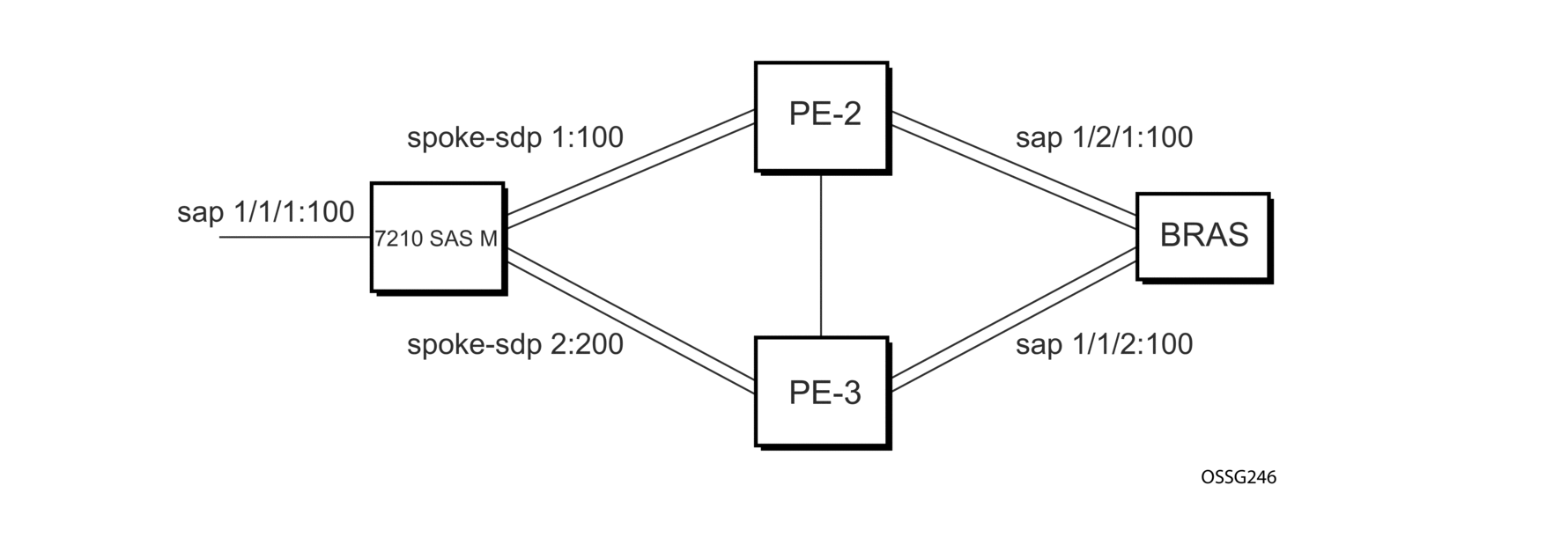
Figure 32 shows an example to create VLL resilience. Note that the zero revert-time value means that the VLL path will be switched back to the primary immediately after it comes back up.
Figure 32: VLL Resilience

PE1:
The following is a sample configuration output on PE1.
3.9.7. Configuring VLL Resilience for a Switched Pseudowire Path
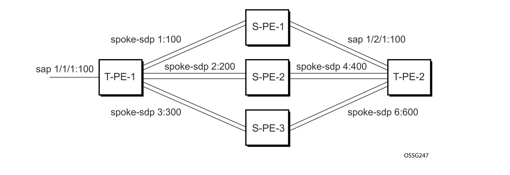
Figure 33 shows an example to create VLL resilience with pseudowire switching.
Figure 33: VLL Resilience with Pseudowire Switching

T-PE1
The following is a sample configuration output on TPE1.
T-PE2
The following is a sample configuration output on TPE2.
S-PE1
The following is a sample configuration output on S-PE1.
3.9.8. Service Management Tasks
This section describes the Epipe service management tasks.
3.9.8.1. Modifying Epipe Service Parameters
The following displays an example of adding an accounting policy to an existing SAP:
Example: config>service# epipe 2 config>service>epipe# sap config>service>epipe>sap# accounting-policy 14 config>service>epipe>sap# exit
The following is a sample SAP configuration output.
3.9.8.2. Disabling an Epipe Service
Use the following syntax to shut down an Epipe service without deleting the service parameters.
Example:config>service# epipe 2 config>service>epipe# shutdown config>service>epipe# exit
3.9.8.3. Re-Enabling an Epipe Service
Use the following syntax to re-enable an Epipe service that was shut down.
Example: config>service# epipe 2 config>service>epipe# no shutdown config>service>epipe# exit
3.9.8.4. Deleting an Epipe Service
Perform the following steps before deleting an Epipe service:
- Shut down the SAP.
- Delete the SAP.
- Shut down the service.
Use the following syntax to delete an Epipe service.
Example: config>service# epipe 2 config>service>epipe# sap config>service>epipe>sap# shutdown config>service>epipe>sap# exit config>service>epipe# no sap config>service>epipe# epipe 2 config>service>epipe# shutdown config>service>epipe# exit config>service# no epipe 2