2. 7210 SAS Interfaces
This chapter provides information about configuring chassis slots, cards, and ports.
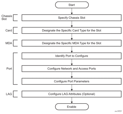
2.1. Configuration Overview
| Note: This document uses the term preprovisioning in the context of preparing or preconfiguring entities such as chassis slots, media dependent adapters (MDAs), ports, and interfaces, before initialization. These entities can be installed but not enabled. When the entity is in a no shutdown state (administratively enabled), the entity is considered to be provisioned. |
The 7210 SAS-D, 7210 SAS-Dxp, 7210 SAS-K 2F1C2T, 7210 SAS-K 2F6C4T, and 7210 SAS-K 3SFP+ 8C and the variants are platforms with a fixed port configuration, and no expansion slots. The 7210 SAS software inherits the concept of CPM, IOM and MDA from the 7750 SR to represent the hardware logically. These components are fixed and are not removable. The software creates two logical cards to represent the CPM and IOM and these are preprovisioned on boot-up. The IOM card is modeled with a single MDA, a logical entity to represent the fixed ports on the system. This MDA is auto-provisioned on boot-up and the user does not need to provision it. Ports and interfaces can also be preprovisioned.
2.1.1. Chassis Slots and Cards
- The 7210 SAS-D supports the following ports:
- 6 × 10/100/1000 SFP ports
- 4 × 10/100/1000 Base-T ports
- 1 management console port
- The 7210 SAS-Dxp supports the following ports:
- 2 × 1GE/10GE SFP+ ports
- 6 × 10/100/1000 Base-T ports
- 4 × 100/1000 SFP ports
- 1 management console port
- The 7210 SAS-K 2F1C2T supports the following ports:
- 2 × 10/100/1000 Base-T fixed copper ports
- 1 management console port
- The 7210 SAS-K 2F6C4T supports the following ports:
- 2 × 100/1000 SFP ports
- 4 × 10/100/1000 Base-T fixed copper ports
- 6 Combo ports (100/1000 SFP or 10/100/1000 Base-T)
- 1 management console port
- The 7210 SAS-K 3SFP+ 8C ports supports the following ports:
- 3 × 10GE SFP+ ports
- 8 Combo ports (100/1000 SFP or 10/100/1000 Base-T)
- 1 management console port
The 7210 SAS-D, 7210 SAS-Dxp, 7210 SAS-K 2F1C2T, 7210 SAS-K 2F6C4T, and 7210 SAS-K 3SFP+ 8C have a set of fixed ports. The software preprovisions the cards on bootup.
The show card command lists the cards auto-provisioned on 7210 SAS platforms.
The following show card sample output lists the cards auto-provisioned on the 7210 SAS-D:
The following show card sample output lists the cards auto-provisioned on the 7210 SAS-Dxp:
The following show card sample output lists the cards auto-provisioned on the 7210 SAS-K 2F1C2T:
The following show card sample output lists the cards auto-provisioned on the 7210 SAS-K 2F6C4T:
The following show card sample output lists the cards auto-provisioned on the 7210 SAS-K 3SFP+ 8C:
2.2. Digital Diagnostics Monitoring
Some Nokia SFPs, XFPs, and the MSA DWDM transponder have Digital Diagnostics Monitoring (DDM) capability where the transceiver module maintains information about its working status in device registers including:
- Temperature
- Supply voltage
- Transmit (TX) bias current
- TX output power
- Received (RX) optical power
The transceiver is also programmed with warning and alarm thresholds for low and high conditions that can generate system events. These thresholds are programmed by the transceiver manufacturer.
There are no CLI commands required for DDM operations, however, the show port port-id detail command displays DDM information in the Transceiver Digital Diagnostics Monitoring output section.
The Tx and Rx power displayed in the DDM output are average optical power in dBm.
DDM information is populated into the router MIBs, so the DDM data can be retrieved by Network Management using SNMP. Also, RMON threshold monitoring can be configured for the DDM MIB variables to set custom event thresholds if the factory-programmed thresholds are not at the desired levels.
The following are potential uses of the DDM data:
- Optics degradation monitoring — With the information returned by the DDM-capable optics module, degradation in optical performance can be monitored and trigger events based on custom or the factory-programmed warning and alarm thresholds.
- Link/router fault isolation — With the information returned by the DDM-capable optics module, any optical problem affecting a port can be quickly identified or eliminated as the potential problem source.
Table 5 describes supported real-time DDM features.
Table 5: Real-Time DDM Information
Parameter | User Units | SFP/XFP Units | SFP | XFP | MSA DWDM |
Temperature | Celsius | C | Supported | Supported | Supported |
Supply Voltage | Volts | µV | Supported | Supported | Not supported |
TX Bias Current | mA | µA | Supported | Supported | Supported |
TX Output Power | dBm (converted from mW) | mW | Supported | Supported | Supported |
RX Received Optical Power4 | dBm (converted from dBm) (Avg Rx Power or OMA) | mW | Supported | Supported | Supported |
AUX1 | parameter dependent (embedded in transceiver) | - | Not supported | Supported | Not supported |
AUX2 | parameter dependent (embedded in transceiver) | - | Not supported | Supported | Not supported |
Table 6 describes supported factory-programmed DDM alarms and warnings.
Table 6: DDM Alarms and Warnings
Parameter | SFP/XFP Units | SFP | XFP | Required? | MSA DWDM |
Temperature - High Alarm - Low Alarm - High Warning - Low Warning | C | Yes | Yes | Yes | Yes |
Supply Voltage - High Alarm - Low Alarm - High Warning - Low Warning | µV | Yes | Yes | Yes | No |
TX Bias Current - High Alarm - Low Alarm - High Warning - Low Warning | µA | Yes | Yes | Yes | Yes |
TX Output Power - High Alarm - Low Alarm - High Warning - Low Warning | mW | Yes | Yes | Yes | Yes |
RX Optical Power - High Alarm - Low Alarm - High Warning - Low Warning | mW | Yes | Yes | Yes | Yes |
AUX1 - High Alarm - Low Alarm - High Warning - Low Warning | parameter dependent (embedded in transceiver) | No | Yes | Yes | No |
AUX2 - High Alarm - Low Alarm - High Warning - Low Warning | parameter dependent (embedded in transceiver) | No | Yes | Yes | No |
2.2.1. Nokia SFPs and XFPs
The availability of the DDM real-time information and warning/alarm status is based on the transceiver. It may or may not indicate that DDM is supported. Although some Nokia SFPs support DDM, initial releases of 7210 SAS does not support DDM. Please contact Nokia representatives for information about the software release in which DDM functionality is supported. Non-DDM and DDM-supported SFPs are distinguished by a specific ICS value.
For Nokia SFPs that do not indicate DDM support in the ICS value, DDM data is available although the accuracy of the information has not been validated or verified.
For non-Nokia transceivers, DDM information may be displayed, but Nokia is not responsible for formatting, accuracy, and so on.
2.2.2. Statistics Collection
The DDM information and warnings/alarms are collected at one minute intervals, so the minimum resolution for any DDM events when correlating with other system events is one minute.
In the Transceiver Digital Diagnostic Monitoring section of the show port port-id detail command output:
- If the present measured value is higher than the either or both High Alarm, High Warn thresholds; an exclamation mark “!” displays along with the threshold value.
- If the present measured value is lower than the either or both Low Alarm, Low Warn thresholds; an exclamation mark “!” displays along with the threshold value.B:SR7-101# show port 2/1/6 detail......===============================================================================Transceiver Digital Diagnostic Monitoring (DDM), Internally Calibrated===============================================================================Value High Alarm High Warn Low Warn Low Alarm-------------------------------------------------------------------------------Temperature (C) +33.0+98.0 +88.0 -43.0-45.0Supply Voltage (V) 3.31 4.12 3.60 3.00 2.80Tx Bias Current (mA)5.7 60.0 50.00.1 0.0Tx Output Power (dBm) -5.45 0.00 -2.00 -10.50 -12.50Rx Optical Power (avg dBm) -0.65-3.00! -4.00! -19.51 -20.51===============================================================================
2.3. Ports
This section describes 7210 SAS ports.
2.3.1. Port Types
Table 7 lists supported Ethernet port types on the 7210 SAS platforms.
Table 7: Supported Ethernet Port Types
7210 SAS Platforms | Copper Ports (10/100/1000 Base-T) | Ethernet SFP Ports | 10 Gigabit SFP+ Ports |
7210 SAS-D | ✓ | ✓ | |
7210 SAS-Dxp | ✓ | ✓ | ✓ |
7210 SAS-K 2F1C2T | ✓ | ✓ | |
7210 SAS-K 2F6C4T | ✓ | ✓ | |
7210 SAS-K 3SFP+ 8C | ✓ | ✓ | ✓ |
2.3.1.1. Port Modes
On 7210 SAS devices, a port must be configured as one of the following: access, access uplink, network, or hybrid. The following list describes the significance of the different port modes and the support available on different platforms:
- access portsAccess ports are configured for customer-facing traffic on which services are configured. If a Service Access Port (SAP) is to be configured on the port, it must be configured as an access port. When a port is configured for access mode, the appropriate encapsulation type must be configured to distinguish the services on the port. When a port has been configured for access mode, one or more services can be configured on the port depending on the encapsulation value.
- access-uplink portsAccess-uplink ports are used to provide native Ethernet connectivity in service provider transport or infrastructure network. This can be achieved by configuring port mode as access uplink. With this option, the encap-type can be configured to QinQ only. Access-uplink SAPs, which are QinQ SAPs, can only be configured on an access uplink port to allow the operator to differentiate multiple services being carried over a single access uplink port.
- network ports (applicable only to the 7210 SAS-K 2F6C4T and 7210 SAS-K 3SFP+ 8C)Network ports are configured for network-facing traffic. These ports participate in the service provider transport or infrastructure network. Dot1q is supported on network ports.
- hybrid ports (applicable only to the 7210 SAS-K 2F6C4T and 7210 SAS-K 3SFP+ 8C)Hybrid ports are configured for access and network-facing traffic. The default mode of an Ethernet port is “network”. The mode of a port cannot be changed unless the port is shut down and the configured SAPs and interfaces are deleted. Hybrid ports allow a single port to operate in both access and network modes. The MTU of a port in hybrid mode is the same as in network mode. The default encapsulation for ports in hybrid mode is dot1q; QinQ encapsulation is also supported at the port level.When the port is changed to hybrid, the default MTU of the port is changed to match the value of 9212 bytes, which is used in network mode (higher than in access mode); this ensures that both SAP and network VLANs can be accommodated.The only exception is when the port is a 10/100 fast Ethernet port. In this case, the MTU in hybrid mode is set to 1522 bytes, which corresponds to the default access MTU with QinQ, which is larger than the network dot1q MTU or access dot1q MTU for this type of Ethernet port. All parameters in access and network contexts are configured within the port using the same CLI hierarchy as in the existing implementation. A hybrid port allows both ingress and egress contexts to be configured concurrently.An Ethernet port configured in hybrid mode can have the following encapsulation type values: dot1q and QinQ. The NULL value is not supported because only a single SAP or network IP interface is allowed, achieved by configuring the port as either access or network, respectively. Hybrid mode can be enabled on a LAG port when the port is part of a single chassis LAG configuration. When the port is part of a multi-chassis LAG (MC-LAG) configuration, only access mode can be configured. MC-LAG is not supported on network ports and consequently cannot be supported on hybrid ports.
Table 8 describes supported port modes on the 7210 SAS platforms.
Table 8: 7210 SAS Platforms Supporting Port Modes
Port Mode Platforms | Access | Network | Hybrid | Access-uplink |
7210 SAS-D | Yes | No | No | Yes |
7210 SAS-Dxp | Yes | No | No | Yes 1 |
7210 SAS-K 2F1C2T | Yes | No | No | Yes |
7210 SAS-K 2F6C4T | Yes | Yes | Yes | Yes |
7210 SAS-K 3SFP+ 8C | Yes | Yes | Yes | Yes |
- A limited number of ports can be configured as access-uplink ports at any given time on the 7210 SAS-Dxp.
Note:
2.3.1.2. Port Dot1q VLAN Etype on 7210 SAS-D, 7210 SAS-Dxp, 7210 SAS-K 2F1C2T, 7210 SAS-K 2F6C4T, and 7210 SAS-K 3SFP+ 8C
The 7210 SAS supports an option to allow the user to use a different dot1q VLAN Ethernet Type (Etype). It allows for interoperability with third-party switches that use some non-standard (other than 0x8100) dot1q VLAN Etype.
2.3.1.3. Configuration Guidelines for Dot1q-Etype for 7210 SAS-D and 7210 SAS-Dxp
The following are the configuration guidelines for Dot1q-Etype configured for dot1q encap port on 7210 SAS-D and 7210 SAS-Dxp:
- Dot1q-Etype configuration is supported for all ports - Access and Access-uplink ports.
- Dot1q-preserve SAPs cannot be configured on dot1q encap ports configured to use ether type other than 0x8100.
- Priority tagged packet received with Etype 0x8100 on a dot1q port configured with Etype 0x9100 are classified as priority tagged packet and mapped to a dot1q :0 SAP (if configured) and the priority tag is removed.
- Priority tagged packets received with Etype 0x6666 (any value other than 0x8100) on a dot1q port configured with Etype 0x9100 is classified as null-tagged packet and mapped to a dot1q :0 SAP (if configured) and the priority tag is retained and forwarded.
- The dot1q-Etype is modified only for the dot1q encap access port.
2.3.2. Port Features
This section describes port features.
2.3.2.1. MACsec
| Note: MACsec is supported only on 7210 SAS-K 2F6C4T ETR and 7210 SAS-K 3SFP+ 8C. |
Media Access Control Security (MACsec) is a security technology that provides secure communication for almost all types of traffic on Ethernet links. MACsec provides point-to-point and point-to-multipoint security on Ethernet links between directly connected nodes, or nodes connected using an Layer 2 cloud.
MACsec can identify and prevent most security threats, including:
- denial of service
- intrusion
- man-in-the-middle
- masquerading
- passive wiretapping
- playback attacks
MACsec, defined in IEEE 802.1AE, uses Layer 2 to encrypt MACsec to encrypt anything from the 802.1AE header to the end of the payload, including 802.1Q. MACsec leaves the DMAC and SMAC in clear text.
Figure 1 shows the 802.1AE LAN-mode structure.
Figure 1: 802.1 AE LAN-MODE
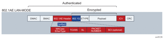
Forwarding a MACsec packet uses the destination MAC address, which is in clear text.
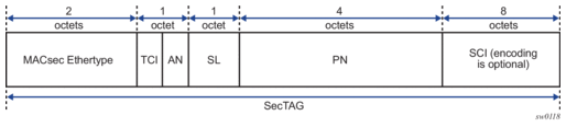
2.3.2.1.1. MACsec 802.1AE Header (SecTAG)
The 802.1AE header has a security tag (SecTAG) which includes:
- the association number within the channel
- the packet number to provide a unique initialization vector for encryption and authentication algorithms, as well as protection against replay attack
- an optional LAN-wide secure channel identifier
The SecTAG is identified by the MACsec EtherType and includes the following fields:
- TAG Control Information (TCI)
- Association Number (AN)
- Short Length (SL)
- Packet Number (PN)
- Optionally-encoded Secure Channel Identifier (SCI)
Figure 2 shows the format of the SecTAG.
Figure 2: SecTAG Format
2.3.2.1.2. MACsec Encryption Mode
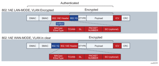
MACsec uses the following main modes of encryption:
- VLAN in clear text (WAN Mode)
- VLAN encrypted
The 802.1AE standard requires that the 802.1Q VLAN is encrypted. Some vendors provide the option of configuring MACsec on a port with VLAN in clear text. The 7210 SAS-K 2F6C4T and 7210 SAS-K 3SFP+ 8C support both modes on both 1GE and 10GE ports.
Figure 3 shows VLAN encrypted and VLAN in clear text.
Figure 3: 802.1 AE LAN/WAN Modes and VLAN Encrypted/Clear
2.3.2.1.2.1. MACsec Encryption per Traffic Flow Encapsulation Matching
MACsec can be applied to a selected subset of the port traffic, based on the type and value of the packet encapsulation. Configure the system to match and encrypt all encapsulated traffic arriving on a port, including untagged, single-tag, and double-tag. This is the default behavior of MACsec and the only option supported.
MKA PDUs are generated specifically for the traffic encapsulation type that is being matched.
2.3.2.1.3. MACsec Key Management Modes
Table 9 describes the key management modes in MACsec.
Table 9: MACsec Key Management Modes
Keying | Explanation | SR OS Support | Where Used |
Static SAK | Manually configures each node with a static SAK using CLI or NSP. | N/A | Switch to switch |
Static CAK PRE SHARED KEY | Uses dynamic MACsec Key Management (MKA) and uses a configured pre-shared key to derive the CAK. The CAK encrypts the SAK between two peers and authenticates the peers. | Supported | Switch to switch |
Dynamic CAK EAP Authentication | Uses dynamic MKA and an EAP MSK (Master System Key) to derive the CAK. The CAK encrypts the SAK between two peers and authenticates the peers. | Not Supported | Switch to switch |
Dynamic CAK MSK Distribution via RADIUS and EAP-TLS | MSKs are stored in the RADIUS server and distributed to the hosts via EAP-TLS. This is typically used in access networks where there are a large number of hosts using MACsec and connecting to an access switch. MKA uses MSK to derive the CAK. The CAK encrypts the SAK between 2 peers and authenticates the peers. | Not Supported | Host to switch |
2.3.2.1.4. MACsec Terminology
Figure 4 shows the main concepts used in MACsec for the static-CAK scenario.
Figure 4: MACsec Concepts for Static-CAK
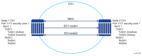
Table 10 describes MACsec terminology.
Table 10: MACsec Terminology
MACsec Term | Description |
Connectivity Association (CA) | A security relationship, established and maintained by the MKA, that comprises a fully connected subset of the service access points in stations attached to a single LAN that are to be supported by MACsec. |
MACsec Key Agreement Protocol (MKA) | Control protocol between MACsec peers, which is used for peer aliveness and encryption key distribution. MKA is responsible for discovering, authenticating, and authorizing the potential participants in a CA. |
MAC Security Entity (SecY) | Operates the MAC security protocol within a system. Manages and identifies the SC and the corresponding active SA. |
Port Access Entity (PAE) | The protocol entity associated with a port. May support the functionality of authenticator, supplicant, or both. |
Security Channel (SC) | Provides a unidirectional point-to-point or point-to-multipoint communication. Each SC contains a succession of SAs, and each SC has a different SAK. |
Security Association Key (SAK) | The key used to encrypt the datapath of MACsec. |
Security Association (SA) | A security relationship that provides security guarantees for frames transmitted from one member of a CA to the others. In the case of 2 SAs per SC, each with a different SAK, each SC comprises a succession of SAs. Each SA has an SC identifier, concatenated with a two-bit association number. The Secure Association Identifier (SAI) that has been created allows the receiving SecY to identify the SA, and thereby the SAK used to decrypt and authenticate the received frame. The AN (and the SAI) is only unique for the SAs that can be used or recorded by participating SecYs at any time. MKA creates and distributes SAKs to each of the SecYs in a CA. This key creation and distribution is independent of the cryptographic operation of each of the SecYs. The decision to replace one SA with its successor is made by the SecY that transmits using the SC, after MKA has informed it that all the other SecYs are prepared to receive using that SA. No notification, other than receipt of a secured frame with a different SAI, is sent to the receiver. A SecY must always be capable of storing SAKs for two SAs for each inbound SC, and of swapping from one SA to another without notice. Certain LAN technologies can reorder frames of different priority, so reception of frames on a single SC can use interleaved SA. |
2.3.2.1.5. MACsec Static CAK
MACsec uses SAs to encrypt packets. Each SA has a single SAK that contains the cryptographic operations used to encrypt the datapath PDUs.
SAK is the secret key used by an SA to encrypt the channel.
When enabled, MACsec uses a static CAK security mode, which has two security keys: a CAK that secures control plane traffic and a randomly generated SAK that secures data plane traffic. Both keys are used to secure the point-to-point or point-to-multipoint Ethernet link and are regularly exchanged between devices on each end of the Ethernet link.
Figure 5 shows MACsec generating the CAK.
Figure 5: MACsec Generating the CAK
The node initially needs to secure the control plane communication to distribute the SAKs between two or more members of a CA domain.
The control plane is secured using CAK, which is generated using one of the following methods:
- EAPoL
- pre-shared key (CAK and CKN values are configured using the CLI). The following CAK and CKN rules apply.
- CAK uses 32 hexadecimal characters for a 128-bit key, and 64 hexadecimal characters for a 256-bit key, depending on the algorithm used for control plane encryption; for example, aes-128-cmac or aes-256-cmac.
- CKN is a 32-octet character (64 hex) and is the name that identifies the CAK. This allows each of the MKA participants to select which CAK to use to process a received MKPDU. MKA places the following restrictions on the format of the CKN:
- it must comprise an integral number of octets, between 1 and 32 (inclusive)
- all potential members of the CA must use the same CKN
- CAK and CKN must match on peers to create a MACsec-secure CA.
Figure 6 shows MACsec control plane authentication and encryption.
Figure 6: MACsec Control Plane
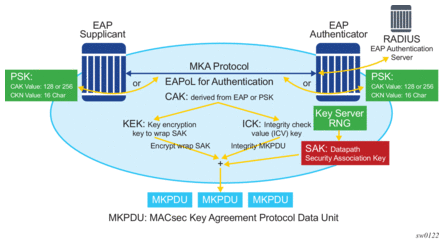
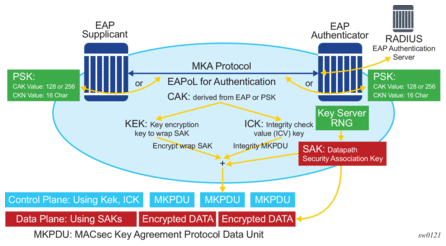
After the CAK is generated, it can obtain the following additional keys:
- KEK (Key Encryption Key)The KEK is used to wrap and encrypt the SAKs.
- ICK (Integrity Connection Value (ICV) Key)The ICK is used for an integrity check of each MKPDU send between two CAs.
The key server then creates a SAK and shares it with the CAs of the security domain, and that SAK secures all data traffic traversing the link. The key server periodically creates and shares a randomly created SAK over the point-to-point link for as long as MACsec is enabled.
The SAK is encrypted using the AES-CMAC, the KEK as the encryption key, and ICK as the integration key.
2.3.2.1.6. SAK Rollover
The SAK is regenerated after the following events:
- when a new host has joined the CA domain and MKA hellos are received from this host
- when the sliding window is reaching the end of its 32-bit or 64-bit length
- when a new PSK is configured and a rollover of PSK is executed
2.3.2.1.7. MKA
Each MACsec peer operates the MKA. Each node can operate multiple MKAs based on the number of CAs that it belongs to. Each instance of MKA is protected by a distinct secure CAK, that allows each Port Access Entity (PAE), or port, to ensure that information for a specific MKA instance is accepted only from other peers that also possess that CAK, therefore identifying themselves as members or potential members of the same CA. For a description of how the CAK identification is performed using CKN, see MACsec Static CAK.
2.3.2.1.7.1. MKA PDU Generation
Table 11 describes the MKA PDUs generated for different traffic encapsulation matches.
Table 11: MKA PDU Generation
Configuration | Configuration Example (<s-tag>.<c-tag>) | MKA Packet Generation | Traffic Pattern Match/Behavior | Supported on 7210 SAS |
All-encap | Config>port>ethernet>dot1x>macsec ca-name 10 | untagged MKA packet | Matches all traffic on port, including untagged, single-tag, and double-tag. Default behavior. | Yes |
UN-TAG | Config>port>ethernet>dot1x>macsec sub-port 1 encap-match untagged ca-name 2 | untagged MKA packet | Matches only untagged traffic on port | No |
802.1Q single S-TAG (specific S-TAG) | Config>port>ethernet>dot1x>macsec sub-port 2 encap-match dot1q 1 ca-name 3 | MKA packet generated with S-TAG=1 | Matches only single-tag traffic on port with tagID of 1 | No |
802.1Q single S-TAG (any S-TAG) | Config>port>ethernet>dot1x>macsec sub-port 3 encap-match dot1q * ca-name 4 | untagged MKA packet | Matches any dot1q single-tag traffic on port | No |
802.1ad double tag (both tag have specific TAGs) | Config>port>ethernet>dot1x>macsec sub-port 4 encap-match qinq 1.1 ca-name 5 | MKA packet generated with S-tag=1 and C-TAG=1 | Matches only double-tag traffic on port with service tag of 1 and customer tag of 1 | No |
802.1ad double tag (specific S-TAG, any C-TAG) | Config>port>ethernet>dot1x>macsec sub-port 6 encap-match qinq 1.* ca-name 7 | MKA packet generated with S-TAG=1 | Matches only double-tag traffic on port with service tag of 1 and customer tag of any | No |
802.1ad double tag (any S-TAG, any C-TAG) | Config>port>ethernet>dot1x>macsec sub-port 7 encap-match qinq *.* ca-name 8 | untagged MKA packet | Matches any double-tag traffic on port | No |
2.3.2.1.7.2. Tags in Clear Behavior by Traffic Encapsulation Types
By default, all tags are encrypted in CA. An MKA can be generated without any tags (un-tag), but the data being matched can be based on dot1q or q-in-q.
Table 12 describes how single or double tags in clear configuration under a CA affect different traffic flow encryptions.
Table 12: Tags in Clear Behavior
Configuration | Traffic Pattern Match/Behavior | CA Configuration: No Tag in Clear Text | CA Configuration: Single-tag in Clear Text | CA Configuration: Double-tag in Clear Text |
PORT | Matches all traffic on port, including untagged, single-tag, double-tag (default behavior) | MKA PDU: untagged Untagged traffic: encrypted Single-tag traffic: encrypted, no tag in clear Double-tag traffic: encrypted, no tag in clear | MKA PDU: untagged Untagged traffic: in clear Single-tag traffic: encrypted, single-tag in clear Double-tag traffic: encrypted, single-tag in clear | MKA PDU: untagged Untagged traffic: in clear Single-tag traffic: in clear Double-tag traffic: encrypted, double-tag in clear |
2.3.2.1.8. PSK
A peer may support the use of one or more pre-shared keys (PSKs). An instance of MKA operates for each PSK that is administratively configured as active.
A pre-shared key is either created by NSP or configured using the CLI. Each PSK is configured using the following fields:
- CKN
- CAK value
The CKN must be unique for each port among the configured sub-ports, and can be used to identify the key in subsequent management operations.
Each static CAK configuration can have two pre-shared key entries for rollover. The active PSK index dictates which CAK is being used for encrypting the MKA PDUs.
NSP has additional functionality to rollover and configure the PSK. The rollover using NSP can be based on a configured timer.
2.3.2.1.9. MKA Hello Timer
MKA uses a member identifier (MI) to identify each node in the CA domain.
A participant proves liveness to each of its peers by including the MI, together with an acceptably recent message number (MN), in an MKPDU.
To avoid a new participant having to respond to each MKPDU from each partner as it is received, or trying to delay its reply until it is likely that MI MN tuples have been received from all potential partners, each participant maintains and advertises both a live peers list and a potential peers list.
The live peers list includes peers that have included the participant MI and a recent MN in a recent MKPDU. The potential peers list includes all other peers that have transmitted an MKPDU that has been directly received by the participant or that were included in the live peers list of a MKPDU transmitted by a peer that has proved liveness. Peers are removed from each list when an interval of between MKA lifetime and MKA lifetime plus MKA Hello Time has elapsed since the participant's recent MN was transmitted. This time is sufficient to ensure that two or more MKPDUs will have been lost or delayed prior to the incorrect removal of a live peer.
Note:
|
Table 13 lists the MKA participant timer values.
Table 13: MKA Participant Timer Values
Timer Use | Timeout (parameter) | Timeout (parameter) |
Per participant periodic transmission, initialized on each transmission on expiry | MKA Hello Time or MKA Bounded Hello Time | 2.0 0.5 |
Per peer lifetime, initialized when adding to or refreshing the potential peers list or live peers list, expiry causes removal from the list | MKA Life Time | 6.0 |
Participant lifetime, initialized when participant created or following receipt of an MKPDU, expiry causes participant to be deleted | ||
Delay after last distributing a SAK, before the key server distributes a fresh SAK following a change in the live peers list while the potential peers list is still not empty |
2.3.2.1.10. MACsec Capability, Desire, and Encryption Offset
The IEEE 802.1x-2010 standard identifies the following fields in the MKA PDU:
- MACsec Capability
- Desire
MACsec capability signals whether MACsec is capable of integrity and confidentiality. For information about the basic settings for MACsec capability, see the encryption-offset command description.
Encryption offset of 0, 30, or 50 starts from the byte after the SecTAG (802.1AE header). Ideally, the encryption offset should be configured for IPv4 (offset 30) and IPv6 (offset 50) to leave the IP header in clear text. This allows routers and switches to use the IP header for LAG or ECMP hashing.
2.3.2.1.11. Key Server
The participants in an MKA instance that agree on a key server are responsible for the following:
- deciding on the use of MACsec
- cipher suite selection
- SAK generation and distribution
- SA assignment
- identifying the CA when two or more CAs merge
Each participant in an MKA instance uses the key server priority (an 8-bit integer) encoded in each MKPDU to agree on the key server. Each participant selects the live participant advertising the highest priority as its key server whenever the live peers list changes, provided that highest priority participant has not selected another as its key server or is unwilling to act as the key server.
If a key server cannot be selected, SAKs are not distributed. In the event of a tie for highest priority key server, the member with the highest priority SCI is chosen. For consistency with other uses of the SCI MAC address component as a priority, numerically lower values of the key server priority and SCI receive the highest priority.
| Note: Each SC is identified by an SCI that comprises a globally unique MAC address, and a port identifier unique within the system that has been allocated that address. |
2.3.2.1.12. SA Limits and Network Design
Each MACsec device supports 64 Tx-SAs and 64 Rx-SAs. An SA (Security Association) is the key to encrypt or decrypt the data.
As defined in IEEE 802.1AE, each SecY contains an SC. An SC is a unidirectional concept; for example, Rx-SC or Tx-SC. Each SC contains at least one SA for encryption on Tx-SC and decryption on Rx-SC. Also, for extra security, each SC should be able to roll over the SA, therefore, Nokia recommends for each SC to have two SAs for rollover purposes.
MACsec PHY is known as a MACsec security zone. Each MACsec security zone supports 64 Tx-SAs and 64 Rx-SAs. Assuming two SAs for each SC for SA rollover, each zone supports 32 Rx-SCs and 32 Tx-SCs.
Table 14 describes the port mapping to security zones.
Table 14: Port Mapping to Security Zone
Platform | Ports in Security Zone 1 | Ports in Security Zone 2 | Ports in Security Zone 3 | SA Limit per Security Zone |
7210 SAS-K 2F6C4T | Ports 1, 2, 3, 4 | Ports 5, 6, 7, 8 | Ports 9, 10, 11, 12 | Rx-SA = 64 Tx-SA = 64 |
7210 SAS-K 3SFP+ 8C | Ports 1, 2, 3, 4 (1, 2, and 3 are 10GE ports) | Ports 5, 6, 7, 8 | Ports 9, 10, 11 | Rx-SA = 64 Tx-SA = 64 |
2.3.2.1.13. P2P (Switch-to-Switch) Topology
In a point-to-point topology, each router needs a single security zone, a single Tx-SC for encryption, and a single Rx-SC for decryption. Each SC has two SAs. In total, for point-to-point topology, four SAs are needed: two Rx-SAs for Rx-SC1 and two Tx-SAs for Tx-SC1.
Figure 7 shows the P2P topology.
Figure 7: P2P (Switch-to-Switch) Topology
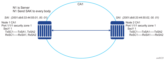
2.3.2.1.14. P2MP (Switch to Switch) Topology
In a multi-point topology with N nodes, each node needs a single Tx-SC and N Rx-SC, one for each one of the peers. As such, 64 maximum Rx-SAs for each security zone translates to 32 Rx-SCs, which breaks down to only 32 peers; for example, only 33 nodes in the multipoint topology for each security zone. So from the perspective of each node, there is one Tx-SC and 32 Rx-SCs.
As shown in Figure 8, when the 34th node joins the multi-point topology, the other 33 nodes that are already part of this domain do not have SAs to create an Rx-SC for this 34th node; however, the 34th node has a Tx-SC and can accept 32 peers. The 34th node starts to transmit and encrypt the PDUs based on its Tx-SC. However, because all other nodes do not have as SC for this SAI, all Rx PDUs are dropped.
Figure 8: P2MP Topology
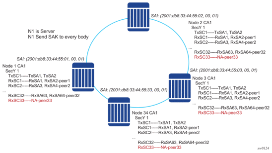
Nokia recommends that a multicast domain, for a single security zone, should not exceed 32 peers, or the summation of all the nodes in a security zone CA domain should not exceed 33. This is the same as if a security zone has four CAs; the summation of all nodes in the four CAs should be 33 or less.
2.3.2.1.15. SA Exhaustion Behavior
A security zone has 64 Rx-SAs and 64 Tx-SAs, as described in SA Limits and Network Design. Two Rx-SAs are used for each Rx-SC for rollover purposes, and two Tx-SAs are used for Tx-SC for rollover purposes. This translates to 32 peers for each security zone.
Under each port, you can configure a max-peer parameter to assign the number of peers allowed on that port.
| Note: You must ensure that the number of peers does not exceed the limit of maximum peers per security zone or maximum peers per port; for example, exceeds the port max-peer parameter. |
If the maximum peer is exceeded, the peer connectivity becomes random. In the case of a node failure or packet loss, peers join the CA randomly, on a first-come-first-served basis.
| Caution: Nokia strongly recommends that the maximum peer value is not exceeded per-security zone or port. |
2.3.2.1.16. Clear Tag Mode
In most Layer 2 networks, MAC forwarding is done using a destination MAC address. The 802.1AE standard requires that any field after source and destination MAC address and after the SecTAG must be encrypted. This includes the 802.1Q tags. In some VLAN switching networks, it might be desired to leave the 802.1Q tag in clear text.
7210 SAS allows the configuration of 802.1Q tag in clear text by placing the 802.1Q tag before the SecTAG, or encrypts it by placing it after the SecTAG.
Table 15 lists the MACsec encryption of 802.1Q tags when the clear-tag is configured.
Table 15: MACsec Encryption of 802.1Q Tagswith Clear-tag Configured
Unencrypted Format | Clear-tag-mode Configuration | Pre-encryption (Tx) | Pre-decryption (Rx) |
Single tag (dot1q) | Single-tag | DA, SA, TPID, VID, Etype | DA, SA, TPID, VID, SecTAG |
Single tag (dot1q) | Double-tag | DA, SA, TPID, VID, Etype | DA, SA, TPID, VID, SecTAG |
Double tag (q-in-q) | Single-tag | DA, SA, TPID1, VID1, IPID2, VID2, Etype | DA, SA, TPID1, VID1, SecTAG |
Double tag (q-in-q) | Double-tag | DA, SA, TPID1, VID1, IPID2, VID2, Etype | DA, SA, TPID1, VID1, IPID2, VID2, SecTAG |
2.3.2.1.17. 802.1X Tunneling and Multihop MACsec
MACsec is an Ethernet packet and, as with any Ethernet packet, can be forwarded through multiple switches using Layer 2 forwarding. The encryption and decryption of the packets is done using the 802.1x (MKA) capable ports.
To ensure that MKA is not terminated on an intermediate switch or router, you can enable 802.1x tunneling on the corresponding port.
Check to see if tunneling is enabled using the following command:
By enabling tunneling, the 802.1x MKA packets transit that port without being terminated, because such MKA negotiation does not occur on a port that has 802.1x tunneling enabled.
2.3.2.1.18. EAPoL Destination Address
The MKA packets are transported over EAPoL with a multicast destination MAC address.
In cases where a point-to-point connection from the MKA to a peer node over a Layer 2 multihop cloud is required, you can set the EAPoL destination MAC address to the peer MAC address. This forces the MKA to traverse multiple nodes and establish an MKA session with the specific peer.
2.3.2.1.19. Mirroring Consideration
Mirroring is performed prior to MACsec encryption. Therefore, if a port is MACsec-enabled and is also being mirrored, all the mirror packets are in clear text.
2.3.3. Ethernet Combo Ports on 7210 SAS-K 2F1C2T, 7210 SAS-K 2F6C4T, and 7210 SAS-K 3SFP+ 8C
The 7210 SAS-K 2F1C2T, 7210 SAS-K 2F6C4T, and 7210 SAS-K 3SFP+ 8C support combo ports. The combo port provides two physical interface options to the user. One option is to configure it as an SFP port allowing for fiber-based connectivity and speeds of 100/1000 Mb/s with the advantages of using suitable optics for longer reach. The other option is to configure it as a fixed copper port, which provides cheaper connectivity for shorter reach. The SFP port support 100/1000 Mb/s speeds and the copper port can support 10/100/1000Mbps speed. The combo port can be configured either as an SFP port or a copper port. Both interfaces cannot be used simultaneously.
- 7210 SAS-K 2F1C2T provide one Combo port
- 7210 SAS-K 2F6C4T provides six Combo ports
- 7210 SAS-K 3SFP+ 8C provides eight Combo ports
2.4. Link Layer Discovery Protocol (LLDP)
The IEEE 802.1ab Link Layer Discovery Protocol (LLDP) standard defines protocol and management elements suitable for advertising information to stations attached to the same IEEE 802 LAN. The protocol facilitates the identification of stations connected by IEEE 802 LANs or MANs, their points of interconnection, and access points for management protocols.
The LLDP helps the network operators to discover topology information. This information is used to detect and resolve network problems and inconsistencies in the configuration.
The following list is the information included in the protocol defined by the IEEE 802.1ab standard:
- Connectivity and management information about the local station to adjacent stations on the same IEEE 802 LAN is advertised.
- Network management information from adjacent stations on the same IEEE 802 LAN is received.
- Operates with all IEEE 802 access protocols and network media.
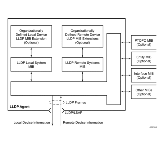
- Network management information schema and object definitions that suitable for storing connection information about adjacent stations is established.
- Provides compatibility with a number of MIBs. For more information, see Figure 9.
Figure 9 shows LLDP internal architecture for a network node.
Figure 9: LLDP Internal Architecture for a Network Node
To detect and address network problems and inconsistencies in the configuration, the network operators can discover the topology information using LLDP. The Standard-based tools address the complex network scenarios where multiple devices from different vendors are interconnected using Ethernet interfaces.
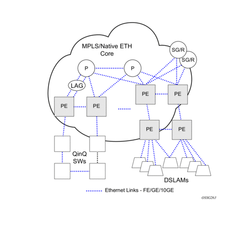
Figure 10 shows an MPLS network that uses Ethernet interfaces in the core or as an access/handoff interfaces to connect to different kind of Ethernet enabled devices such as service gateway/routers, QinQ switches DSLAMs, or customer equipment.
The topology information of the network in Figure 10 can be discovered if, IEEE 802.1ab LLDP is running on each of the Ethernet interfaces in network.
Figure 10: Generic Customer Use Case For LLDP
2.4.1. LLDP Protocol Features
LLDP is an unidirectional protocol that uses the MAC layer to transmit specific information related to the capabilities and status of the local device. Separately from the transmit direction, the LLDP agent can also receive the same kind of information for a remote device which is stored in the related MIBs.
LLDP does not contain a mechanism for soliciting specific information from other LLDP agents, nor does it provide a specific means of confirming the receipt of information. LLDP allows the transmitter and the receiver to be separately enabled, making it possible to configure an implementation so the local LLDP agent can either transmit only or receive only, or can transmit and receive LLDP information.
The information fields in each LLDP frame are contained in a LLDP Data Unit (LLDPDU) as a sequence of variable length information elements, that each include type, length, and value fields (known as TLVs), where:
- Type identifies what kind of information is being sent.
- Length indicates the length of the information string in octets.
- Value is the actual information that needs to be sent (for example, a binary bit map or an alphanumeric string that can contain one or more fields).
Each LLDPDU contains four mandatory TLVs and can contain optional TLVs as selected by network management:
- Chassis ID TLV
- Port ID TLV
- Time To Live TLV
- Zero or more optional TLVs, as allowed by the maximum size of the LLDPDU
- End Of LLDPDU TLV
The chassis ID and the port ID values are concatenated to form a logical identifier that is used by the recipient to identify the sending LLDP agent/port. Both the chassis ID and port ID values can be defined in a number of convenient forms. When selected however, the chassis ID/port ID value combination remains the same as long as the particular port remains operable.
A non-zero value in the TTL field of the Time To Live TLV tells the receiving LLDP agent how long all information pertaining to this LLDPDU identifier will be valid so that all the associated information can later be automatically discarded by the receiving LLDP agent if the sender fails to update it in a timely manner. A zero value indicates that any information pertaining to this LLDPDU identifier is to be discarded immediately.
A TTL value of 0 can be used, for example, to signal that the sending port has initiated a port shutdown procedure. The End Of LLDPDU TLV marks the end of the LLDPDU.
The implementation defaults to setting the port-id field in the LLDP OAMPDU to tx-local. This encodes the port-id field as ifIndex (sub-type 7) of the associated port. This is required to support some releases of SAM. SAM may use the ifIndex value to properly build the Layer Two Topology Network Map. However, this numerical value is difficult to interpret or readily identify the LLDP peer when reading the CLI or MIB value without SAM. Including the port-desc option as part of the tx-tlv configuration allows an ALU remote peer supporting port-desc preferred display logic to display the value in the port description TLV instead of the port-id field value. This does not change the encoding of the port-id field. That value continues to represent the ifIndex. In some environments, it may be important to select the specific port information that is carried in the port-id field. The operator has the ability to control the encoding of the port-id information and the associated subtype using the port-id-subtype option. Three options are supported for the port-id-subtype:
tx-if-alias — Transmit the ifAlias String (subtype 1) that describes the port as stored in the IFMIB, either user configured description or the default entry (that is,10/100/Gig ethernet SFP)
tx-if-name — Transmits the ifName string (subtype 5) that describes the port as stored in the IFMIB, ifName info.
tx-local — The interface ifIndex value (subtype 7)
IPv6 (address subtype 2) and IPv4 (address subtype 1) LLDP System Management addresses are supported.
2.4.1.1. LLDP Tunneling for Epipe Service
Customers who subscribe to Epipe service consider the Epipe as a wire, and run LLDP between their devices which are located at each end of the Epipe. To facilitate this, the 7210 devices support tunneling of LLDP frames that use the nearest bridge destination MAC address.
If enabled using the command tunnel-nearest-bridge-dest-mac, all frames received with the matching LLDP destination mac address are forwarded transparently to the remote end of the Epipe service. To forward these frames transparently, the port on which tunneling is enabled must be configured with NULL SAP and the NULL SAP must be configured in an Epipe service. Tunneling is not supported for any other port encapsulation or other services.
Additionally, before enabling tunneling, admin status for LLDP dest-mac nearest-bridge must be set to disabled or Tx only, using the command admin-status available under config>port>ethernet>lldp>destmac-nearest-bridge. If the admin-status for dest-mac nearest-bridge is set to receive and process nearest-bridge LLDPDUs (that is, if either rx or tx-rx is set), then it overrides the tunnel-nearest-bridge-dest-mac command.
The following table lists the behavior for LLDP with different values set in use for admin-status and when tunneling is enabled or disabled:
| Note: Transparent forwarding of LLDP frames can be achieved using the standard defined mechanism when using the either nearest-non-tmpr or the nearest-customer as the destination MAC address in the LLDP frames. It is recommended that the customers use these MAC address where possible to conform to standards. This command allows legacy LLDP implementations that do not support these additional destinations MAC addresses to tunnel LLDP frames that use the nearest-bridge destination MAC address. |
2.5. Port Loopback for Ethernet Ports
The 7210 SAS supports port loopback for Ethernet ports. There are two flavors of port loopback commands - port loopback without mac-swap and port loopback with mac-swap. Both these commands are helpful for testing the service configuration and measuring performance parameters such as throughput, delay, and jitter on service turn-up. Typically, a third-party external test device is used to inject packets at desired rate into the service at a central office location.
The following sections describe the port loopback functionality.
2.5.1. Port Loopback without MAC Swap
| Note: Port loopback without MAC swap is supported on all 7210 SAS platforms as described in this document. |
When the port loopback command is enabled, the system enables PHY/MAC loopback on the specified port. All the packets are sent out the port configured for loopback and received back by the system. On ingress to the system after the loopback, the node processes the packets as per the service configuration for the SAP.
This is recommended for use with only Epipe services. This command affects all the services configured on the port, therefore the user is advised to ensure all the configuration guidelines mentioned for this feature in the command description are followed.
2.5.2. Port Loopback with MAC Swap
| Note: Port loopback with MAC swap is only supported on the 7210 SAS-D and 7210 SAS-Dxp. |
The 7210 SAS provides port loopback support with MAC swap. When the port loopback command is enabled, the system enables PHY/MAC loopback on the specified port. All the packets are sent out the port configured for loopback and received back by the system. On ingress to the system after the loopback, the node swaps the MAC addresses for the specified SAP and the service. It only processes packets that match the specified source MAC address and destination MAC address, while dropping packets that do not match. It processes these packets as per the service configuration for the SAP.
This is recommended for use with only VPLS and Epipe services. This command affects all the services configured on the port, therefore the user is advised to ensure all the configuration guidelines mentioned for this feature in the command description are followed.
2.5.3. Per-SAP Loopback with MAC Swap
| Note: Per-SAP loopback with MAC swap is only supported on the 7210 SAS-K 2F1C2T, 7210 SAS-K 2F6C4T, and 7210 SAS-K 3SFP+ 8C. |
The 7210 SAS-K 2F1C2T, 7210 SAS-K 2F6C4T, and 7210 SAS-K 3SFP+ 8C provide per-SAP loopback support with MAC swap. When the SAP loopback command is enabled, all the packets that are sent out the SAP configured with loopback are looped back at the egress of the SAP back into the ingress of the SAP. The node swaps the MAC addresses before the packet hits the ingress of the SAP. After it is received back at SAP ingress, it processes these packets as per the service configuration for the SAP. Only traffic sent out of the test SAP is looped back. The loopback does not affect other SAPs and services configured on the same port. Per-SAP loopback is supported for use with both VPLS and Epipe services.
2.6. LAG
Based on the IEEE 802.3ax standard (formerly 802.3ad), Link Aggregation Groups (LAGs) can be configured to increase the bandwidth available between two network devices, depending on the number of links installed. LAG also provides redundancy in the event that one or more links participating in the LAG fail. All physical links in a specific LAG links combine to form one logical interface.
Packet sequencing must be maintained for any specific session. The hashing algorithm deployed by Nokia routers is based on the type of traffic transported to ensure that all traffic in a flow remains in sequence while providing effective load sharing across the links in the LAG.
LAGs must be statically configured or formed dynamically with Link Aggregation Control Protocol (LACP). The optional marker protocol described in IEEE 802.3ax is not implemented. LAGs can be configured on access uplink and access ports.
2.6.1. LAG Features
Hardware capabilities:
- The LAG load sharing is executed in hardware, which provides line rate forwarding for all port types.
Software capabilities:
- Conforms to the IEEE LAG implementation.
2.6.2. Configuring LAGs
LAG configuration guidelines include:
- The 7210 SAS-D and 7210 SAS-Dxp support up to four 1GE ports in a LAG. The 7210 SAS-Dxp also supports up to two 10GE ports in a LAG.
- The 7210 SAS-K 2F1C2T and 7210 SAS-K 2F6C4T support up to three 1GE ports in a LAG.
- The 7210 SAS-K 3SFP+ 8C supports up to three 1GE ports or two 10GE ports in a LAG.
- Ports can be added or removed from the LAG while the LAG and its ports (other than the port being removed) remain operational. When ports to and from the LAG are added or removed, the hashing algorithm is adjusted for the new port count.
- The show commands display physical port statistics on a port-by-port basis, or the entire LAG can be displayed.
- On the 7210 SAS-K 2F1C2T, 7210 SAS-K 2F6C4T, and 7210 SAS-K 3SFP+ 8C, a single set of counters is used to account for the traffic received on the LAG.
- LAG is supported on Ethernet ports.
- Ports of a particular LAG can be of different types, but they must be the same speed and duplex. To guarantee the same port speed is used for all ports in a LAG, autonegotiation must be disabled or set to limited mode to ensure only a specific speed is advertised.
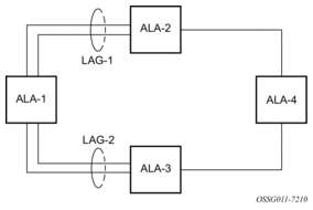
Figure 11 shows traffic routed between ALA-1 and ALA-2 as a LAG consisting of four ports.
Figure 11: LAG Configuration
2.6.3. LAG and QoS Policies on 7210 SAS-D and 7210 SAS-Dxp
On the 7210 SAS-D and 7210 SAS-Dxp, an ingress QoS policy is applied to the aggregate traffic that is received on all the member ports of the LAG. For example, if an ingress policy is configured with a policer of PIR 100Mbps, for a SAP configured on a LAG with two ports, then the policer limits the traffic received through the two ports to a maximum of 100Mbps.
On the 7210 SAS-D and 7210 SAS-Dxp, an egress QoS policy parameters are applied to all the ports that are members of the LAG (all ports get the full SLA). For example, if an egress policy is configured with a queue shaper rate of PIR 100Mbps, and applied to an access-uplink or access LAG configured with two port members, then each port would send out 100 Mbps of traffic for a total of 200Mbps of traffic out of the LAG. The advantage of this method over a scheme where the PIR is divided equally among all the member ports of the LAG is that, a single flow can use the entire SLA. The disadvantage is that, the overall SLA can be exceeded if the flows span multiple ports.
2.6.4. LAG and QoS Policies on 7210 SAS-K 2F1C2T, 7210 SAS-K 2F6C4T, and 7210 SAS-K 3SFP+ 8C
On the 7210 SAS-K 2F1C2T, 7210 SAS-K 2F6C4T, and 7210 SAS-K 3SFP+ 8C, an ingress QoS policy is applied to the aggregate traffic that is received through all the member ports of the LAG and mapped to that service entity (for example: access-uplink port). For example, if an ingress policy is configured with a queue shaper rate of PIR 100Mbps for an access-uplink LAG configured with two ports, then the queue shaper limits the traffic received through the two ports to a maximum of 100Mbps.
On the 7210 SAS-K 2F1C2T,7210 SAS-K 2F6C4T, and 7210 SAS-K 3SFP+ 8C, egress QoS policy parameters are applied to all the ports that are members of the LAG (all ports get the full SLA). For example, if an egress policy is configured with a queue shaper rate of PIR 100Mbps, and applied to an access-uplink LAG configured with two port members, then each port can send out 100 Mbps of traffic for a total of 200Mbps of traffic out of the LAG (assuming flows are distributed among the 2 ports). The advantage of this method over a scheme where the PIR is divided equally among all the member ports of the LAG is that a single flow can use the entire SLA. The disadvantage is that the overall SLA can be exceeded if the flows span multiple ports.
2.6.5. Port Link Damping
Hold time controls enable port link damping timers that reduce the number of link transitions reported to upper layer protocols.
The 7210 SAS port link damping feature guards against excessive port transitions. Any initial port transition is immediately advertised to upper layer protocols, but any subsequent port transitions are not advertised to upper layer protocols until a configured timer has expired.
An “up” timer controls the dampening timer for link up transitions, and a “down” timer controls the dampening timer for link down transitions.
2.6.6. LACP
Generally, link aggregation is used for two purposes: provide an increase in bandwidth and/or provide redundancy. Both aspects are addressed by aggregating several Ethernet links in a single LAG.
LACP enhancements allow active lag-member selection based on particular constrains. The mechanism is based on the IEEE 802.3ax standard so interoperability is ensured.
2.6.7. LAG and ECMP Hashing
| Note: Refer to the 7210 SAS-D, Dxp, K 2F1C2T, K 2F6C4T, K 3SFP+ 8C Router Configuration Guide for more information about ECMP support for 7210 SAS platforms. |
When a requirement exists to increase the available bandwidth for a logical link that exceeds the physical bandwidth or add redundancy for a physical link, typically one of the following methods is applied:
- equal cost multi-path (ECMP)
- Link Aggregation (LAG)
A 7210 SAS can deploy both methods at the same time, meaning it can use ECMP of two or more Link Aggregation Groups (LAG) or single links.The Nokia implementation supports per flow hashing used to achieve uniform loadspreading and per service hashing designed to provide consistent per service forwarding. Depending on the type of traffic that needs to be distributed into an ECMP or a LAG, different variables are used as input to the hashing algorithm.
The following tables list the packets used for hashing on 7210 SAS platforms.
2.6.7.1. LAG Hashing Algorithm for the 7210 SAS-D
Table 16 describes the packet fields used for hashing for services configured on the 7210 SAS-D.
| Note: The following notes apply to Table 16:
|
Table 16: LAG Hashing Algorithm for Services Configured on 7210 SAS-D
Traffic Type | Packet Fields Used | ||||||||
BDA | BSA | EtherType | Ingress Port-ID | ISID | Source and Destination | VLAN | |||
MAC | IP | L4 Ports | |||||||
VPLS Service SAP to SAP | |||||||||
IP traffic (learned) | ✓ | ✓ | |||||||
IP traffic (unlearned) | ✓ | ✓ | ✓ | ||||||
PBB traffic (learned) | ✓ | ✓ | ✓ | ||||||
PBB traffic (unlearned) | ✓ | ✓ | ✓ | ✓ | |||||
Non-IP traffic (learned) | ✓ | ✓ | ✓ | ||||||
Non-IP traffic (unlearned) | ✓ | ✓ | ✓ | ✓ | |||||
Epipe Service SAP to SAP | |||||||||
IP traffic | ✓ | ✓ | ✓ | ||||||
PBB traffic | ✓ | ✓ | ✓ | ✓ | |||||
Non-IP traffic | ✓ | ✓ | ✓ | ✓ | |||||
IES service (IPv4): IES SAP to IES SAP | |||||||||
IPv4 unicast traffic | ✓ | ✓ | |||||||
2.6.7.2. LAG Hashing Algorithm for the 7210 SAS-Dxp
Table 17 describes the packet fields used for hashing for services configured on the 7210 SAS-Dxp.
| Note: The following notes apply to Table 17:
|
Table 17: LAG Hashing Algorithm for Services Configured on 7210 SAS-Dxp
Traffic Type | Packet Fields Used | ||||||||
BDA | BSA | EtherType | Ingress Port-ID | ISID | Source and Destination | VLAN | |||
MAC | IP | L4 Ports | |||||||
VPLS Service SAP to SAP | |||||||||
IP traffic (learned) | ✓ | ✓ | |||||||
IP traffic (unlearned) | ✓ | ||||||||
PBB traffic (learned) | ✓ | ✓ | |||||||
PBB traffic (unlearned) | ✓ | ✓ | ✓ | ||||||
Non-IP traffic (learned) | ✓ | ✓ | |||||||
Non-IP traffic (unlearned) | ✓ | ✓ | |||||||
Epipe Service SAP to SAP | |||||||||
IP traffic | ✓ | ||||||||
PBB traffic | ✓ | ✓ | ✓ | ||||||
Non-IP traffic | ✓ | ✓ | |||||||
IES service (IPv4): IES SAP to IES SAP | |||||||||
IPv4 unicast traffic | ✓ | ✓ | |||||||
2.6.7.3. LAG Hashing Algorithm for the 7210 SAS-K 2F1C2T
Table 18 describes the packet fields used for hashing for services configured on the 7210 SAS-K 2F1C2T.
| Note: The following notes apply to Table 18:
|
Table 18: LAG Hashing Algorithm for Services Configured on 7210 SAS-K 2F1C2T
Traffic Type | Packet Fields Used | ||||||||
BDA | BSA | Ingress Port-ID | IP Protocol | Source and Destination | VLAN | ||||
MAC | IP | L4 Ports | Outer | Inner | |||||
VPLS Service SAP to SAP | |||||||||
IP traffic (learned and unlearned) | ✓ | ✓ | ✓ | ✓ | ✓ | ||||
PBB traffic (learned and unlearned) | ✓ | ✓ | ✓ | ✓ | ✓ | ||||
MPLS traffic (learned and unlearned) | ✓ | ✓ 1 | ✓ | ✓ | |||||
Non-IP traffic (learned and unlearned) | ✓ | ✓ | ✓ | ✓ | |||||
Epipe Service SAP to SAP | |||||||||
IP traffic | ✓ | ✓ | ✓ | ✓ | ✓ | ||||
PBB traffic | ✓ | ✓ | ✓ | ✓ | ✓ | ||||
MPLS traffic | ✓ | ✓ 1 | ✓ | ✓ | |||||
Non-IP traffic | ✓ | ✓ | ✓ | ✓ | |||||
- The outer MAC of the Ethernet packet that encapsulates an MPLS packet
Note:
2.6.7.4. LAG Hashing Algorithm for the 7210 SAS-K 2F6C4T and 7210 SAS-K 3SFP+ 8C
Table 19 describes the packet fields used for hashing for services configured on the 7210 SAS-K 2F6C4T and 7210 SAS-K 3SFP+ 8C.
| Note: The following notes apply to Table 19:
|
Table 19: LAG Hashing Algorithm for Services Configured on 7210 SAS-K 2F6C4T and 7210 SAS-K 3SFP+ 8C
Traffic Type | Packet Fields Used | |||||||
Ingress Port-ID | IP Protocol | MPLS Label Stack | Source and Destination | VLAN | ||||
MAC | IP | L4 Ports | Outer | Inner | ||||
VPLS Service SAP to SAP | ||||||||
IP traffic (learned and unlearned) | ✓ | ✓ | ✓ | ✓ | ✓ | |||
MPLS traffic (learned and unlearned) | ✓ | ✓ 1 | ✓ | ✓ | ||||
Non-IP traffic (learned and unlearned) | ✓ | ✓ | ✓ | ✓ | ||||
VPLS Service SAP to SDP | ||||||||
IP traffic (learned and unlearned) | ✓ | ✓ | ✓ | ✓ | ✓ | |||
MPLS traffic | ✓ | ✓ 1 | ✓ | ✓ | ||||
Non-IP traffic (learned and unlearned) | ✓ | ✓ | ✓ | ✓ | ||||
VPLS Service SDP to SAP 2 | ||||||||
IP traffic (learned and unlearned) | ✓ | ✓ | ✓ | ✓ | ||||
Non-IP traffic (learned and unlearned) | ✓ | ✓ | ||||||
VPLS Service SDP to SDP 2 | ||||||||
IP traffic (learned and unlearned) | ✓ | ✓ | ✓ | ✓ | ||||
Non-IP traffic (learned and unlearned) | ✓ | ✓ | ||||||
Epipe Service SAP to SAP | ||||||||
IP traffic | ✓ | ✓ | ✓ | ✓ | ✓ | |||
MPLS traffic | ✓ | ✓ 1 | ✓ | ✓ | ||||
Non-IP traffic | ✓ | ✓ | ✓ | ✓ | ||||
Epipe Service SAP to SDP | ||||||||
IP traffic | ✓ | ✓ | ✓ | ✓ | ✓ | |||
MPLS traffic | ✓ | ✓ 1 | ✓ | ✓ | ||||
Non-IP traffic | ✓ | ✓ | ✓ | ✓ | ||||
Epipe Service SDP to SAP 2 | ||||||||
IP traffic (learned and unlearned) | ✓ | ✓ | ✓ | ✓ | ||||
Non-IP traffic (learned and unlearned) | ✓ | ✓ | ||||||
MPLS - LSR | ||||||||
All traffic | ✓ | ✓ 3 | ✓ | |||||
IES Service (IPv4) IES SAP to IES SAP | ||||||||
— | ✓ | ✓ |
| ✓ 4 | ✓ | ✓ | ||
IES Service (IPv6) IES SAP to IES SAP | ||||||||
— | ✓ | ✓ |
| ✓ 4 | ✓ | ✓ | ||
IES Service (IPv4) IES SAP to IPv4 network port interface | ||||||||
— | ✓ | ✓ |
| ✓ 4 | ✓ | ✓ | ||
IES Service (IPv6) IES SAP to IPv6 network port interface | ||||||||
— | ✓ | ✓ |
| ✓ 4 | ✓ | ✓ | ||
IES Service (IPv4) interface IPv4 network port interface to IES SAP | ||||||||
— | ✓ | ✓ |
| ✓ 4 | ✓ | ✓ | ||
IES Service (IPv6) IPv6 network port interface to IES SAP | ||||||||
— | ✓ | ✓ |
| ✓ 4 | ✓ | ✓ | ||
Network port (IPv4) interface IPv4 network interface to IPv4 network interface | ||||||||
— | ✓ | ✓ |
| ✓ 4 | ✓ | ✓ | ||
Network port (IPv6) interface IPv6 network interface to IPv6 network interface | ||||||||
— | ✓ | ✓ |
| ✓ 4 | ✓ | ✓ | ||
VPRN SAP to SAP, SDP to SAP, SAP to SDP | ||||||||
— | ✓ | ✓ |
| ✓ 4 | ✓ | ✓ | ||
- The outer MAC of the Ethernet packet that encapsulates an MPLS packet
- Traffic in the payload
- Four MPLS labels deep
- IPv4 and IPv6
Notes:
2.6.7.5. Packet Fields Used for Pseudowire Hash-label Generation on the 7210 SAS-K 2F6C4T and 7210 SAS-K 3SFP+ 8C
Table 20 describes the packet fields used by different services and traffic types to generate the PW hash label.
Table 20: Packet Fields Used for PW Hash-Label Generation on the 7210 SAS-K 2F6C4T and 7210 SAS-K 3SFP+ 8C
Traffic Type | Packet Fields Used | ||||||
Ingress Port-ID | IP Protocol | Source and Destination | VLAN | ||||
MAC | IP | L4 Ports | Outer | Inner | |||
VPLS and Epipe Services SAP to SDP | |||||||
IP traffic (learned and unlearned) | ✓ | ✓ | ✓ | ✓ | ✓ | ||
MPLS traffic (learned and unlearned) | ✓ | ✓ 1 | ✓ | ✓ | |||
Non-IP traffic (learned and unlearned) | ✓ | ✓ | ✓ | ✓ | |||
VPLS Services SDP to SDP | |||||||
IP traffic (learned and unlearned) | ✓ | ✓ | ✓ | ✓ | |||
Non-IP traffic (learned and unlearned) | ✓ | ✓ | |||||
- The outer MAC of the Ethernet packet that encapsulates MPLS packets
Note:
2.6.7.6. LDP ECMP Hashing Algorithm for the 7210 SAS-K 2F6C4T and 7210 SAS-K 3SFP+ 8C
Table 21 describes the packet fields used for LDP ECMP hashing for label edge router (LER) and label switching router (LSR) devices on the 7210 SAS-K 2F6C4T and 7210 SAS-K 3SFP+ 8C.
Table 21: LDP ECMP Hashing Algorithm for LER and LSR on the 7210 SAS-K 2F6C4T and 7210 SAS-K 3SFP+ 8C
Traffic Type | Packet Fields Used | |||||||
Ingress Port-ID | IP Protocol | MPLS Label Stack | Source and Destination | VLAN | ||||
MAC | IP | L4 Ports | Outer | Inner | ||||
VPLS and Epipe Services SAP to SDP (iLER) | ||||||||
IP traffic | ✓ | ✓ | ✓ | ✓ | ✓ | |||
MPLS traffic | ✓ | ✓ 1 | ✓ | ✓ | ||||
Non-IP traffic | ✓ | ✓ | ✓ | ✓ | ||||
LSR | ||||||||
MPLS traffic | ✓ | ✓ 2 | ✓ | |||||
- The outer MAC of the Ethernet packet that encapsulates MPLS packets
- Four MPLS labels deep
Notes:
2.6.8. Multi-Chassis LAG
This section describes the Multi-Chassis LAG (MC-LAG) concept. MC-LAG is an extension of a LAG concept that provides node-level redundancy in addition to link-level redundancy provided by “regular LAG”.
| Note: MC-LAG is supported on the 7210 SAS-K 2F6C4T and 7210 SAS-K 3SFP+ 8C. |
Typically, MC-LAG is deployed in a network-wide scenario and provides redundant connection between different end points. The whole scenario is then built by a combination of different mechanisms (for example, MC-LAG and redundant pseudowire to provide end-to-end (e2e) redundant point-to-point (p2p) connection or dual homing of CPE devices in Layer 2/3 VPNs).
2.6.8.1. Overview
MC-LAG is a method of providing redundant Layer 2/3 access connectivity that extends beyond link level protection by allowing two systems to share a common LAG end point.
The CPE/access node is connected with multiple links toward a redundant pair of Layer 2/3 access aggregation nodes such that both link and node level redundancy is provided. By using a multi-chassis LAG protocol, the paired Layer 2/3 aggregation nodes (referred to as the redundant-pair) appear to be a single node that is utilizing LACP toward the access node. The multi-chassis LAG protocol between the redundant-pair ensures a synchronized forwarding plane to and from the CPE/access node. It is used to synchronize the link state information between the redundant-pair nodes and provide correct LACP messaging to the CPE/access node from both redundant-pair nodes.
To ensure SLAs and deterministic forwarding characteristics between the CPE/access and the redundant-pair node, the multi-chassis LAG function provides an active/standby operation toward/from the CPE/access node. LACP is used to manage the available LAG links into active and standby states so that only links from one aggregation node are active at a time to and from the CPE/access node.
MC-LAG has the following characteristics.
- Selection of the common system ID, system-priority, and administrative-key are used in LACP messages to ensure that partner systems consider all links part of the same LAG.
- The selection algorithm is extended to allow the selection of the active subgroup.
- The subgroup definition in the LAG context is still local to the single box. Consequently, even when subgroups configured on two different systems have the same subgroup-id, they are still considered two separate subgroups within the specific LAG.
- The configuration of multiple subgroups per PE in an MC-LAG is supported.
- If there is a tie in the selection algorithm, for example, two subgroups with identical aggregate weight (or number of active links), the group that is local to the system with lower system LACP priority and LAG system ID is selected.
- Providing an inter-chassis communication channel allows the inter-chassis communication to support LACP on both systems. The communication channel enables the following functionality.
- It supports connections at the IP level that do not require a direct link between two nodes. The IP address configured at the neighbor system is one of the addresses of the system (interface or loop-back IP address).
- The communication protocol provides heartbeat mechanism to enhance robustness of the MC-LAG operation and detect node failures.
- It supports operator actions that force an operational change on nodes.
- The LAG group-ids do not have to match between neighbor systems. At the same time, multiple LAG groups between the same pair of neighbors is also allowed.
- It verifies that the physical characteristics, such as speed and auto-negotiation are configured and initiates operator notifications (traps) if errors exist. Consistency of MC-LAG configuration (system-id, administrative-key and system-priority) is provided. Load-balancing must be consistently configured on both nodes.
- Traffic over the signaling link is encrypted using a user-configurable message digest key.
- The MC-LAG function provides active/standby status to other software applications to build reliable solutions.
Figure 12 and Figure 13 show different combinations of supported MC-LAG attachments. The supported configurations can be divided into the following subgroups:
- dual-homing to remote PE pairs
- both end-points attached with MC-LAG
- one end-point attached
- dual-homing to local PE pair
- both end-points attached with MC-LAG
- one end-point attached with MC-LAG
- both end-points attached with MC-LAG to two overlapping pairs
Figure 12 shows dual homing to remote PE pairs.
Figure 12: MC-LAG L2 Dual Homing to Remote PE Pairs
Figure 13 shows dual homing to local PE pairs.
Figure 13: MC-LAG L2 Dual Homing to Local PE-Pairs
The forwarding behavior of the nodes is governed by the following principles. Note that the logical destination (actual forwarding decision) is primarily determined by the service (VPLS or VLL), and the following principle apply only if the destination or source is based on MC-LAG.
- Packets received from the network will be forwarded to all local active links of the specific destination-sap based on conversation hashing. If there are no local active links, the packets will be cross-connected to the inter-chassis pseudowire.
- Packets received from the MC-LAG sap will be forwarded to the active destination pseudo-wire or active local links of destination-sap. If no such objects are available at the local node, the packets will be cross-connected to inter-chassis pseudowire.
2.6.8.2. Point-to-Point Redundant Connection Across Layer 2/3 VPN Network
Figure 14 shows the connection between two CPE/access nodes across network based on Layer 2/3 VPN pseudo-wires. The connection between a CPE/access node and a pair of access aggregation PE routers is realized by MC-LAG. From the CPE/access node perspective, a redundant pair of access aggregation PE routers acts as a single partner in LACP negotiation. At any point in time, only one of the routers has active links in a specific LAG. The status of LAG links is reflected in the status signaling of pseudowires set between all participating PEs. The combination of active and standby states across LAG links and pseudowires give only one unique path between a pair of MSANs.
Note that the configuration in Figure 14 shows an example configuration of VLL connections based on MC-LAG. Specifically, it shows a VLL connection where the two ends (SAPs) are located on two different redundant-pairs. However, additional configurations are possible, for example:
- both ends of the same VLL connections are local to the same redundant-pair
- one end of the VLL endpoint is on a redundant-pair and the other on a single (local or remote) node
Figure 14: P2P Redundant Connection Through a Layer 2 VPN Network
2.6.8.3. Configuration Guidelines
The following guidelines apply to MC-LAG configurations.
- MC-LAG peer nodes must be of the same platform type. For example, 7210 SAS-K 2F6C4T can only peer with another 7210 SAS-K 2F6C4T, and 7210 SAS-K 3SFP+ 8C can only peer with another 7210 SAS-K 3SFP+ 8C. 7210 SAS-K 2F6C4T cannot be configured with 7210 SAS-K 3SFP+ 8C as its MC-LAG peer.
- MC-LAG is only supported when using MPLS uplinks with network ports. It is not supported with access-uplink ports.
- The 7210 SAS-K 2F6C4T and 7210 SAS-K 3SFP+ 8C can also be MC-LAG clients, with an active/standby LAG configuration used to dual-home to access-aggregation routers when using access-uplink ports. In this scenario the user has an option to provision the uplinks as access-uplink ports to dual-home into two aggregation PE routers that are configured as MC-LAG peers.
2.6.8.4. Configuring Multi-Chassis Redundancy
| Note: When configuring associated LAG ID parameters, the LAG must be in access mode and LACP must be enabled. |
Use the following syntax to configure multi-chassis redundancy features.
The following is a sample configuration output.
2.6.8.5. MC-LAG Support on 7210 SAS-D and 7210 SAS-K 2F1C2T
Multi-Chassis LAG (MC-LAG) is an extension of a LAG concept that provides node-level redundancy in addition to the link-level redundancy provided by “regular LAG”. Typically, MC-LAG is deployed network-wide, along with IP/MPLS, providing redundant connections between different access end points. In a typical MC-LAG deployment, a pair of nodes are configured to be MC-LAG peers (also referred to as MC-LAG servers), and access devices are connected to the MC-LAG peers using LAGs with active/standby LAG groups.
The 7210 SAS-D, 7210 SAS-K 2F1C2T, 7210 SAS-K 2F6C4T, and 7210 SAS-K 3SFP+ 8C platforms can be connected to an MC-LAG-enabled node, such as an MC-LAG server. In particular, these platforms allow for provisioning of links into subgroups in a LAG and support active/standby links. The MC-LAG solution can be achieved with or without subgroups configured.
2.6.9. G.8032 Protected Ethernet Rings
Ethernet ring protection switching provides ITU-T G.8032 specification compliance to achieve resiliency for Ethernet Layer 2 networks. G.8032 (Eth-ring) is built on Ethernet OAM and is often referred to as Ring Automatic Protection Switching (R-APS).
Refer to “G.8032 Protected Ethernet Rings” in the 7210 SAS-D, Dxp, K 2F1C2T, K 2F6C4T, K 3SFP+ 8C Services Guide for more information about Ethernet rings.
2.6.9.1. 802.1x Network Access Control
The Nokia 7210 SAS supports network access control of client devices (PCs, STBs, etc.) on an Ethernet network using the IEEE. 802.1x standard. 802.1x is known as Extensible Authentication Protocol (EAP) over a LAN network or EAPOL.
2.6.9.1.1. 802.1x Modes
The 7210 SAS supports port-based network access control for Ethernet ports only. Every Ethernet port can be configured to operate in one of three different operation modes, controlled by the port-control parameter:
- force-auth — Disables 802.1x authentication and causes the port to transition to the authorized state without requiring any authentication exchange. The port transmits and receives normal traffic without requiring 802.1x-based host authentication. This is the default setting.
- force-unauth — Causes the port to remain in the unauthorized state, ignoring all attempts by the hosts to authenticate. The switch cannot provide authentication services to the host through the interface.
- auto — Enables 802.1x authentication. The port starts in the unauthorized state, allowing only EAPOL frames to be sent and received through the port. Both the router and the host can initiate an authentication procedure that is described as follows. The port will remain in an unauthorized state (no traffic except EAPOL frames is allowed) until the first client is authenticated successfully. After this, traffic is allowed on the port for all connected hosts.
2.6.9.2. 802.1x Basics
- The supplicant — This is the end-user device that requests access to the network.
- The authenticator — Controls access to the network. Both the supplicant and the authenticator are referred to as PAEs.
- The authentication server — Performs the actual processing of the user information.
The authentication exchange is carried out between the supplicant and the authentication server, the authenticator acts only as a bridge. The communication between the supplicant and the authenticator is done through the Extended Authentication Protocol (EAP) over LANs (EAPOL). On the back end, the communication between the authenticator and the authentication server is done with the RADIUS protocol. The authenticator is therefore a RADIUS client, and the authentication server a RADIUS server.
The router initiates the procedure when the Ethernet port becomes operationally up, by sending a special PDU called EAP-Request/ID to the client. The client can also initiate the exchange by sending an EAPOL-start PDU, if it doesn't receive the EAP-Request/ID frame during bootup. The client responds on the EAP-Request/ID with a EAP-Response/ID frame, containing its identity (typically username + password).
After receiving the EAP-Response/ID frame, the router will encapsulate the identity information into a RADIUS AccessRequest packet, and send it off to the configured RADIUS server.
The RADIUS server checks the supplied credentials, and if approved will return an Access Accept message to the router. The router notifies the client with an EAP-Success PDU and puts the port in authorized state.
2.6.9.3. 802.1x Timers
The 802.1x authentication procedure is controlled by a number of configurable timers and scalars. There are two separate sets, one for the EAPOL message exchange and one for the RADIUS message exchange.
EAPOL timers:
- transit-period — Indicates how many seconds the Authenticator will listen for an EAP-Response/ID frame. If the timer expires, a new EAP-Request/ID frame will be sent and the timer restarted. The default value is 60. The range is 1 to 3600 seconds.
- supplicant-timeout — This timer is started at the beginning of a new authentication procedure (transmission of first EAP-Request/ID frame). If the timer expires before an EAP-Response/ID frame is received, the 802.1x authentication session is considered as having failed. The default value is 30. The range is 1 to 300.
- quiet-period — Indicates number of seconds between authentication sessions It is started after logoff, after sending an EAP-Failure message or after expiry of the supplicant-timeout timer. The default value is 60. The range is 1 to 3600.
RADIUS timer and scaler:
- max-auth-req — Indicates the maximum number of times that the router will send an authentication request to the RADIUS server before the procedure is considered as having failed. The default value is value 2. The range is 1 to 10.
- server-timeout — Indicates how many seconds the authenticator will wait for a RADIUS response message. If the timer expires, the access request message is sent again, up to max-auth-req times. The default value is 60. The range is 1 to 3600 seconds.
The router can also be configured to periodically trigger the authentication procedure automatically. This is controlled by the enable re-authentication and reauth-period parameters. Reauth-period indicates the period in seconds (since the last time that the authorization state was confirmed) before a new authentication procedure is started. The range of reauth-period is 1 to 9000 seconds (the default is 3600 seconds, one hour). Note that the port stays in an authorized state during the re-authentication procedure.
2.6.9.4. 802.1x Configuration and Limitations
Configuration of 802.1x network access control on the router consists of two parts:
- Generic parameters, which are configured under config>security>dot1x
- Port-specific parameters, which are configured under config>port>ethernet>dot1x
801.x authentication:
- Provides access to the port for any device, even if only a single client has been authenticated.
- Can only be used to gain access to a predefined Service Access Point (SAP). It is not possible to dynamically select a service (such as a VPLS service) depending on the 802.1x authentication information.
2.6.9.5. 802.1x Tunneling for Epipe Service
Customers who subscribe to Epipe service considers the Epipe as a wire, and run 802.1x between their devices which are located at each end of the Epipe.
| Note: This feature applies only to port-based Epipe SAPs because 802.1x runs at the port level not the VLAN level. Therefore such ports must be configured as null encapsulated SAPs. |
When 802.1x tunneling is enabled, the 802.1x messages received at one end of an Epipe are forwarded through the Epipe. When 802.1x tunneling is disabled (by default), 802.1x messages are dropped or processed locally according to the 802.1x configuration (shutdown or no shutdown).
Enabling 802.1x tunneling requires the 802.1x mode to be set to force-auth. Enforcement is performed at the CLI level.
2.7. 802.3ah OAM
802.3ah Clause 57 (EFM OAM) defines the Operations, Administration, and Maintenance (OAM) sub-layer, which provides mechanisms useful for monitoring link operation such as remote fault indication and remote loopback control. In general, OAM provides network operators the ability to monitor the health of the network and quickly determine the location of failing links or fault conditions. EFM OAM described in this clause provides data link layer mechanisms that complement applications that may reside in higher layers.
OAM information is conveyed in slow protocol frames called OAM protocol data units (OAMPDUs). OAMPDUs contain the appropriate control and status information used to monitor, test and troubleshoot OAM-enabled links. OAMPDUs traverse a single link, being passed between peer OAM entities, and as such, are not forwarded by MAC clients (like bridges or switches).
The following EFM OAM functions are supported:
- EFM OAM capability discovery.
- Active and passive modes.
- Remote failure indication — Handling of critical link events (for example, link fault, critical event, dying gasp)
- Loopback — A mechanism is provided to support a data link layer frame-level loopback mode. Both remote and local loopback modes are supported.
- Generation of dying gasp message on access uplink ports on power failure.
- EFM OAMPDU tunneling.
- Timer for EFM OAM in 500ms interval (minimum).
2.7.1. OAM Events
EFM OAM defines a set of events that may impact link operation. The following events are supported:
- Critical link events (defined in 802.3ah clause 57.2.10.1)
- Link fault: the PHY has determined a fault has occurred in the receive direction of the local DTE.
- Dying gasp: an unrecoverable local failure condition has occurred.
- Critical event: an unspecified critical event has occurred.
These critical link events are signaled to the remote DTE by the flag field in OAM PDUs.
The 7210 SAS does not generate EFM OAM PDUs with these flags except for the dying gasp flag. However, it supports processing of these flags in EFM OAM PDUs received from the peer.
2.7.2. Remote Loopback
EFM OAM provides a link-layer frame loopback mode that can be remotely controlled.
To initiate remote loopback, the local EFM OAM client sends a loopback control OAM PDU by enabling the OAM remote-loopback command. After receiving the loopback control OAM PDU, the remote OAM client puts the remote port into local loopback mode.
To exit remote loopback, the local EFM OAM client sends a loopback control OAM PDU by disabling the OAM remote-loopback command. After receiving the loopback control OAM PDU, the remote OAM client puts the port back into normal forwarding mode.
Note that during remote loopback test operation, all frames except EFM OAM PDUs are dropped at the local port for the receive direction, where remote loopback is enabled. If local loopback is enabled, then all frames except EFM OAM PDUs are dropped at the local port for both the receive and transmit directions. This behavior may result in many protocols (such as STP or LAG) resetting their state machines.
Note that when a port is in loopback mode, service mirroring will not work if the port is a mirror-source or a mirror-destination.
2.7.3. 802.3ah OAM PDU Tunneling for Epipe Service
The 7210 SAS routers support 802.3ah. Customers who subscribe to Epipe service treat the Epipe as a wire, so they demand the ability to run 802.3ah between their devices which are located at each end of the Epipe.
Note: This feature only applies to port-based Epipe SAPs because 802.3ah runs at port level not VLAN level. Therefore, such ports must be configured as null encapsulated SAPs.
When OAM PDU tunneling is enabled, 802.3ah OAM PDUs received at one end of an Epipe are forwarded through the Epipe. 802.3ah can run between devices that are located at each end of the Epipe. When OAM PDU tunneling is disabled (by default), OAM PDUs are dropped or processed locally according to the efm-oam configuration (shutdown or no shutdown).
Note that enabling 802.3ah for a port and enabling OAM PDU tunneling for the same port are mutually exclusive. That is, on a specific port either 802.3ah tunneling can be enabled or 802.3ah can be enabled, but both cannot be enabled together.
2.7.4. MTU Configuration Guidelines
Observe the following general rules when planning your physical MTU configurations:
The 7210 SAS must contend with MTU limitations at many service points. The physical (access and access uplink) port, MTU values must be individually defined.
- Identify the ports that are designated as access uplink ports as these are intended to carry service traffic.
- MTU values should not be modified frequently.
- MTU values must conform to the following conditions on the 7210 SAS-D and 7210 SAS-Dxp:
- The access uplink port MTU must be greater than or equal to the access port MTU plus the overhead added by the system (for example, typically 4 bytes of VLAN tag are added when a packet is transmitted using the QinQ access uplink).
- The 7210 SAS-K 2F1C2T supports service-mtu. The service MTU values must conform to the following conditions:
- The service MTU must be less than or equal to the access-uplink port MTU.
- The service MTU must be less than or equal to the access port (SAP) MTU.
- The 7210 SAS-K 2F6C4T and 7210 SAS-K 3SFP+ 8C support service-mtu. The service MTU values must conform to the following conditions:
- The service MTU must be less than or equal to the access-uplink port MTU.
- The service MTU must be less than or equal to the SDP path MTU when the service is configured to use MPLS SDPs.
- The service MTU must be less than or equal to the access port (SAP) MTU.
2.7.4.1. Default MTU Values
Table 22 describes the default MTU values that are dependent upon the (sub-) port type, mode, and encapsulation.
Table 22: MTU Default Values
Port Type | Mode | Encap Type | Default (bytes) |
Ethernet | access | null | 1514 |
Ethernet | access | dot1q | 1518 |
Port mode | access | qinq | 1522 |
Fast Ethernet | uplink | — | 1522 |
Other Ethernet | uplink | — | 9212 |
Ethernet | hybrid | — | 9212 |
2.7.4.2. Modifying MTU Defaults on 7210 SAS-D and 7210 SAS-Dxp
On the 7210 SAS-D and 7210 SAS-Dxp, MTU parameters can be modified only on the port level.
- The port-level MTU parameters configure the maximum payload MTU size for an Ethernet port that is part of a multilink bundle or LAG.
The default MTU values should be modified to ensure that packets are not dropped due to frame size limitations.
2.7.4.3. Modifying MTU Defaults on the 7210 SAS-K 2F1C2T, 7210 SAS-K 2F6C4T, and 7210 SAS-K 3SFP+ 8C
MTU parameters can be modified on the port level and at the service level.
- The port-level MTU parameters configure the maximum payload MTU size for an Ethernet port that is part of a multi-link bundle or LAG.
- The service-level MTU parameters configure the service payload (Maximum Transmission Unit – MTU) in bytes for the service ID overriding the service-type default MTU.
The default MTU values should be modified to ensure that packets are not dropped due to frame size limitations.
The service MTU must be less than or equal to both the access SAP port MTU and the access-uplink port MTU values. If the service from the 7210 SAS-K 2F1C2T is transported over an SDP in the IP/MPLS network (the SDP is not originating or terminating on the node), the operational path MTU can be less than the service MTU. In this case, user might need to modify the MTU value accordingly.
2.7.4.4. Configuration Example for 7210 SAS-K 2F1C2T, 7210 SAS-K 2F6C4T, and 7210 SAS-K 3SFP+ 8C Using SAPs in the Service
In order for the maximum length service frame to successfully travel from a local ingress SAP to a remote egress SAP, the MTU values configured on the port on which the local ingress SAP is provisioned and the port on which the egress SAP is provisioned must be coordinated to accept the maximum frame size the service can forward.
Figure 15 shows an example of the targeted MTU values to configure for an Epipe service (ALA-A and ALA-B).
Figure 15: MTU Configuration Example
Since ALA-A uses Dot1q encapsulation, the port 1/1/1 MTU must be set to 1518 to be able to accept a 1514-byte service frame (seeTable 23 for MTU default values). Each of the access uplink port MTU must be set to at least 1518 as well. Finally, the MTU of ALA-B SAP (access port 1/1/2) must be at least 1514, as it uses null encapsulation.
Table 23 describes sample MTU configuration values.
Table 23: MTU Configuration Example Values (ALA-A with Dot1q SAP Type, ALA-B with Null Encap)
ALA-A | ALA-B | |||
Access (SAP) | Access Uplink (SAP) | Access Uplink (SAP) | Access (SAP) | |
Port (slot/MDA/port) | 1/1/1 | 1/1/24 | 1/1/18 | 1/1/2 |
Mode type | access (dot1q) | access-uplink (QinQ) | access-uplink (QinQ) | access (null) |
MTU | 1518 | 1518 | 1518 | 1514 |
Instead, if ALA-A uses a dot1q-preserve SAP on port 1/1/1, then port 1/1/1 MTU must be set to 1518 to be able to accept a 1514-byte service frame (see Table 24 for MTU default values). Each of the access uplink port MTU must be set to at least 1522 as well. Finally, the MTU of ALA-B SAP (access port 1/1/2) must be at least 1518, as it uses Dot1q encapsulation.
Table 24 describes sample MTU configuration values.
Table 24: MTU Configuration Example Values (ALA-A with Dot1q-preserve SAP Type, ALA-B with Dot1Q Encap)
ALA-A | ALA-B | |||
Access (SAP) | Access Uplink (SAP) | Access Uplink (SAP) | Access (SAP) | |
Port (slot/MDA/port) | 1/1/1 | 1/1/24 | 1/1/18 | 1/1/2 |
Mode type | access (dot1q-preserve) | access-uplink (QinQ) | access-uplink (QinQ) | access (dot1q-preserve) |
MTU | 1518 | 1522 | 1522 | 1518 |
2.7.5. Modifying MTU Defaults on 7210 SAS-K 2F6C4T and 7210 SAS-K 3SFP+ 8C when Using SDP in the Service
MTU parameters must be modified on the service level as well as the port level.
- The service-level MTU parameters configure the service payload (Maximum Transmission Unit – MTU) in bytes for the service ID overriding the service-type default MTU.
- The port-level MTU parameters configure the maximum payload MTU size for an Ethernet port or LAG.
The default MTU values must be modified to ensure that packets are not dropped due to frame size limitations.
In a service configured to use access SAPs and access-uplinks SAPs, the service MTU must be less than or equal to both the access SAP port MTU and the access uplink port MTU values. If the service from the 7210 SAS-K 2F6C4T or 7210 SAS-K 3SFP+ 8C is transported over an SDP in the IP/MPLS network (the SDP is not originating or terminating on the node), the operational path MTU can be less than the service MTU. In this case, the user might need to modify the MTU value accordingly.
In a service configured to use access SAPs and MPLS SDPs, the service MTU must be less than or equal to both the SAP port MTU and the SDP path MTU values. When an SDP is configured on a network port using default port MTU values, the operational path MTU can be less than the service MTU. In this case, enter the show service sdp command to check the operational state. If the operational state is down, modify the MTU value accordingly.
2.7.6. Deploying Preprovisioned Components
Cards and MDAs are auto-provisioned by the system and do not need to be provisioned by the user.
2.8. MAC Authentication
| Note: MAC authentication is only supported on 7210 SAS-Dxp. |
The 7210 SAS supports the 802.1x EAP standard for authenticating Ethernet devices before they can access the network. However, if a client device does not support 802.1x EAP, MAC authentication can be used to prevent unauthorized traffic from being transmitted through the 7210 SAS.
Because MAC authentication is a fallback mechanism, the user must first enable 802.1x EAP to use MAC authentication on the 7210 SAS. To authenticate a port using MAC authentication, first configure 802.1x authentication on the 7210 SAS by enabling port-control auto, and then configure mac-auth on the 7210 SAS to enable MAC authentication.
Layer 2 control protocols affect MAC authentication behavior differently depending on the protocol in use; see Layer 2 Control Protocol Interaction with Authentication Methods for more information.
2.8.1. MAC Authentication Basics
When a port becomes operationally up with MAC authentication enabled, the 7210 SAS (as the authenticator) performs the following steps.
- After transmission of the first EAP-Request/ID PDU, the 7210 SAS starts the mac-auth-wait timer and begins listening on the port for EAP-Response/ID PDUs. At this point, the 7210 SAS only listens to EAPOL frames. If EAPOL frames are received, 802.1x authentication is chosen.

Note: If it is known that the attached equipment does not support EAP, you can configure no mac-auth-wait so that MAC authentication is used as soon as the port is operationally up.
- If the mac-auth-wait timer expires, and no EAPOL frames have been received, the 7210 SAS begins listening on the port for any Ethernet frames.
- If the 7210 SAS receives an Ethernet frame, the 7210 SAS scans the client source MAC address in the frame and transmits the MAC address to the configured RADIUS server for comparison against the MAC addresses configured in its database.The following attributes are contained in the RADIUS message:
- User-NameThis attribute specifies the source MAC address of the client device.
- User-PasswordThis attribute specifies the source MAC address of the client device in an encrypted format.
- Service-TypeThis attribute specifies the type of service that the client has requested; the value is set to 10 (call-check) for MAC authentication requests.
- Calling-Station-IdThis attribute specifies the source MAC address of the client device.
- NAS-IP-AddressThis attribute specifies the IP address of the device acting as the authenticator.
- NAS-PortThis attribute specifies the physical port of the device acting as the authenticator.
- Message-AuthenticatorThis attribute is used to authenticate and protect the integrity of Access Request messages in order to prevent spoofing attacks.
- If the MAC address is approved by the RADIUS server, the 7210 SAS enables the port for traffic transmission by that particular MAC address, which is successfully authenticated.If the MAC address is rejected by the RADIUS server, the 7210 SAS will not authenticate the port using either 802.1x or MAC authentication. If an Ethernet frame with the same MAC address is received, the 7210 SAS returns to step 3 and reattempts approval of the MAC address.
- If a port that was previously authenticated with MAC authentication receives an EAPOL-Start frame, the port will not reauthenticate using 802.1x EAPOL.
While the port is unauthenticated, the port will be down to all upper layer protocols or services.
When a MAC address is authenticated, only packets whose source MAC address matches the authenticated MAC address are forwarded when the packets are received on the port, and only packets whose destination MAC address matches the authenticated MAC address are forwarded out of the port.
Broadcast and multicast packets at ingress are sent for source MAC address authentication. Broadcast and multicast packets at egress are forwarded as normal.
Unknown destination packets at ingress are copied to the CPU and MAC authentication is attempted. Unknown destination packets at egress are dropped.
2.8.2. MAC Authentication Limitations
MAC authentication is subject to the following limitations.
- If MAC authentication is configured on ports that are part of a LAG, the authenticated MAC address is forwarded in the egress direction out of any port in the LAG.
- If MAC authentication is configured on a port and the port is added to or removed from a LAG, all previously authenticated MACs are reauthenticated by the system.

Caution: A small amount of traffic loss may occur while MAC reauthentication is in progress.
2.9. VLAN Authentication
| Note: VLAN authentication is only supported on 7210 SAS-Dxp. |
The 7210 SAS supports VLAN authentication, which operates similarly to 802.1x network access control but only uses VLAN-tagged EAPOL frames to trigger the authentication process on a per-VLAN basis, or uses null-tagged EAPOL frames to authenticate and authorize processing of service traffic received in the context of a Dot1q explicit null SAP. See 802.1x Network Access Control for information about 802.1x network access control and authentication.
To authenticate a port using VLAN authentication, you must first configure 802.1x authentication on the 7210 SAS by enabling port-control auto, and then configure vlan-auth on the 7210 SAS to enable VLAN authentication and allow VLAN authentication functionality to supersede that of basic 802.1x authentication.
VLAN authentication and MAC authentication are mutually exclusive. MAC authentication cannot be configured on a port while VLAN authentication is already configured on the same port. See MAC Authentication for information about MAC authentication.
Layer 2 control protocols affect VLAN authentication behavior differently depending on the protocol in use; see Layer 2 Control Protocol Interaction with Authentication Methods for more information.
2.9.1. VLAN Authentication Basics
When a port becomes operationally up with VLAN authentication enabled, the 7210 SAS (as the authenticator) performs the following steps.
- After transmission of the first EAP-Request/ID PDU, the 7210 SAS begins listening on the port for VLAN-tagged EAPOL Start, Request-Identity frames from the access device connected to the port. Null-tagged EAPOL frames also trigger the authentication process if a Dot1q explicit null SAP is configured.
- If the 7210 SAS receives a VLAN-tagged EAPOL frame (or a null-tagged EAPOL frame if a Dot1q explicit null SAP is configured), the 7210 SAS transmits the frame to the configured RADIUS server for comparison of the VLAN against the usernames configured in its database.The User-Name attribute is contained in the RADIUS message. This attribute specifies the username received in the EAPOL frame from the client device.
- If the VLAN is approved by the RADIUS server, the 7210 SAS maps all traffic received from the VLAN to a SAP and processes it in the context of the configured service.If the VLAN is rejected by the RADIUS server, all traffic from the VLAN is dropped. The 7210 SAS enters a quiet period, configured using the quiet-period command, and will not authenticate the port using VLAN authentication. After the quiet period expires, the 7210 SAS returns to step 1.
While the port is unauthenticated, the port will be down to all upper layer protocols or services.
2.9.2. VLAN Authentication Limitations
VLAN authentication is subject to the following limitations.
- VLAN authentication is only supported on Dot1q-encapsulated ports. It is not supported on NULL or QinQ-encapsulated ports.
- VLAN authentication only uses the outermost VLAN tag received in the packets. Packets with more than one tag are processed only if the outermost tag matches the SAP tag.
- Restrictions on processing of SAP tags also apply to VLAN authenticated frames. VLAN authentication does not change the current behavior for frames mapped to different SAPs and services.
- VLAN range SAPs are not supported on a port with VLAN authentication enabled.
- Dot1q default SAPs configured on a port with Dot1q encapsulation do not support VLAN authentication.
- Dot1q explicit null SAPs can be configured on a port with Dot1q encapsulation, which requires authentication of null-tagged EAPOL frames.
2.10. Layer 2 Control Protocol Interaction with Authentication Methods
Table 25 describes the interactions of Layer 2 control protocols with 802.1x authentication, MAC authentication, and VLAN authentication.
Table 25: Layer 2 Control Protocol Interaction with Authentication Methods
Layer 2 Control Protocol | 802.1x Port Authentication Enabled | MAC Authentication Enabled | VLAN Authentication Enabled | |
Dot1q Explicit Null SAP Not Configured | Dot1q Explicit Null SAP Configured | |||
EFM OAM | Allow | Allow | Allow | Allow |
LLDP | Block if port is unauthenticated Allow if port is authenticated | Block if MAC is unauthenticated Allow if MAC is authenticated | Allow | Allow |
LACP | Block if port is unauthenticated Allow if port is authenticated | Block if MAC is unauthenticated Allow if MAC is authenticated | LAG and LACP are not supported on ports with VLAN authentication enabled | LAG and LACP are not supported on ports with VLAN authentication enabled |
CFM | Block if port is unauthenticated Allow if port is authenticated | Block if MAC is unauthenticated Allow if MAC is authenticated | Block if VLAN (SAP) is unauthenticated Allow only if specific VLAN is authenticated | Block if null SAP is unauthenticated Allow if null SAP is authenticated |
xSTP (STP/RSTP/MSTP) | Block if port is unauthenticated Allow if port is authenticated | Block if MAC is unauthenticated Allow if MAC is authenticated | Block if VLAN (SAP) is unauthenticated Allow if VLAN (SAP) is authenticated | Block if null SAP is unauthenticated Allow if null SAP is authenticated |
2.11. Configuration Process Overview
Figure 16 shows the process to provision chassis slots, line cards, MDAs, and ports.
Figure 16: Slot, Card, MDA, and Port Configuration and Implementation Flow