The Anycast RP for PIM-SM implementation is defined in RFC 4610, Anycast-RP Using Protocol Independent Multicast (PIM), and is similar to that described in RFC 3446, Anycast Rendezvous Point (RP) mechanism using Protocol Independent Multicast (PIM) and Multicast Source Discovery Protocol (MSDP). The implementation extends the register mechanism in PIM so that anycast RP functionality can be retained without using Multicast Source Discovery Protocol (MSDP).
The mechanism works as follows:
An IP address is chosen as the RP address. This address is statically configured, or distributed using a dynamic protocol, to all PIM routers throughout the domain.
A set of routers in the domain are chosen to act as RPs for this RP address. These routers are called the anycast-RP set.
Each router in the anycast-RP set is configured with a loopback interface using the RP address.
Each router in the anycast-RP set also needs a separate IP address to be used for communication between the RPs.
The RP address, or a prefix that covers the RP address, is injected into the unicast routing system inside of the domain.
Each router in the anycast-RP set is configured with the addresses of all other routers in the anycast-RP set. This must be consistently configured in all RPs in the set.
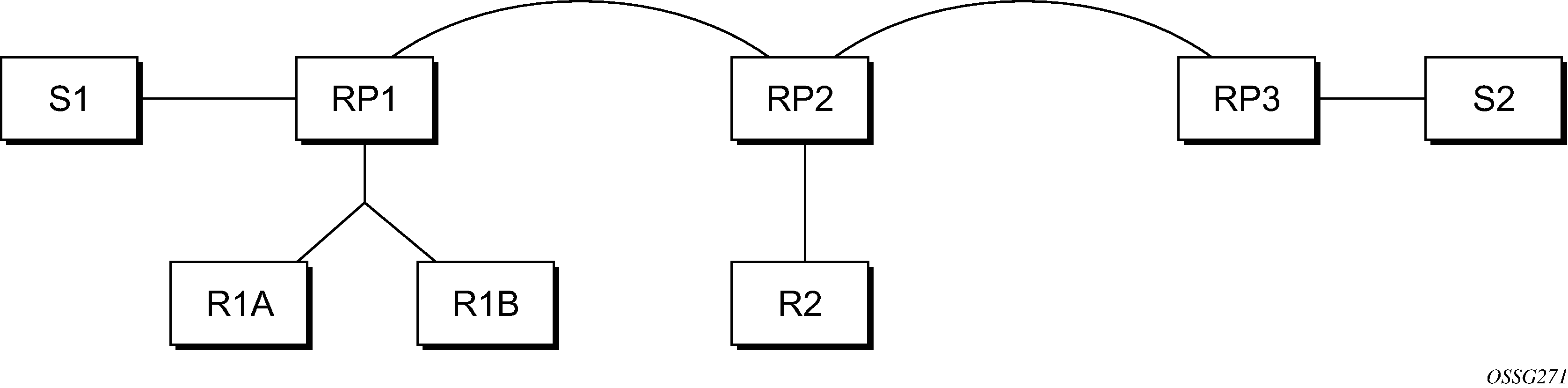
The following figure shows a scenario where all routers are connected, and where R1A, R1B, and R2 are receivers for a group, and S1 and S2 send to that group. Assume RP1, RP2, and RP3 are all assigned the same IP address that is used as the anycast-RP address (for example, the IP address is RPA).
The address used for the RP address in the domain (the anycast-RP address) must be different from the addresses used by the anycast-RP routers to communicate with each other.
The following procedure is used when S1 starts sourcing traffic:
S1 sends a multicast packet.
The DR directly attached to S1 forms a PIM register message to send to the anycast-RP address (RPA). The unicast routing system delivers the PIM register message to the nearest RP, in this case RP1.
RP1 receives the PIM register message, de-encapsulates it, and sends the packet down the shared tree to get the packet to receivers R1A and R1B.
RP1 is configured with RP2 and RP3 IP address. Because the register message did not come from one of the RPs in the anycast-RP set, RP1 assumes the packet came from a DR. If the register message is not addressed to the anycast-RP address, an error has occurred and it should be rate-limited logged.
RP1 sends a copy of the register message from S1 DR to both RP2 and RP3. RP1 uses its own IP address as the source address for the PIM register message.
RP1 may join back to the source tree by triggering a (S1,G) Join message toward S1; however, RP1 must create the (S1,G) state.
RP2 receives the register message from RP1, de-encapsulates it, and also sends the packet down the shared tree to get the packet to receiver R2.
RP2 sends a register-stop message back to the RP1. RP2 may wait to send the register-stop message if it decides to join the source tree. RP2 should wait until it has received data from the source on the source tree before sending the register-stop message. If RP2 decides to wait, the register-stop message is sent when the next register is received. If RP2 decides not to wait, the register-stop message is sent now.
RP2 may join back to the source tree by triggering a (S1,G) Join message toward S1; however, RP2 must create the (S1,G) state.
RP3 receives the register message from RP1 and de-encapsulates it, but, because no receivers are joined for the group, it can discard the packet.
RP3 sends a register-stop message back to RP1.
RP3 creates a (S1,G) state so that when a receiver joins after S1 starts sending, RP3 can join quickly to the source tree for S1.
RP1 processes the register-stop message from RP2 and RP3. RP1 may cache on a per-RP/per-(S,G) basis the receipt of register-stop messages from the RPs in the anycast-RP set. This option is performed to increase the reliability of register message delivery to each RP. When this option is used, subsequent register messages received by RP1 are sent only to the RPs in the anycast-RP set that have not previously sent register-stop messages for the (S,G) entry.
RP1 sends a register-stop message back to the DR the next time a register message is received from the DR and, if all RPs in the anycast-RP set have returned register-stop messages for a particular (S,G) route when RP1 caches on a per-RP/per-(S,G) basis the receipt of register-stop messages from the RPs in the anycast-RP set.
The procedure for S2 sending follows the same previous steps, but it is RP3 that sends a copy of the register originated by S2 DR to RP1 and RP2. This example shows how sources anywhere in the domain, associated with different RPs, can reach all receivers, also associated with different RPs, in the same domain.