9. Network Group Encryption
This chapter provides information to configure network group encryption (NGE).
Topics in this chapter include:
9.1. NGE Overview
The network group encryption (NGE) feature enables end-to-end encryption of MPLS services, Layer 3 user traffic, and IP/MPLS control traffic. NGE is an encryption method that uses a group-based keying security architecture, which removes the need to configure individual encryption tunnels to achieve network-wide encryption.
NGE relies on the NSP NFM-P to manage the network and apply encryption to specific MPLS services, Layer 3 user traffic, or control plane traffic depending on the security requirements of the network. Operators designate traffic types that require added security and then apply NGE to those traffic types using the NSP NFM-P. The NSP NFM-P also acts as the network-wide NGE key manager, downloading encryption and authentication keys to nodes and performing hitless rekeying of the network at operator-defined intervals. For more information about managing NGE within a network, see the NSP NFM-P User Guide.
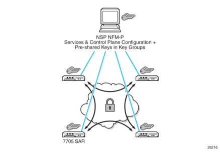
Figure 134 shows an NGE network with NSP NFM-P services, control plane configuration, and key management.
Figure 134: NGE Network with NSP NFM-P Management
NGE is enabled on the 7705 SAR and provides three main types of encryption to secure an IP/MPLS network:
- SDP encryption — MPLS user plane encryption enabled on MPLS tunnels (SDPs) supporting VPRN or IES services using spoke SDPs, VPLS using spoke or mesh SDPs, routed VPLS into VPRN, Epipes, and Cpipes
- VPRN encryption
- unicast VPRN — MP-BGP-based VPRN-level encryption using spoke SDPs (spoke-sdp) or auto-bind SDPs (auto-bind-tunnel) with LDP, GRE, RSVP-TE, or segment routing (SR-ISIS, SR-OSPF, or SR-TE) tunnels
- multicast VPRN — NG-MVPN using mLDP with auto-discovery
- router interface and Ethernet port Layer 2 encryption — Layer 3 user plane and control plane encryption, Layer 2 encryption of IS-IS and LLDP
NGE is supported on the following adapter cards and platforms:
- 8-port Gigabit Ethernet Adapter card, version 3
- 6-port Ethernet 10Gbps Adapter card
- 10-port 1GigE/1-port 10GigE X-Adapter card, version 2
- 7705 SAR-Ax
- 7705 SAR-H (Ethernet and PPP/MLPPP network links)
- 7705 SAR-Hc
- 7705 SAR-W
- 7705 SAR-Wx
- 7705 SAR-X (Ethernet and PPP/MLPPP network links)
This section contains information on the following topics:
9.1.1. NGE Key Groups and Encryption Partitions
The NGE feature allows a tiered approach to managing encryption keys in a network using key groups. This is accomplished by the configuration of services, router interfaces, or Ethernet ports to use specific key groups depending on security policies for the service and network topology.
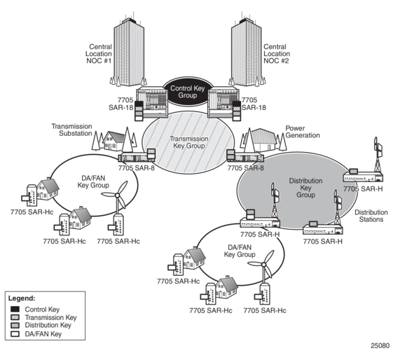
Figure 135 shows a typical application of NGE key-group partitioning in which there are several critical levels (tiers) of security that need to be considered. In this example, the protection of Distribution Automation and Field Area Network (DA/FAN) equipment might be considered less critical than the Transmission or Distribution Substation network equipment. It may be ideal to ensure that nodes more at risk of a security breach do not contain more critical information than is necessary. Therefore, encryption keys for the sensitive portions of the network (such as control center traffic) should not be available on nodes that are at risk. The 7705 SAR NGE feature enables operators to partition and distribute encryption keys among different services, NGE domains, or nodal groups in a network. NGE partitions are enabled by configuring different key groups per security partition and applying those key groups as needed.
Figure 135: Key-Group Partitioning
Another application of key-group partitioning allows different parts of an organization to have their own method of end-to-end communication without the need to share encryption keys between each organization. If two partitions need to communicate between themselves, gateway nodes configured with both key groups allow inter-organization traffic flows between the key group partitions, as needed.
9.1.2. NGE Domains
An NGE domain is a group of nodes and router interfaces forming a network that uses a single key group to create a security domain. NGE domains are created when router interface encryption is enabled on router interfaces that need to participate in the NGE domain. The NSP NFM-P assists operators in managing the nodes and interfaces that participate in the NGE domain. See the NSP NFM-P User Guide for more information.
Figure 136 shows various traffic types crossing an NGE domain.
Figure 136: NGE Domain Transit
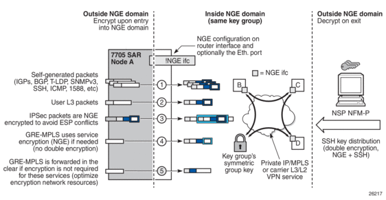
In the figure, nodes A, B, C, and D have router interfaces configured with router interface encryption enabled (and optionally Layer 2 NGE on the Ethernet port). Traffic is encrypted when entering the NGE domain using the key group configured on the router interface and is decrypted when exiting the NGE domain.
Traffic may traverse multiple hops before exiting the NGE domain, yet decryption only occurs on the final node when the traffic exits the NGE domain. Various traffic types are supported and encrypted when entering the NGE domain, as illustrated by the following items on node A in Figure 136:
- item 1: self-generated packets — these packets, which include all types of control plane and management packets such as OSPF, BGP, LDP, SNMPv3, SSH, ICMP, RSVP-TE, and 1588, are encrypted
- item 2: user Layer 3 packets — any Layer 3 user packets that are routed into the NGE domain from an interface outside the NGE domain are encrypted
- item 3: IPSec packets — IPSec packets are NGE-encrypted when entering the NGE domain to ensure that the IPSec packet’s security association information does not conflict with the NGE domain
GRE-MPLS-based service traffic consists of Layer 3 packets, and router interface NGE is not applied to these types of packets. Instead, service-level NGE is used for encryption to avoid double-encrypting these packets and impacting throughput and latencies. The two types of GRE-MPLS packets that can enter the NGE domain are illustrated by items 4 and 5 in Figure 136.
- item 4: GRE-MPLS packets (SDP or VPRN) with service-level NGE enabled — these encrypted packets use the key group that is configured on the service. The services key group may be different from the key group configured on the router interface where the GRE-MPLS packet enters the NGE domain.
- item 5: GRE-MPLS packets (SDP or VPRN) with NGE disabled — these packets are not encrypted and can traverse the NGE domain in clear text. If these packets require encryption, SDP or VPRN encryption must be enabled.
Creating an NGE domain from the NSP NFM-P requires the operator to determine the type of NGE domain being managed. This will indicate whether NGE gateway nodes are required to manage the NGE domain, and other operational considerations. The two types of NGE domains are:
9.1.2.1. Private IP/MPLS Network NGE Domain
One type of NGE domain is a private IP/MPLS network, as shown in Figure 137.
Figure 137: Private IP/MPLS Network NGE Domain
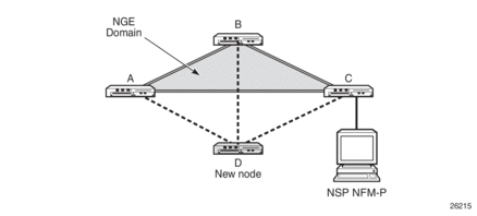
In a private IP/MPLS network NGE domain, all interfaces are owned by the operator and there is no intermediary service provider needed to interconnect nodes. Each interface is a point-to-point private link between private nodes. When a new node is added to this type of NGE domain (node D in Figure 137), the links that connect node D to the existing nodes in the NGE domain (nodes A, B, and C) must be enabled with NGE router interface encryption. Links from the new node to the existing nodes are enabled one at a time. The NSP NFM-P provides tools that simplify adding nodes to the NGE domain and enabling NGE on their associated interfaces. In this type of NGE domain, each interface is a direct link between two nodes and is not used to communicate with multiple nodes over a broadcast medium offered by an intermediary network. Also, there are no NGE gateway nodes required between the NSP NFM-P and new nodes entering the NGE domain.
9.1.2.2. Private Over Intermediary Network NGE Domain
The other type of NGE domain is a private IP/MPLS network that traverses an intermediary network NGE domain; the intermediary network is used to interconnect nodes in the NGE domain using a multipoint-to-multipoint service. The intermediary network is typically a service provider network that provides a private IP VPN service or a private VPLS service used to interconnect a private network that does not mimic point-to-point links as described in the Private IP/MPLS Network NGE Domain section.
This type of NGE domain is shown in Figure 138.
Figure 138: Private Over Intermediary Network NGE Domain
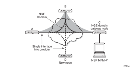
Private over intermediary network NGE domains have nodes with links that connect to a service provider network where a single link can communicate with multiple nodes over a Layer 3 service such as a VPRN or a Layer 2 service such as VPLS. In Figure 138, node A has NGE enabled on its interface with the service provider and uses that single interface to communicate with nodes B and C, and eventually with node D when node D has been added to the NGE domain. This type of NGE domain requires the recognition of NGE gateway nodes that allow the NSP NFM-P to reach new nodes that enter the domain. Node C is designated as a gateway node.
When node D is added to the NGE domain, it must first have the NGE domain key group downloaded to it from the NSP NFM-P. The NSP NFM-P creates an NGE exception ACL on the gateway node, C, to allow communication with node D using SNMPv3 and SSH through the NGE domain. After the key group is downloaded, the NSP NFM-P enables router interface encryption on node D’s interface with the service provider and node D is now able to participate in the NGE domain. The NSP NFM-P automatically removes the IP exception ACL from node C when node D enters the NGE domain.
See Router Interface NGE Domain Concepts for more information.
9.1.3. Network Services Platform Management
The NGE feature is tightly integrated with the NSP NFM-P. The following functions are provided by the NSP NFM-P :
- managing and synchronizing encryption and authentication keys within key groups on a network-wide basis
- configuring NGE on MPLS services and managing associated key groups
- configuring NGE on router interfaces and Ethernet ports and managing associated key groups
- coordinating network-wide rekeying of key groups
The NSP NFM-P acts as the key manager for NGE-enabled nodes and allocates the keys in key groups that are used to perform encryption and authentication. The NSP NFM-P ensures that all nodes in a key group are kept in synchronization and that only the key groups that are relevant to the associated nodes are downloaded with key information.
The NSP NFM-P performs network-wide hitless rekeying for each key group at the rekeying interval specified by the operator. Different key groups can be rekeyed at different times if desired, or all key groups can be rekeyed network-wide at the same time.
For more information on NSP NFM-P management, refer to the “Service Management” section in the NSP NFM-P User Guide.
9.2. Key Groups
Key groups are used to organize encryption keys into distinct groups that allow a user to partition the network based on security requirements. A key group contains the following elements:
- an encryption algorithm—see Key Group Algorithms
- an authentication algorithm—see Key Group Algorithms
- a list of security associations (SAs)—see Security Associations (SAs)
- an active outbound SA—see Active Outbound SA
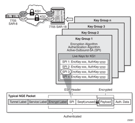
Figure 139 illustrates the use of key groups (KGs), security associations (SAs), and security parameter indexes (SPIs). The 7705 SAR-8 Shelf V2 and 7705 SAR-18 both have the same set of key groups configured. One path uses key group 1 (KG1) and the other uses key group 2 (KG2). Each key group contains the elements listed above. Key group 1 has four live keys, SPI_1 through SPI_4, and SPI_3 is the active outbound SA. The active outbound SA is identified by its SPI, and this SPI is embedded in the NGE packet.
Each SA listed in a key group, indexed by an SPI, specifies a single key for encryption and a single key for authentication. Packets transmitted or received that reference a particular SPI use the keys in the SA for that SPI when performing encryption and authentication.
Before enabling encryption, key groups must be configured on the node. Only after a key group is configured can it be assigned to an SDP or VPRN services.
Figure 139: Key Groups and a Typical NGE Packet
9.2.1. Key Group Algorithms
All SAs configured in a key group share the same encryption algorithm and the same authentication algorithm. The size and values required by a particular key depend on the requirements of the algorithms selected (see lists below). One encryption algorithm and one authentication algorithm must be selected per key group.
Encryption algorithms available per key group include:
- AES128 (a 128-bit key, requiring a 32-digit ASCII hexadecimal string)
- AES256 (a 256-bit key, requiring a 64-digit ASCII hexadecimal string)
Authentication algorithms available per key group include:
- HMAC-SHA-256 (a 256-bit key, requiring a 64-digit ASCII hexadecimal string)
- HMAC-SHA-512 (a 512-bit key, requiring a 128-digit ASCII hexadecimal string)
Encryption and authentication strengths can be mixed depending on the requirements of the application. For example, 256-bit strength encryption can be used with 512-bit strength authentication.
The configured algorithms cannot be changed when there is an existing SA configured for the key group. All SAs in a key group must be deleted before a key group algorithm can be modified.
Key values are not visible in CLI or retrievable using SNMP. Each node calculates a 32-bit CRC checksum for the keys configured against the SPI. The CRC can be displayed in the CLI or read by SNMP. The purpose of the CRC is to provide a tool to check consistency between nodes, thereby verifying that each node is set with the same key values while keeping the actual key values hidden.
9.2.1.1. Encapsulating Security Payload (ESP)
The NGE feature uses the Encapsulating Security Payload (ESP) protocol according to IETF RFC 4303. ESP maintains data integrity, ensuring privacy and confidentiality for encrypted traffic.
The ESP protocol used by NGE relies on symmetric ciphers, meaning that the same key is used for encryption and decryption. The 7705 SAR supports Cipher Block Chaining (CBC) encryption mode. Block ciphers used by NGE include:
- AES128 with a 128-bit key using 128-bit blocks
- AES256 with a 256-bit key using 128-bit blocks
For authentication, the integrity check value (ICV) size is as follows:
- HMAC-SHA-256 (16 bytes or 128 bits)
- HMAC-SHA-512 (32 bytes or 256 bits)
9.2.2. Security Associations (SAs)
Each key group has a list of up to four SAs. An SA is a reference to a pair of encryption and authentication keys that are used to decrypt and authenticate packets received by the node and to encrypt packets leaving the node.
For encrypted ingress traffic, any of the four SAs in the key group can be used for decryption if there is a match between the SPI in the traffic and the SPI in the SA. For egress traffic, only one of the SAs can be used for encryption and is designated as the active outbound SA. Figure 139 illustrates these relationships.
As shown in Figure 139, each SA is referenced by an SPI value, which is included in packets during encryption and authentication. SPI values must be numerically unique throughout all SAs in all key groups. If an SPI value is configured in one key group and an attempt is made to configure the same SPI value in another key group, the configuration is blocked.
| Note: Keys are entered in clear text using the security-association command. Once entered, they are never displayed in their original, clear text form. Keys are displayed in a 7705 SAR-encrypted form, which is indicated by the system-appended crypto keyword when an info command is run. The 7705 SAR also includes the crypto keyword with an admin>save operation so that the 7705 SAR can decrypt the keys when reloading a configuration database. For security reasons, keys encrypted on one node are not usable on other nodes (that is, keys are not exchangeable between nodes). |
9.2.2.1. Active Outbound SA
The active outbound SA is specified by the SPI referencing the specific SA used to encrypt and authenticate packets egressing the node for the SDP or service using the key group. The SPI value for the active outbound SA is included in the Encapsulating Security Payload (ESP) header of packets being encrypted and authenticated.
9.3. Services Encryption
The NGE feature provides the ability to encrypt MPLS services using key groups that are configured against these services. These services include:
- VLL service (Epipe and Cpipe)
- VPRN service using Layer 3 spoke-SDP termination
- IES service using Layer 3 spoke-SDP termination
- VPLS service using spoke and mesh SDPs
- routed VPLS service into a VPRN or IES
- MP-BGP-based VPRNs
- NG-MVPN
For services that use SDPs, all tunnels may be either MPLS LSPs (RSVP-TE, LDP, or static LSP) or GRE tunnels. NGE is not supported for IP tunnels.
For MP-BGP services, resolving routes using spoke SDPs (spoke-sdp) or auto-bind SDPs (auto-bind-tunnel) is supported using LDP, GRE, RSVP-TE, or segment routing (SR-ISIS, SR-OSPF, or SR-TE).
In addition, the 7705 SAR supports VLL, VPLS, and VPRN NGE interactions that use segment routing with entropy labels.
This section contains information on the following topics:
9.3.1. Services Encryption Overview
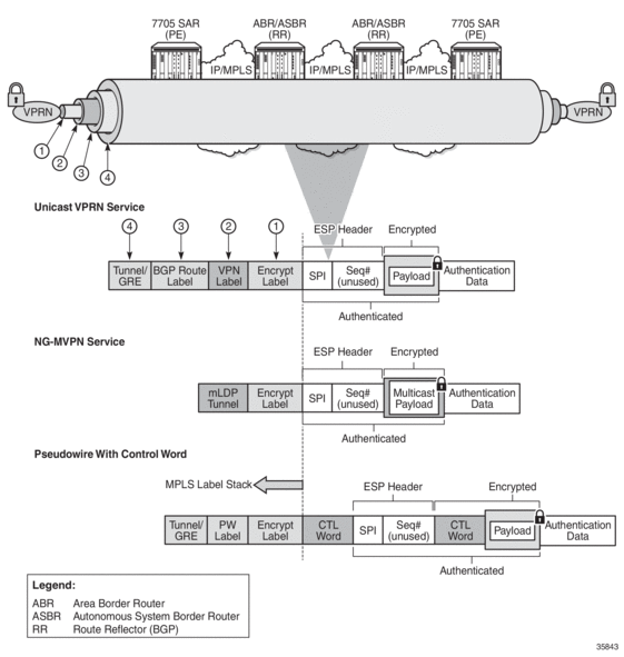
NGE adds a global encryption label to the label stack for encrypting MPLS services. The global encryption label must be a unique network-wide label; in other words, the same label must be used on all nodes in the network that require NGE services. The label must be configured on individual nodes before NGE can become operational on those nodes.
The global encryption label is used to identify packets that have an NGE-encrypted payload and is added to the bottom of the stack. This allows network elements such as LSRs, ABRs, ASBRs, and RRs to forward NGE packets without needing to understand NGE or to know that the contents of these MPLS packets are encrypted. Only when a destination PE (7705 SAR) receives a packet that needs to be understood at the service layer does the PE check for an encryption label, and then decrypt the packet.
Once the global encryption label is set, it should not be changed. If the label must be changed without impacting traffic, all key groups in the system should first be deleted. Next, the label should be changed, and then all key groups should be reconfigured.
The NSP NFM-P helps to coordinate the distribution of the global encryption label and ensures that all nodes in the network are using the same global encryption label.
Figure 140 illustrates the NGE MPLS/GRE label stack. Figure 141 illustrates VPRN and PW (with control word) packet formats using NGE encryption.
Figure 140: NGE MPLS/GRE Label Stack

Figure 141: NGE Encryption and Packet Formats
9.3.2. Assigning Key Groups to Services
Assigning key groups to services requires configuring an inbound and outbound key group for directional processing on a per-service basis (see Figure 142).
Figure 142: Inbound and Outbound Key-Group Assignments
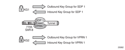
The outbound key group identifies which key group to use for traffic that egresses the node for the service. The inbound key group ensures that ingress traffic is using the correct key group for the service.
If the inbound key group is not set, the node ensures that packets are either unencrypted or are using one of the valid key groups configured in the system.
In most deployment scenarios, the inbound and outbound key groups are identical. However, it is possible to configure different key groups as the outbound and the inbound key groups, as this is not checked by the node. Using different key groups in this way is not typical.
Including an inbound and outbound direction when assigning key groups to services allows users to:
- gracefully enable and disable NGE for services
- move services from one key-group domain to another domain without halting encryption
The NGE feature makes use of the NSP NFM-P to help manage the assignment of key groups to services on a network-wide basis. Refer to the NSP NFM-P User Guide for more information.
9.3.3. Pseudowire Switching for NGE Traffic
For VLL services, the 7705 SAR supports pseudowire (PW) switching of encrypted traffic from one PW to another. There are three scenarios that are supported on the 7705 SAR with regard to PW switching of traffic:
- PW switch using the same key groupWhen a PW is using an encrypted SDP, the PW may be switched to another PW that is also using an encrypted SDP, and both SDPs are in the same key group. For this case, to perform the PW switch, the 7705 SAR leaves the encrypted payload unchanged and swaps the labels as needed for passing traffic between PWs.
- PW switch using different key groupsWhen a PW is using an encrypted SDP, the PW may be switched to another PW that is also using an encrypted SDP, but both SDPs are in different key groups. For this case, the 7705 SAR decrypts the traffic from the first SDP by using the configured key group for that SDP, and then re-encrypts the traffic by using the egress SDP's key group egress SPI ID.
- PW switch between an encrypted and unencrypted PWWhen traffic is switched from an encrypted PW to an unencrypted PW, the traffic is decrypted before it is sent. The converse occurs in the reverse direction (that is, traffic from an unencrypted PW to an encrypted PW gets encrypted before it is sent).
See Pseudowire Switching for more information.
9.3.4. Pseudowire Control Word for NGE Traffic
The control word is a configurable option for PWs and is included in PW packets when it (the control word) is configured. When control-word is enabled and NGE is used, the datapath creates two copies of the CW. One CW is both encrypted and authenticated, and is inserted after the ESP header. The other CW is not encrypted (clear form) and is inserted before the ESP header.
For cases where PW switching is configured, the 7705 SAR ensures—in the CLI and with SNMP—that both segments of the PW have consistent configuration of the control word when encryption is being used.
See Pseudowire Control Word for more information.
9.3.5. VPRN Layer 3 Spoke-SDP Encryption and MP-BGP-based VPRN Encryption Interaction
The encryption configured on an SDP used to terminate the Layer 3 spoke SDP of a VPRN always overrides any VPRN-level configuration for encryption:
- When VPRN encryption is enabled, all routes resolved via MP-BGP (either with spoke SDPs using spoke-sdp or auto-bind SDPs using auto-bind-tunnel) are encrypted or decrypted using the VPRN key group.
- When Layer 3 spoke-SDP encryption is enabled, all routes resolved via the Layer 3 interface are encrypted or decrypted using the SDP's key group.
Some examples are as follows.
- If a VPRN is enabled for encryption while a Layer 3 spoke SDP for the same VPRN is using an SDP that is not enabled for encryption, then traffic egressing the spoke SDP is not encrypted.
- If a VPRN is disabled for encryption while a Layer 3 spoke SDP for the same VPRN is using an SDP that is enabled for encryption, then traffic egressing the spoke SDP is encrypted.
- If a VPRN is enabled for encryption using key group X, while a Layer 3 spoke SDP for the same VPRN is using key group Y, then traffic egressing the spoke SDP is encrypted using key group Y.
The commands used for these scenarios are config>service>sdp>encryption-keygroup and config>service>vprn>encryption-keygroup.
9.3.6. NGE and RFC 3107
When RFC 3107 is enabled on the node and NGE traffic is crossing the RR between two VPRN domains, the same key group must be used between the two domains.
| Note: It is the responsibility of the network operator to ensure key group consistency across the RR. |
9.3.7. NGE for NG-MVPN
NGE is supported for NG-MVPN services with multicast configurations that include:
- I-PMSI
- S-PMSI
- C-multicast signaling
- mLDP multicast tunnel LSPs
For more information on MVPN, see Multicast VPN (MVPN).
When r-VPLS is configured for the VPRN, the node can act as a receiver for an NG-MVPN service that is NGE -encrypted. The node cannot act as a source of NG-MVPN traffic from a VPLS service, so the source of this NG-MVPN traffic must originate from another node that supports that capability.
When NGE is enabled in a VPRN with NG-MVPN-based services, transit nodes (LSRs) have no knowledge that NGE is being employed or that the NGE encryption label is being used with an ESP header after the NGE label. Features that inspect packet contents to make further decisions are not supported and must be disabled for mLDP multicast paths that need to carry NG-MVPN traffic that is NGE-encrypted. These features include:
- ingress multicast path management (7750 SR only)
- IP-based LSR hashing
The packet inspection restriction includes any third-party routing function that may inspect the packet contents after the mLDP transport label and is expecting a non-encrypted payload in order to make hashing decisions.
9.4. Router Interface Encryption
The 7705 SAR supports Layer 3 encryption on router interfaces for IPv4 traffic. NGE is not supported on dual-stack IPv4/IPv6 or IPv6-only interfaces.
NGE is enabled on a router interface by configuring the group-encryption command on the router interface. The interface is considered part of the NGE domain, and any received packets that are NGE-encrypted are decrypted if the key group is configured on the node. To encrypt packets egressing the interface, the outbound key group must be configured on the interface. All IP packets, such as self-generated traffic or packets forwarded from router interfaces that are not inside the NGE domain, are encrypted when egressing the interface. There are some exceptions to this general behavior, as described in the sections below; for example, GRE-MPLS packets are not encrypted when router interface encryption is enabled.
The outbound and inbound key groups configured on the router interface determine which keys to use to encrypt and decrypt traffic.
To perform encryption, router interface encryption reuses the IPSec transport mode packet format as shown in Figure 143.
Figure 143: Router Interface Encryption Packet Format (IPSec Transport Mode)

The protocol field in the IP header of an NGE packet is always set to “ESP”. Within an NGE domain, the SPI that is included in the ESP header is always an SPI for the key group configured on the router interface. Other fields in the IP header, such as the source and destination addresses, are not altered by NGE router interface encryption. Packets are routed through the NGE domain and decrypted when the packet leaves the NGE domain.
The group keys used on an NGE-enabled router interface provide encryption of broadcast and multicast packets within the GRT. For example, OSPF uses a broadcast address to establish adjacencies, which can be encrypted by NGE without the need to establish point-to-point encryption tunnels. Similarly, multicast packets are also encrypted without point-to-point encryption tunnels.
9.4.1. Router Interface NGE Domain Concepts
An NGE domain is a group of nodes whose router interfaces in the base routing context (GRT) are enabled for router interface NGE or whose ports are enabled for encryption of some types of Layer 2 traffic. An interface without router interface NGE enabled is considered to be outside the NGE domain. NGE domains use only one key group when the domain is created; however, two key groups may be active at once if some links within the NGE domain are in transition from one key group to the other.
Figure 144 illustrates the NGE domain concept. Table 189 describes the three configuration scenarios inside the NGE domain.
Figure 144: Inside and Outside NGE Domains
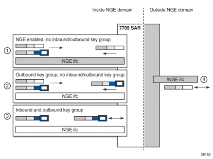
Table 189: Inside and Outside NGE Domains — Configuration Scenarios
Key | Description |
1 | NGE enabled, no inbound/outbound key group Outbound packets are sent without encrypting. Inbound packets can be NGE-encrypted or clear text. |
2 | Outbound key group, no inbound key group Outbound packets are encrypted using the interface key group if not already encrypted. Inbound packets can be NGE-encrypted or clear text. |
3 | Inbound and outbound key group Outbound packets are encrypted using the interface key group if not already encrypted. Inbound packets must be encrypted using the interface key group keys. |
4 | Outside the NGE domain, the interface is not configured for NGE. Any ESP packets are IPSec packets. |
A router interface is considered to be inside the NGE domain when it has been configured with group-encryption on the interface. When group-encryption is configured on the interface, the router can receive unencrypted packets or NGE-encrypted packets from any configured key group on the router, but any other type of IPSec-formatted packet is not allowed. If an IPSec-formatted packet is received on an interface that has group-encryption enabled, it will not pass NGE authentication and will be dropped. Therefore, IPSec packets cannot exist within the NGE domain without first being converted to NGE packets. This conversion requirement delineates the boundary of the NGE domain and other IPSec services.
When NGE router interface encryption is enabled and only an outbound key group is configured, the interface can receive unencrypted packets or NGE-encrypted packets from any configured key group on the router. All outbound packets are encrypted using the outbound key group if the packet was not already encrypted further upstream in the network.
When NGE router interface encryption has been configured with both an inbound and outbound key group, only NGE packets encrypted with the key group security association can be sent and received over the interface.
When there is no NGE router interface encryption, the interface is considered outside the NGE domain where NGE is not applied.
9.4.2. GRE-MPLS Packets Inside the NGE Domain
NGE router interface encryption is never applied to GRE-MPLS packets that are used to transport MPLS services over Layer 3 networks; for example, GRE with the GRE protocol ID set to MPLS Unicast (0x8847) or Multicast (0x8848). GRE-MPLS packets that enter the NGE domain or transit the NGE domain are forwarded as is.
Because GRE-MPLS packets provide transport for MPLS-based services, they already use the NGE services-based encryption techniques for MPLS, such as SDP or VPRN-based encryption. To avoid double encryption, the packets are left in clear text when entering an NGE domain or crossing intermediate nodes in the NGE domain, and are simply forwarded as needed when exiting an NGE domain.
The payload of these GRE-MPLS packets can also be sent in clear text depending on the security requirements that are configured for the MPLS service.
GRE packets with the protocol set to other protocols are encrypted using NGE router interface encryption.
9.4.3. Router Encryption Exceptions using ACLs
In some cases, Layer 3 packets may need to cross the NGE domain in clear text, such as when an NGE-enabled router needs to peer with a non-NGE-capable router to exchange routing information. This can be accomplished by using a router interface NGE exception filter applied on the router interface for the required direction, inbound or outbound.
Figure 145 shows the use of a router interface NGE exception filter.
Figure 145: Router Interface NGE Exception Filter Example
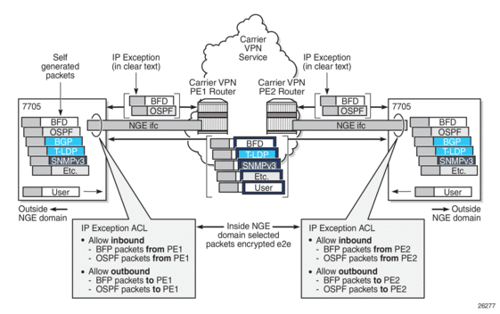
The inbound or outbound exception filter is used to allow specific packet flows through the NGE domain in clear text, where there is an explicit inbound and outbound key group configured on the interface. The behavior of the exception filter for each router interface configuration is as follows:
- NGE enabled, no inbound/outbound key group — in this scenario, the router does not encrypt outbound traffic, and so the outbound exception filter is not applied. The router can still receive inbound NGE packets, so the exception filter is applied to inbound packets. If the filter detects a match, clear text packets can be received and forwarded by the router.
- outbound key group, no inbound key group — the outbound exception filter is applied to outbound traffic, and packets that match the filter are not encrypted on egress. The router can receive inbound NGE packets without an inbound key group set and applies the exception filter to inbound packets. If the filter detects a match, clear text packets can be received and forwarded by the router.
- inbound and outbound key group — the inbound and outbound exception filters are applied, and any packets that match are passed in clear text.
9.4.4. IPSec Packets Crossing an NGE Domain
IPSec packets can cross the NGE domain because they are still considered Layer 3 packets. To avoid confusion between the security association used in an IPSec packet and the one used in a router interface NGE packet, the router will always apply NGE to any IPSec packet that traverses the NGE domain.
IPSec packets that originate from a router within the NGE domain are not allowed to enter the NGE domain. The only exception to this restriction is OSPFv3 packets.
Figure 146 shows how IPSec packets can transit an NGE domain.
Figure 146: IPSec Packets Transiting an NGE Domain
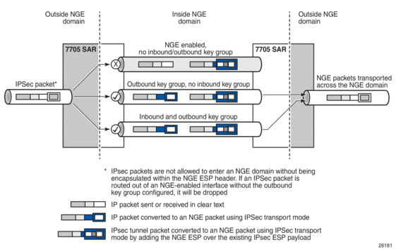
An IPSec packet enters the router from outside the NGE domain. When the router determines that the egress interface to route the packet is inside an NGE domain, it will select an NGE router interface with one of the following configurations.
- NGE enabled with no inbound or outbound key group configured — this link cannot forward the IPSec packet without adding the NGE ESP, but since nothing is configured for the outbound key group, the packet must be dropped.
- NGE enabled with outbound key group configured and no inbound key group configured — the packet originates outside the NGE domain, so the router adds an ESP header over the existing ESP and encrypts the payload using the NGE domain keys for the configured outbound key group.
- NGE enabled with both inbound and outbound key groups configured — the packet originates outside the NGE domain, so the router adds an ESP header over the existing ESP and encrypts the payload using the NGE domain keys for the configured outbound key group.
OSPFv3 IPSec support also uses IPSec transport mode packets. These packets originate from the CSM, which is considered outside the NGE domain; however, the above rules for encapsulating the packets with an NGE ESP apply and allow these packets to successfully transit the NGE domain.
9.4.5. Multicast Packets Traversing the NGE Domain
Multicast packets that traverse an NGE domain can be categorized into two main scenarios:
- Scenario 1 — multicast packets that ingress the router on an interface that is outside the NGE domain. These packets can egress a variety of interfaces that are either inside or outside the NGE domain.
- Scenario 2 — multicast packets that ingress the router on an interface that is inside the NGE domain. These packets can egress a variety of interfaces that are either inside or outside the NGE domain. This scenario has two cases:
- Scenario 2a — the ingress multicast packet is not yet NGE-encrypted
- Scenario 2b — the ingress multicast packet is NGE-encrypted
Figure 147 shows these scenarios.
Figure 147: Processing Multicast Packets
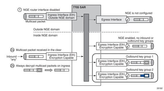
Multicast packets received from outside the NGE domain (Scenario 1) are processed similarly to multicast packets received from inside the NGE domain (Scenarios 2a and 2b).
The processing rule is that multicast packets are always forwarded as clear text over the fabric. This means that for Scenario 2b, when a multicast packet is received on an encryption-capable interface and is NGE-encrypted, the packet is always decrypted first so that it can be processed in the same way as packets in Scenarios 1 and 2a.
On egress, the following scenarios apply:
- egressing an interface outside the NGE domain — packets are processed in the same way as any multicast packets forwarded out a non-NGE interface
- egressing an NGE router interface and no inbound or outbound key group is configured — the router forwards these packets out from the egress interface without encrypting them since there is no outbound key group configured. This behavior also applies to unicast packets in the same scenario.
- egressing an NGE router interface with the outbound key group configured — the router encrypts the multicast packet using the SPI keys of the outgoing SA configured in the key group. This behavior also applies to unicast packets in the same scenario.
9.4.6. Assigning Key Groups to Router Interfaces
Assigning key groups to router interfaces involves the following three steps:
- Enable NGE with the group-encryption command.
- Configure the outbound key group.
- Configure the inbound key group.
Step 1 is required so that the router can initialize and differentiate the interface for NGE traffic before accepting or sending NGE packets. This assigns the interface to an NGE domain, and IPSec packets will no longer be accepted on the interface.
Assigning key groups to a router interface in steps 2 and 3 is similar to assigning key groups to SDPs or VPRN-based services. An outbound key group cannot be configured for a router interface without first enabling group-encryption.
When group-encryption is enabled and no inbound key group is configured, the router will accept NGE Layer 3 packets that were encrypted using keys from any security association configured in any key group on the system. If the packet specifies a security association that is not configured in any key group on the node, the packet is dropped.
The outbound key group references the key group to use when traffic egresses the router on the router interface. The inbound key group is used to make sure ingress traffic is using the correct key group on the router interface. If ingress traffic is not using the correct key group, the router counts these packets as errors.
9.4.7. Router Interface NGE Firewall Considerations
An interface that has been configured to exist inside the NGE domain cannot be added to a security zone; firewalls are not supported on NGE router interfaces, as shown in Figure 148.
Figure 148: Firewall Considerations
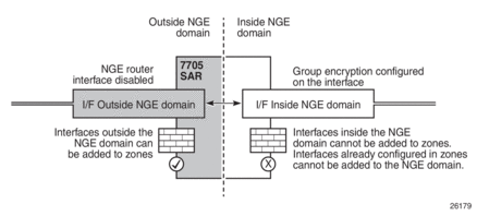
It is recommended that firewall security policies be enabled on interfaces outside the NGE domain before traffic is allowed to enter the NGE domain.
9.4.8. NGE and BFD Support
When NGE is enabled on a router interface, BFD packets that originate from the network processor on the adapter card or from the system are encrypted in the same way as BFD packets that are generated by the CSM.
9.4.9. NGE and ACL Interactions
When NGE is enabled on a router interface, the ACL function is applied as follows:
- on ingress — Normal ACLs are applied to traffic received on the interface that could be either NGE-encrypted or clear text. For NGE-encrypted packets, this implies that only the source, destination, and IP options are available to filter on ingress, as the protocol is ESP and the packet is encrypted. If an IP exception ACL is also configured on the interface, the IP exception ACL is applied first to allow any clear text packets to ingress as needed. After the IP exception ACL is applied and if another filter or ACL is configured on the interface, the other filter will process the remaining packet stream (NGE-encrypted and IP exception ACL packets), and other ACL functions such as PBR or Layer 4 information filtering could be applied to any clear text packets that passed the exception ACL.
- on egress — ACLs are applied to packets before they are NGE-encrypted as per normal operation without NGE enabled.
9.4.10. Router Interface NGE and ICMP Interactions Over the NGE Domain
Typically, ICMP works as expected over an NGE domain when all routers participating in the NGE domain are NGE-capable; this includes running an NGE domain over a private IP/MPLS network and over a Layer 2 service provider where dedicated point-to-point circuits are used to create single-hop links between NGE nodes. When an ICMP message is required, the NGE packet is decrypted first and the original packet is restored to create a detailed ICMP message using the original packet’s header information.
When the NGE domain crosses a Layer 3 service provider, or crosses over routers that are not NGE-aware, it is not possible to create a detailed ICMP message using the original packet’s information, as the NGE packet protocol is always set to ESP. Furthermore, the NGE router that receives these ICMP messages will drop them because the messages are not NGE-encrypted.
The combination of dropping ICMP messages at the NGE border node and the missing unencrypted packet details in the ICMP information can cause problems with diagnosing network issues.
To help with diagnosing network issues, additional statistics are available on the interface to show whether ICMP messages are being returned from a foreign node. The following statistics are included in the group encryption NGE statistics for an interface:
- Group Enc Rx ICMP DestUnRch Pkts
- Group Enc Rx ICMP TimeExc Pkts
- Group Enc Rx ICMP Other Pkts
These statistics are used when clear text ICMP messages are received on an NGE router interface. The Invalid ESP statistics are not used in this situation even though the packet does not have a correct NGE ESP header. If there is no ingress exception ACL configured on the interface to allow the ICMP messages to be forwarded, the messages are counted and dropped.
If more information is required for these ICMP messages, such as source or destination address information, a second ICMP filter can be configured on the interface to allow logging of the ICMP messages. If the original packet information is also required, an egress exception ACL can be configured with the respective source or destination address information, or other criteria, to allow the original packet to enter the NGE domain in clear text and determine which flows are causing the ICMP failures.
9.4.11. OAM Considerations for Router Interface Encryption
CSM timestamping is supported when NGE router interface encryption is enabled.
9.5. Layer 2 Encryption
Layer 2 encryption allows IS-IS and LLDP Layer 2 protocols to be encrypted using NGE key groups. Figure 149 shows the packet format for Layer 2 encryption.
Figure 149: Encrypted Layer 2 Packet
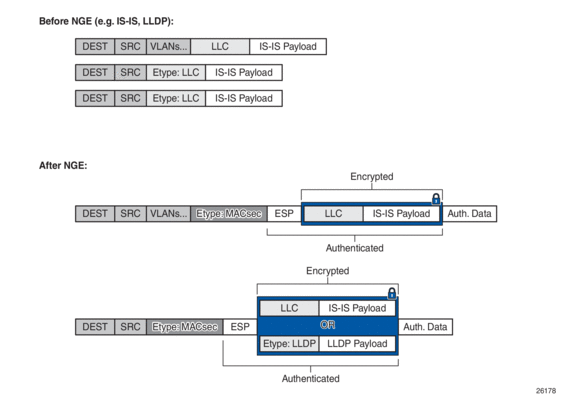
Similar to router interface encryption, which reuses IPSec transport mode formatted packets, Layer 2 NGE encryption reuses the MACsec Ethertype and the ESP protocol, as defined in RFC 4303, to encrypt the payload of a Layer 2 packet.
Layer 2 NGE is configured on network Ethernet ports; access ports and hybrid ports do not support Layer 2 encryption. When Layer 2 encryption is configured, all IS-IS and LLDP packets are encrypted using NGE. Layer 2 encryption does not encrypt any Layer 3 packets using NGE router interface encryption or MPLS packets using MPLS service encryption.
Layer 2 NGE encryption is enabled by configuring an outbound key group and an inbound key group on the Ethernet port and is similar to assigning key groups for router interface encryption as described in Assigning Key Groups to Router Interfaces. For example, to configure Layer 2 encryption on port 1/1/1:
config port 1/1/1 ethernet group-encryption encryption-keygroup 1 direction outbound
config port 1/1/1 ethernet group-encryption encryption-keygroup 1 direction inbound
The group-encryption command initializes the port for NGE Layer 2 encryption where both encrypted NGE Layer 2 packets and clear text packets can be received. The group-encryption command is used to add the port to an NGE domain and ensures that any received packets with the MACsec Ethertype are decrypted using NGE Layer 2 encryption.
The outbound key group references the key group to use for encrypting the supported Layer 2 packets egressing the router on the Ethernet port. The inbound key group is used to ensure that ingress traffic is using the correct key group. If ingress traffic that is not using the correct key group is detected, the packets are counted as errors.
If Layer 2 NGE is used for a LAG, each Ethernet port member of the LAG group must be configured with NGE. There is no NGE configuration inheritance from the primary port of a LAG group to its member ports. Each port operates based on its own NGE configuration.
For configuration guidelines for inbound and outbound key groups, see Configuration Notes.
9.6. NGE Packet Overhead and MTU Considerations
NGE adds overhead packets to services. Table 190 shows the additional overhead for the worst-case scenario of MPLS services encryption. Table 191 shows the additional overhead for the worst-case scenario of router interface and Layer 2 encryption. Additional overhead depends on which encryption and authentication algorithms are chosen.
Table 190: NGE Overhead for MPLS
Item | Number of Bytes |
Encryption label | 4 |
ESP | 24 |
ICV | 32 |
Padding | 17 |
Control word copy | 4 |
Total | 81 |
For MP-BGP-based VPRNs, the total is 77 bytes because the control word copy is not required.
Table 191: NGE Overhead for Router Interface and Ethernet Port NGE
Item | Number of Bytes |
ESP | 24 |
ICV | 32 |
Padding | 17 |
Total | 73 |
For Layer 3 packets for router interface encryption, and Layer 2 packets for Layer 2 encryption, the total is 73 bytes because the encryption label and control word copy are not required.
The overhead values in Table 190 must be considered for services that are supported by NGE.
| Note: Currently, the port MTU has a default value of 1572 bytes. This value is too low for outbound traffic when NGE is enabled. Users must configure new MTU values to adjust for the overhead associated with NGE, as outlined in Table 192 for MPLS-based and GRE-based services. For details on configuring MTU, refer to the “MTU Configuration Guidelines” section in the 7705 SAR Interface Configuration Guide. |
The calculations in Table 192 show how NGE overhead affects SDP MTU and service MTU values for MPLS-based, GRE-based, and VPRN-based services. The calculations are with and without NGE enabled.
Table 192: Accounting for NGE Overhead SDP and Service MTU — Calculation Examples
Service Type | MTU Values With and Without NGE Enabled | |
MPLS-based services | SDP MTU (MPLS) = 1572 (network port MTU) – 14 (Ethernet header) – 4 (outer label) – 4 (inner label) = 1550 bytes (without NGE enabled) => 1469 bytes (with NGE enabled) | |
Service MTU (MPLS) considerations with NGE enabled
| ||
GRE-based services | SDP MTU (GRE) = 1572 (network port MTU) – 14 (Ethernet header) – 20 (IP header) – 4 (GRE header) – 4 (inner label) = 1530 bytes (without NGE enabled) => 1449 bytes (with NGE enabled) | |
Service MTU (GRE) considerations with NGE enabled
| ||
VPRN-based services | Each interface inherits its MTU from the SAP or spoke SDP to which it is bound and the MTU value can be manually changed using the ip-mtu command. | |
MP-BGP-based VPRN services The MTU of the egress IP interface is used. When NGE is enabled on a VPRN service, customers must account for the additional 77 bytes of overhead needed by NGE for any egress IP interface used by the VPRN service. | ||
When an unencrypted Layer 3 packet ingresses the node and routing determines that the egress interface is a router interface NGE-enabled interface, the node calculates whether the packet size will be greater than the MTU of the egress interface after the router interface NGE overhead is added. If the packet cannot be forwarded out from the network interface, an ICMP message is sent back to the sender and the packet is dropped. Users must configure new MTU values to adjust for the overhead associated with NGE.
If an IP exception ACL that matches the ingressing packet exists on the egress interface, the MTU check applied to the ingress packet includes the router interface NGE overhead. This is because the ingress interface cannot determine which IP exceptions are configured on the egress interface, and therefore the worst-case MTU check that includes the router interface NGE overhead is performed.
9.6.1. GRE Fragmentation for NGE Packets
GRE fragmentation is supported on NGE-encrypted GRE SDP packets on the Ethernet interfaces of the adapter cards and platforms listed in NGE Overview.
To determine if an encrypted packet needs to be fragmented, the system compares the total packet size after NGE encryption to the network port MTU. If the encrypted packet size is larger than the MTU, the packet is fragmented. NGE decryption is performed after the packet is fully reassembled.
See GRE Fragmentation for more information.
9.7. 1588v2 Encryption With NGE
If a router interface is enabled for encryption and Layer 3 1588v2 packets are sent, they will be encrypted using NGE. This means that if port timestamping is enabled on a router interface with NGE, the port timestamp is applied to the Layer 3 1588v2 packet via software-based timestamping instead of hardware-based timestamping, and consequently timing accuracy may degrade. The exact level of timing or synchronization degradation is dependent on many factors, and testing is recommended to measure any impact.
If there is a need to support Layer 3 1588v2 with better accuracy for frequency or better time using port timestamping, an NGE exception ACL is required to keep the Layer 3 1588v2 packets in clear text. The exception ACL must enable UDP packets with destination port 319 to be sent in clear text.
Layer 2 1588v2 packets are always sent and received in clear text. When NGE is enabled on a Layer 2 port, encryption is not applied and existing Layer 2 1588v2 functions are not impacted.
9.8. QoS for NGE Traffic
The 7705 SAR provides priority and scheduling for traffic into the encryption and decryption engines on nodes that support NGE. This is described for the following traffic directions:
For information on QoS and QoS policies, refer to the 7705 SAR Quality of Service Guide. Also, since QoS for NGE is similar to QoS for IPSec, see QoS for IPSec for more information.
9.8.1. Network Ingress
NGE traffic arriving on network ingress is classified based on the network QoS policy that is assigned to the network router interface. This classification is done using the EXP bits of the outer MPLS tunnel LSP or the DSCP markings on the IP packet of GRE packets.
There are two queues provided for mapping ingress NGE traffic into the decryption engine—an expedited queue and a best-effort queue. The encrypted traffic maps to one of these queues based on the queue-type configuration of the network ingress queue and the FC-to-queue (classification) mapping. Specifically, at network ingress, the following occurs (as shown in Figure 150):
- the network QoS policy determines the forwarding class (FC) for the packet (item 1)
- the ingress network queue QoS policy maps the FC to a queue, where the queue-type has been configured as expedited, best-effort, or auto-expedite (item 2)
- the queue-type is used again to map to the appropriate queue into the decryption engine (that is, the expedited and best-effort queue) (item 3)
- after decryption, normal QoS processing takes place as if NGE was not enabled for the service (item 4)
Figure 150: QoS for NGE Traffic (Network Ingress)

For more information on QoS for network ingress, refer to the “Network Ingress” section in the 7705 SAR Quality of Service Guide.
9.8.2. Network Egress
Traffic egressing a network interface typically has a known FC based on the traffic management (TM) configuration at SAP ingress.
There are two queues provided for mapping egress NGE traffic into the encryption engine—an expedited queue and a best-effort queue. The traffic maps to one of these queues based on the FC of the packet, as determined at SAP ingress. Specifically, the following occurs:
- the SAP ingress QoS policy maps the FC to a queue-type, where the queue-type of the SAP-ingress queue has been configured as expedited, best-effort, or auto-expedite
- on the network egress side of the fabric, the ingress queue-type is used to map to the appropriate queue into the encryption engine (that is, the expedited and best-effort queue)
For more information on QoS for network egress, refer to the “Network Egress” section in the 7705 SAR Quality of Service Guide.
9.9. Statistics
Statistics specific to NGE are counted for the following main areas:
- key group
- SPI
- MDA
- service
9.10. Remote Network Monitoring (RMON) Support
Remote network Monitoring (RMON) can be used in conjunction with NGE statistics to provide event and alarm reporting. This can be used by customers to detect security breaches of NGE traffic flows and provide real-time reporting of such events.
Threshold crossing alerts and alarms using RMON are supported for SNMP MIB objects, including NGE.
9.11. Configuration Notes
This section describes NGE configuration guidelines and caveats. For more information about configuring NGE using the NSP NFM-P, see the NSP NFM-P User Guide.
To enable NGE for an SDP or VPRN service:
- Install the outbound direction key group on each node for the service.
- Install the inbound direction key group on each node for the service.
To enable NGE for a router interface:
- Enable group-encryption on the interface.
- Configure the outbound key group.
- Configure the inbound key group.
To change NGE from one key group to another key group for an SDP or VPRN service:
- Remove the inbound direction key group from each node for the service.
- Change the outbound direction key group on each node for the service.
- Install the new inbound direction key group on each node for the service.
To change NGE from one key group to another key group for a router interface:
- Remove the inbound key group.
- Configure the new outbound key group.
- Configure the new inbound key group.
To disable NGE for an SDP or VPRN service:
- Remove the inbound direction key group from each node providing the service.
- Remove the outbound direction key group from each node for the service.
To disable NGE for a router interface:
- Remove the inbound key group.
- Remove the outbound key group.
- Disable group-encryption on the interface.
Caveats:
- The authentication and encapsulation keys must contain the exact number of hexadecimal characters required by the algorithm used. For example, using sha256 requires 64 hexadecimal characters.
- The key group bound to an SDP or service must be unbound from that SDP or service before the active outgoing SA for the key group can be removed.
- The active outgoing SA must be removed (deconfigured) before the SPI can be deleted from the SA list in the key group.
- The encryption or authentication algorithm for a key group cannot be changed if there are any SAs in the key group.
- The encryption configured on an SDP used to terminate the Layer 3 spoke SDP of a VPRN (enabled or disabled) always overrides any VPRN-level configuration for encryption. See VPRN Layer 3 Spoke-SDP Encryption and MP-BGP-based VPRN Encryption Interaction for more information.
- The NSP NFM-P provides configuration parameters that are not configurable using the CLI. See Network Services Platform Management for more information.
9.11.1. Reference Sources
For information on supported IETF drafts and standards as well as standard and proprietary MIBS, refer to Standards and Protocol Support.