Last Updated:
2012-08-24 Version 1.0 MW-LINK Configuration Notes 7705 SAR R5.0 Configuration Note


Introduction:
The A8-PMC MDA is designed to interconnect with 9500 MPR-e radio units and provide a cost efficient method of back-hauling data without having physical fiber present between two sites that are geographically separated.
Microwave transport provides the following advantages:
- Rights of way and installation of fiber over large distances are replaced by obtainment of license for microwave channel from regulatory authority, and installation of radio tower.
- Equipment fully maintained and managed by provider as opposed to dark fiber, or leased line arrangements.
- Low cost.
This configuration note will detail the setup of two SAR’s interconnected via 9500 MPR-e’s.
Setup:
In this configuration, two 7705 SAR-8’s will be interconnected via a 9500 MPR-e radio link to support the back-haul of data.
Figure 1 – Equipment Overview
Each 7705 SAR-8 shelf contains a CSM module, a A8-PMC MDA in slot 4, and a MW-PIC-2 MDA in slot 5.
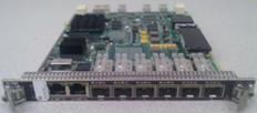
Figure 2 – A8-PMC MDA

Figure 3 – MW-PIC-2 MDA
The configuration of each SAR shelf is nearly identical, other than IP addresses, therefore the configuration steps for the first SAR and MPR-e will be detailed. Following, only the sync reference configuration for the remote SAR will be detailed.
Prerequisites:
- Powered SAR shelf with MDA’s installed.
- Mounted MPR-e unit plugged in to DATA+POWER port of MW-PIC-2 MDA via proper CAT5e cable.
- CAT5e cable connected between port 1 of A8-PMC MDA and DATA port of MW-PIC-2 MDA.
- Copper SFP plugged into port 8 of A8-PMC MDA.
- Computer with appropriate WebEML MPR TCO suite version.
o This computer will be plugged in to copper SFP on A8-PMC MDA.
o This computer will have a Serial cable to SAR CSM console interface.
Configuration:
The first step is to configure the QOS fabric policy:
*A:SAR8-1# configure qos
*A:SAR8-1>config>qos# info
----------------------------------------------
#--------------------------------------------------
echo "QoS Policy Configuration"
#--------------------------------------------------
fabric-profile 80
aggregate-mode create
description
“Profile for A8-PMC modules, up to 2.5Gbs if CSM can support”
aggregate-rate 1000000
exit
----------------------------------------------
The next step is to configure the MDA’s:
*A:SAR8-1>config>qos# \configure card 1
*A:SAR8-1>config>card# info
----------------------------------------------
card-type iom-sar
mda 5
mda-type a8-pmc
network
ingress
fabric-policy 80
exit
exit
exit
mda 6
mda-type mw-pic-2
exit
----------------------------------------------
Note: If the MPR-e is already configured for the management network, skip forward to the preparing port for the mw-link association.
After MDA configuration, we prepare the ports for MPR-e initial configuration if need be. These steps are useful if the computer is not able to support VLAN tags. If the MPR-e network configuration is already complete, we could skip forward to the mw-link creation section. Otherwise, we create an e-pipe service to perform the VLAN tagging for initial MPR-e setup:
*A:SAR8-1>config>card# \configure port 1/5/1
*A:SAR8-1>config>port# info
----------------------------------------------
ethernet
encap-type dot1q
exit
no shutdown
----------------------------------------------
*A:SAR8-1>confg>port# \configure port
1/5/8
*A:SAR8-1>confg>port# info
----------------------------------------------
ethernet
exit
no shutdown
----------------------------------------------
Now that the ports have been setup, we create a service to provide VLAN tagging in the default management VLAN of the MPR-e:
*A:SAR8-1>confg>port# \configure service
*A:SAR8-1>confg>service# epipe 80 customer 1 create
*A:SAR8-1>config>service>epipe# info
----------------------------------------------
description "Temporary e-pipe for initial MPR-e configuration"
sap 1/5/1:4080 create
exit
sap 1/5/8 create
exit
no shutdown
----------------------------------------------
Now we configure the computer network settings to be in the default TMN In-Band LAN subnet of the MPR-e:

Note: The default configuration of the MPR-e is to have different assigned IP addresses for the Management Network Element Address and the TMN In-Band Address making the management function a layer 3 router in the MPR-e. This is the reason for setting the default TMN In-Band Address as the Default gateway for the PC, so that the PC will know where to route packets destined for the Network Element Address.
Next we start the WebEML application and enter the default NE IP address (10.0.1.2) for the MPR-e, click OK, and then click Show:
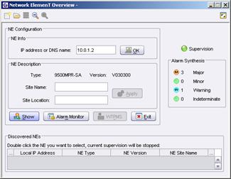
Note: The RF configuration of the MPR-e is beyond the scope of this document. The steps included in this configuration note are intended to cover SAR facing features only. The screens captured below may not be up to date and were taken with 9500 MPR-e 3.3 software. Please refer to up to date User Manuals for both the SAR and MPR information.
Next, we configure the synchronization parameters on the MPR-e:

The PCR Source and Destination MAC Addresses configured in the MPR-e is dependent on slot and port of connection to SAR. Since this MPR-e is to be connected to SAR port 1/5/1, we use the following Source and destination MAC addresses:
Source MAC address 00:80:9F:09:F5:15
Destination MAC address 00:80:9F:09:F5:05
The formula for the MAC addresses to be configured in the MPR-e is
00:80:9F:09:FS:PS
Where S = hexadecimal value for the slot of connection to SAR
Where P = 0 for the PCR Destination MAC Address
Where P = 1..4 for the PCR Source MAC Address based on SAR port
Note: PCR MAC Address configuration is only required in the MPR-e to match the automatic assignment in the SAR shelf by slot and port of the MDA and port connection to the MPR-e.
PCR is only to be selected and configured if the physical media of the data link is copper twisted pair (1000Base-T). For fiber connected radios (1000Base-X), SyncE should be selected in the MPR-e configuration. This selection is automatic within the SAR based on media type of the ethernet link.
Finally, we configure the management network settings for the MPR-e:

In this network, both the IP Address of the Network Element and the TMN In-Band interfaces will be the same. The change takes immediate effect after clicking apply, so only the Network Element interface will be changed initially. Then the management session will need to be restarted to the new target address. Afterwards, the IP Address, Subnet Mask, and VLAN ID of the TMN In-Band interface will be changed. After the TMN In-Band interface changes are applied, the computer IP settings will need to be modified in order to resume communications with the MPR-e.
Note: The default VLAN ID of the TMN In-Band interface is appropriate for the vast majority of applications.
The last required management network setting is to add the default route pointing to the interface address of the local SAR in the MPR-e.
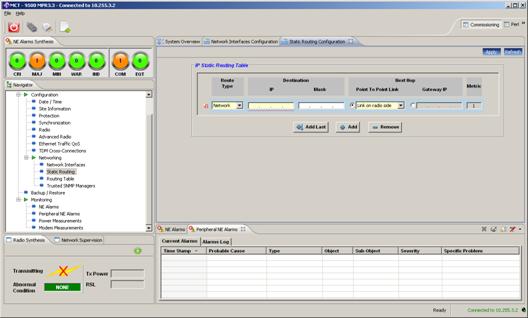
The Route Type of Default is selected, and the radio button for Gateway IP is also selected, placing the SAR interface address into the entry box and clicking + Add.
This completes the management network configuration of the MPR-e. This is also a convenient time to configure the QOS settings for the MPR-e. Typical traffic QOS will be differentiated by the 802.1p markings in the VLAN tag, but some network control traffic will not contain a VLAN tag. Examples are SSM and LLDP messages which will be marked as a 8809 EtherType (Slow Protocols).

The HQP scheduling mode is recommended for these higher priority queues.
Now that the MPR-e network configuration is complete, SAR configuration can resume. The tagging service will be shutdown and removed.
*A:SAR8-1>config>service>epipe# sap 1/5/1:4080 shutdown
*A:SAR8-1>config>service>epipe# no sap 1/5/1:4080
*A:SAR8-1>config>service>epipe# sap 1/5/8 shutdown
*A:SAR8-1>config>service>epipe# no sap 1/5/8
*A:SAR8-1>config>service>epipe# shutdown
*A:SAR8-1>config>service>epipe# back
*A:SAR8-1>config>service# no epipe 80
After the e-pipe is removed, the port to the MPR-e must be shutdown and converted to a network port, while also enabling SSM and LLDP :
*A:SAR8-1>config>service# \configure port 1/5/1
*A:SAR8-1>config>port# shutdown
*A:SAR8-1>config>port# ethernet mode network
*A:SAR8-1>config>port# ethernet lldp dest-mac nearest-customer
admin-status tx-rx
*A:SAR8-1>config>port# ethernet ssm no shutdown
*A:SAR8-1>config>port# no shutdown
Note: The configuration of SSM allows for selection between multiple sync reference sources, and is not needed if only one source is available.
Note: LLDP configuration is primarily used for SAM autodiscovery or other SNMP manager. Use of nearest customer dest-mac ensures forwarding of LLDP frames by all 9500 MPR equipment variations.
Note: This configuration note is not intended to fully cover Sync, SSM, or LLDP. Please refer to their config notes separately for detailed configuration examples.
Now that the Ethernet port’s mode is correct, the mw-link association can be made.
*A:SAR8-1>config>port# \configure port mw-link-1 mw radio 1/5/1 create
*A:SAR8-1>config>port>mw>radio# name mw-name-1
After mw-link association, the router interfaces can be created. One is utilized to route with remote SAR, and the other is utilized to manage the local MPR-e.
*A:SAR8-1>config>port>mw>radio# \configure router interface MwToR2
*A:SAR8-1>config>router>if$ info
----------------------------------------------
address 10.1.1.0/31
description
"Router Interface to remote SAR"
port mw-link-1:1
bfd 100 receive 100 multiplier 3
----------------------------------------------
*A:SAR8-1>config>router>if$ \configure router
interface MwMgmt
*A:SAR8-1>config>router>if$ info
----------------------------------------------
address 10.1.2.1/30
description
"Router Interface for local MPR-e Management"
port mw-link-1:4080
----------------------------------------------
After router interface creation, an IES can be created on port 1/5/8 to facilitate site level MPR-e management:
*A:SAR8-1>config>router>if$ \configure service ies
80 customer 1 create
*A:SAR8-1>config>service>ies# info
----------------------------------------------
description "IES service for local MPR-e managment"
interface "iesport158" create
address 172.22.1.1/30
sap 1/5/8 create
exit
exit
no shutdown
----------------------------------------------
Then the routing protocol properties for the interfaces can be configured.
*A:SAR8-1>config>service>ies# \configure router ospf area 0
*A:SAR8-1>config>router>ospf>area# info
----------------------------------------------
interface "MwToR2"
interface-type point-to-point
bfd-enable
exit
interface "MwMgmt"
passive
exit
interface "iesport158"
passive
exit
----------------------------------------------
That completes the minimal configuration for the first SAR. At the other end, the SAR configuration is nearly identical, with different IP addresses of course. The primary difference is the sync reference selection of the MPR-e port.
*A:SAR8-2# configure system sync-if-timing
*A:SAR8-2>config>system>sync-if-timing# begin
*A:SAR8-2>config>system>sync-if-timing# ref1 source-port 1/5/1
*A:SAR8-2>config>system>sync-if-timing# ref1 no shutdown
*A:SAR8-2>config>system>sync-if-timing# ql-selection
*A:SAR8-2>config>system>sync-if-timing# commit
*A:SAR8-2>config>system>sync-if-timing# info
----------------------------------------------
ql-selection
ref-order external ref1 ref2
ref1
source-port 1/5/1
no shutdown
exit
ref2
shutdown
exit
external
input-interface
shutdown
exit
exit
----------------------------------------------
*A:SAR8-2>config>system>sync-if-timing#
Verification and Troubleshooting:
Verifying mw-link status:
*A:SAR8-2# show mw link
---------------------------------------------
Admin Oper Total/Active
Link State State Radios
---------------------------------------------
mw-link-1 Up Up 1/1
=============================================
*A:SAR8-2# show mw radio
===============================================================
Microwave Radio Summary
===============================================================
Oper
Port Name Link Role State
---------------------------------------------------------------
1/5/1 mw-name-1 1 1+0 Up
===============================================================
The output above shows that the mw-link is up and the associated port for mw-link-1 is 1/5/1.
The output below shows information on the sync status.
*A:SAR8-2# show system sync-if-timing
===============================================================================
System Interface Timing Operational Info
===============================================================================
System Status CSM A : Master Free Run
Reference Input Mode : Non-revertive
Quality Level Selection : Enabled
Reference Order : external ref1 ref2
Reference Input 1
Admin Status : up
Configured Quality Level : none
Rx Quality Level : unknown
Qualified For Use : No
Not Qualified Due To : LOS
Selected For Use : No
Not Selected Due To : not qualified
Source Port : 1/5/1
Reference Input 2
Admin Status : down
Configured Quality Level : none
Rx Quality Level : unknown
Qualified For Use : No
Not Qualified Due To : disabled
Selected For Use : No
Not Selected Due To : disabled
Source Port : None
External Reference Input
Admin Status : down
Configured Quality Level : stu
Qualified For Use : No
Not Qualified Due To : disabled
Selected For Use : No
Not Selected Due To : disabled
Type : 2048Khz-G703
Impedance : 50-Ohm
External Reference Output
Type : 2048Khz-G703
===============================================================================
The output above shows that the PCR is in a LOS state. In this case, the MAC addresses configured in the MPR-e are incorrect for the slot/port. Also, the qualification status is not qualified, due to remote SAR port ssm configuration.
Verifying connectivity to MPR-e management and remote SAR with ping’s.
*A:SAR8-1# ping 10.1.1.1
PING 10.1.1.1 56 data bytes
64 bytes from 10.1.1.1: icmp_seq=1 ttl=64 time=1.96ms.
64 bytes from 10.1.1.1: icmp_seq=2 ttl=64 time=1.25ms.
64 bytes from 10.1.1.1: icmp_seq=3 ttl=64 time=1.26ms.
64 bytes from 10.1.1.1: icmp_seq=4 ttl=64 time=1.25ms.
64 bytes from 10.1.1.1: icmp_seq=5 ttl=64 time=1.25ms.
---- 10.1.1.1 PING Statistics ----
5 packets transmitted, 5 packets received, 0.00% packet loss
round-trip min = 1.25ms, avg = 1.39ms, max = 1.96ms, stddev = 0.283ms
*A:SAR8-1# ping 10.1.2.2
PING 10.1.2.2 56 data bytes
64 bytes from 10.1.2.2: icmp_seq=1 ttl=64 time=1.96ms.
64 bytes from 10.1.2.2: icmp_seq=2 ttl=64 time=1.25ms.
64 bytes from 10.1.2.2: icmp_seq=3 ttl=64 time=1.26ms.
64 bytes from 10.1.2.2: icmp_seq=4 ttl=64 time=1.25ms.
64 bytes from 10.1.2.2: icmp_seq=5 ttl=64 time=1.25ms.
---- 10.1.2.2 PING Statistics ----
5 packets transmitted, 5 packets received, 0.00% packet loss
round-trip min
= 1.25ms, avg = 1.39ms, max = 1.96ms, stddev = 0.283ms
*A:SAR8-1#