7705 SAR R6.0 Configuration Note


Introduction:
Multi-chassis LAG (MC-LAG) is an extension to the LAG feature to provide not only link redundancy but also node-level redundancy. This feature is not defined in any IEEE standard, but Alcatel-Lucent has developed a proprietary solution.
A proprietary messaging between redundant-pair nodes supports coordinating the LAG switchover.
Multi-chassis LAG supports LAG switchover coordination: one node connected to two redundant-pair peer nodes with the LAG. During the LACP negotiation, the redundant-pair peer nodes act like a single node using active/stand-by signaling to ensure that only links of one peer nodes is used at a time.
PW-REDUNDANCY
PW redundancy provides the ability to protect a PW with a pre-provisioned PW and to switch traffic over to the secondary standby PW in case of a SAP and/or network failure condition. Normally, PWs are redundant by the virtue of the SDP redundancy mechanism. For instance, if the SDP is an RSVP LSP and is protected by a secondary standby path and/or by Fast-Reroute paths, the PW is also protected.
However, there are a couple of applications in which SDP redundancy does not protect the end-to-end PW path:
- There are two different destination 7x50/7705 PE nodes for the same VLL service. The main use case is the provision of dual-homing of a CPE or access node to two 7x50/7705 PE nodes located in different POP’s. The other use case is the provision of a pair of active and standby BRAS nodes, or active and standby links to the same BRAS node, to provide service resiliency to broadband service subscribers.
Setup:
Figure 1: Physical Topology
Figure 1 below shows the use of both Multi-Chassis Link Aggregation (MC-LAG) in the access network and PW redundancy in the core network to provide a resilient end-to-end VLL service between CE1 and CE2.
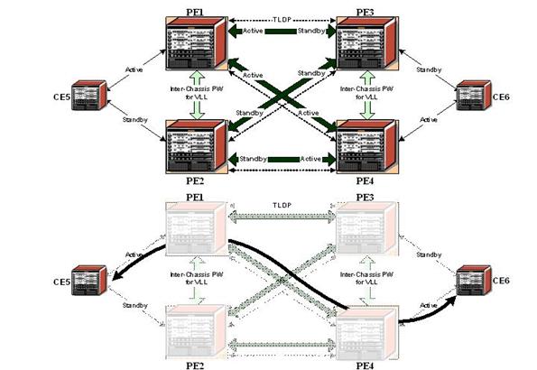
Figure 2 : Access Node resilience
Base Topology
This Configuration Note assumes that following base configuration has been implemented on the PEs:
- Cards, MDAs and ports configured
- Interfaces configured
- IGP configured and converged
- MPLS configured
- SDPs configured between all PE routers
Note that you can choose between OSPF and ISIS as the IGP. Both LDP or RSVP can be used for signaling the transport MPLS labels. Alternatively, GRE can be used for the transport tunnels.
It does not matter if the SDPs are using LDP, RSVP or GRE. RSVP has the added value of offering FRR to get faster convergence in the core.
In this setup OSPF and LDP are used.
The following commands can be used to check if OSPF has converged and to make sure the SDPs are up:
Note: Any of the PE nodes could be either 7705s or 7750s.
*A:PE1# show router route-table
===============================================================================
Route Table (Router: Base)
===============================================================================
Dest Prefix Type Proto Age Pref
Next Hop[Interface Name] Metric
-------------------------------------------------------------------------------
10.0.0.1/32 Local Local 00h33m00s 0
system 0
10.0.0.2/32 Remote OSPF 00h27m17s 10
10.1.2.2 1000
10.0.0.3/32 Remote OSPF 00h28m37s 10
10.1.3.3 1000
10.0.0.4/32 Remote OSPF 00h25m25s 10
10.1.2.2 2000
10.1.2.0/24 Local Local 00h30m06s 0
toPE2 0
10.1.3.0/24 Local Local 00h30m00s 0
toPE3 0
10.2.4.0/24 Remote OSPF 00h25m25s 10
10.1.2.2 2000
10.3.4.0/24 Remote OSPF 00h28m37s 10
10.1.3.3 2000
-------------------------------------------------------------------------------
No. of Routes: 8
===============================================================================
*A:PE1# show service sdp
===============================================================================
Services: Service Destination Points
===============================================================================
SdpId Adm MTU Opr MTU IP address Adm Opr Deliver Signal
-------------------------------------------------------------------------------
12 0 9190 10.0.0.2 Up Up LDP TLDP
13 0 9190 10.0.0.3 Up Up LDP TLDP
14 0 9190 10.0.0.4 Up Up LDP TLDP
-------------------------------------------------------------------------------
Number of SDPs : 3
MC-LAG Configuration
LAG configuration on CEs
Auto-negotiation needs to be switched off (or configured to limited) on all ports that will be included into the LAG.
Configure LACP on the LAG. At least 1 side of the LAG needs to be configured in ‘active’ mode.
*A:CE5# configure port 1/1/[1..4] ethernet no autonegotiate
*A:CE5# configure port 1/1/[1..4] no shut
*A:CE5# configure lag 1 port 1/1/1 sub-group 1
*A:CE5# configure lag 1 port 1/1/4 sub-group 2
*A:CE5# configure lag 1 lacp active
*A:CE5# configure lag 1 no shutdown
LAG configuration on PEs
The PE ports facing the CEs have to be configured as access ports since they will be used in the Redundant PW service. The LAG also needs to be configured in mode access.
Remark: the LAG encapsulation type (null|dot1q|qinq) must match the port encapsulation type of the LAG members.
Auto-negotiation needs to be switched off (or configured to limited).
Configure LACP on the LAG. At least 1 side of the LAG needs to be configured in ‘active’ mode.
*A:PE1# configure port 1/1/[1..2] ethernet no autonegotiate
*A:PE1# configure port 1/1/[1..2] ethernet mode access
*A:PE1# configure port 1/1/[1..2] no shut
*A:PE1# configure lag 1 mode access
*A:PE1# configure lag 1 port 1/1/1 sub-group 1
*A:PE1# configure lag 1 port 1/1/2 sub-group 2
*A:PE1# configure lag 1 lacp active
*A:PE1# configure lag 1 no shutdown
MC-LAG configuration on PE1 and PE2
The redundant PEs must act as 1 virtual node toward the CE. They have to communicate the same LACP parameters to the CE side.
3 parameters uniquely identify a LAG instance:
- lacp-key
- system-id
- system-priority
These 3 parameters must be configured with the same value on both redundant PEs.
Configure multi-chassis redundancy with a peering session toward the redundant PE system address and enable mc-lag redundancy.
*A:PE1# configure redundancy multi-chassis
*A:PE1>config>redundancy>multi-chassis# info
----------------------------------------------
peer 10.0.0.2 create
mc-lag
lag 1 lacp-key 1 system-id 00:00:00:00:00:01 system-priority 100
no shutdown
exit
no shutdown
exit
----------------------------------------------
*A:PE2# configure redundancy multi-chassis
*A:PE2>config>redundancy>multi-chassis# info
----------------------------------------------
peer 10.0.0.1 create
mc-lag
lag 1 lacp-key 1 system-id 00:00:00:00:00:01 system-priority 100
no shutdown
exit
no shutdown
exit
----------------------------------------------
MC-LAG Verification
Verify MC peers
The source IP address can be configures with the command:
*A:PE1# configure redundancy multi-chassis
*A:PE1>config>redundancy>multi-chassis# peer 10.0.0.2 source-address 10.0.0.1
Authentication can also be configured:
*A:PE2# configure redundancy multi-chassis
*A:PE2>config>redundancy>multi-chassis# peer 10.0.0.1 authentication-key Alcatel
Remark: when configuring authentication or a source address the MC peer needs to be shutdown first.
If source IP address and authentication are configured the result looks like:
*A:PE1# show redundancy multi-chassis sync
===============================================================================
Multi-chassis Peer Table
===============================================================================
Peer
-------------------------------------------------------------------------------
Peer IP Address : 10.0.0.2
Authentication : Enabled
Source IP Address : 10.0.0.1
Admin State : Enabled
===============================================================================
===============================================================================
Verify MC-LAG peer status and LAG parameters
*A:PE1# show redundancy multi-chassis mc-lag peer 10.0.0.2
===============================================================================
Multi-Chassis MC-Lag Peer 10.0.0.2
===============================================================================
Last Changed : 03/07/2007 17:38:53
Admin State : Up Oper State : Up
KeepAlive : 10 deci-seconds Hold On Ngbr Failure : 3
-------------------------------------------------------------------------------
Lag Id Lacp Key Remote Lag Id System Id Sys Prio Last Changed
-------------------------------------------------------------------------------
1 1 1 00:00:00:00:00:01 100 03/07/2007 17:40:17
-------------------------------------------------------------------------------
Number of LAGs : 1
===============================================================================
In this example the Lag-Id is 1 on both redundant PEs. This is not mandatory. If the Lag-Id on PE2 is e.g. 2, the following should be configured on PE1:
*A:PE1# configure redundancy multi-chassis
*A:PE1>config>redundancy>multi-chassis# peer 10.0.0.2 mc-lag lag 1 remote-lag 2 lacp-key 1 system-id 00:00:00:00:00:01 system-priority 100
Verify MC-LAG status
*A:PE1# show lag 1
===============================================================================
Lag Data
===============================================================================
Lag-id Adm Opr Port-Threshold Up-Link-Count MC Act/Stdby
-------------------------------------------------------------------------------
1 up down 0 0 standby
===============================================================================
*A:PE2# show lag 1
===============================================================================
Lag Data
===============================================================================
Lag-id Adm Opr Port-Threshold Up-Link-Count MC Act/Stdby
-------------------------------------------------------------------------------
1 up up 0 2 active
===============================================================================
In this case the Lag on PE2 is Active/Operationally up whereas the Lag on PE1 is Standby/Operationally down.
The selection criteria by default is highest # of links and priority. In this example the # of links and the priority of the links is the same on both redundant PEs. Whichever PE’s LAG gets in operational up status first will be the active.
LAG ports of one PE could be preferred over the other PE by configuring port priority (e.g. the following command lowers the priority of the LAG ports on PE1, thus giving this LAG higher preference).
*A:PE1# configure lag 1 port 1/1/1 priority 10
Note : lower S priority is preferred
Verify detailed MC-LAG status on PE1
*A:PE1# show lag 1 detail
===============================================================================
LAG Details
===============================================================================
Description:
-------------------------------------------------------------------------------
Details
-------------------------------------------------------------------------------
Lag-id : 1 Mode : access
Adm : up Opr : up
Thres. Exceeded Cnt : 19 Port Threshold : 0
Thres. Last Cleared : 03/07/2007 19:57:18 Threshold Action : down
Dynamic Cost : false Encap Type : null
Configured Address : 1e:2f:ff:00:01:41 Lag-IfIndex : 1342177281
Hardware Address : 1e:2f:ff:00:01:41 Adapt Qos : distribute
Hold-time Down : 0.0 sec
LACP : enabled Mode : active
LACP Transmit Intvl : fast LACP xmit stdby : enabled
Selection Criteria : highest-count Slave-to-partner : disabled
Number of sub-groups: 1 Forced : -
System Id : 1e:2f:ff:00:00:00 System Priority : 32768
Admin Key : 32768 Oper Key : 1
Prtr System Id : 1e:2d:ff:00:00:00 Prtr System Priority : 32768
Prtr Oper Key : 32768
MC Peer Address : 10.0.0.2 MC Peer Lag-id : 1
MC System Id : 00:00:00:00:00:01 MC System Priority : 100
MC Admin Key : 1 MC Active/Standby : active
MC Lacp ID in use : true MC extended timeout : false
MC Selection Logic : peer decided
MC Config Mismatch : no mismatch
-------------------------------------------------------------------------------
Port-id Adm Act/Stdby Opr Primary Sub-group Forced Prio
-------------------------------------------------------------------------------
1/1/1 up active up yes 1 - 10
1/1/2 up active up 1 - 10
-------------------------------------------------------------------------------
Port-id Role Exp Def Dist Col Syn Aggr Timeout Activity
-------------------------------------------------------------------------------
1/1/1 actor No No Yes Yes Yes Yes Yes Yes
1/1/1 partner No No Yes Yes Yes Yes Yes Yes
1/1/2 actor No No Yes Yes Yes Yes Yes Yes
1/1/2 partner No No Yes Yes Yes Yes Yes Yes
===============================================================================
After changing the Lag port priorities the Lag on PE1 is in up/up state and the ports are in up/active/up status.
MC-LAG configuration on PE3 and PE4
The MC-Lag configuration on PE3 and PE4 is similar to the configuration on PE1 and PE2. In this case the priority of the Lag port on PE4 is lowered to obtain the behaviour in figure 2 where the Lags on PE1 and PE4 are active.
PW Configuration
Configure an Epipe service on every PE and create endpoints x and y. Traffic can only be forwarded between 2 endpoints, i.e. it is not possible for objects associated with the same endpoint to forward traffic to each other.
Associate the SAPs and spoke-SDPs with the endpoints like shown in Figure 2.
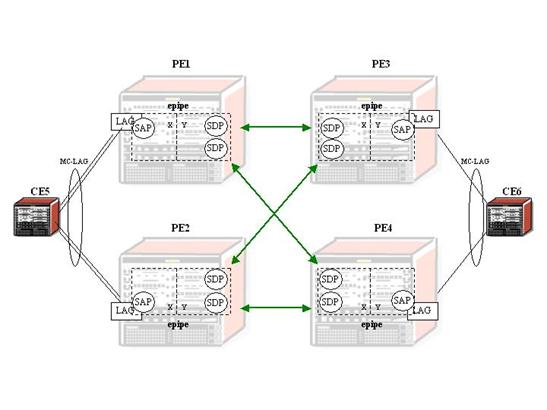
Figure 3: association of SAPs/SDPs and endpoints
*A:PE1# configure service epipe 50
*A:PE1>config>service>epipe# info
----------------------------------------------
endpoint "x" create
exit
endpoint "y" create
exit
sap lag-1 endpoint "x" create
exit
spoke-sdp 13:50 endpoint "y" create
exit
spoke-sdp 14:50 endpoint "y" create
exit
no shutdown
----------------------------------------------
Likewise, an Epipe service, endpoints, SAPs and spoke-SDPs need to be configured on the other PE routers.
PW Verification
Verify service status
*A:PE1# show service service-using
===============================================================================
Services
===============================================================================
ServiceId Type Adm Opr CustomerId Last Mgmt Change
-------------------------------------------------------------------------------
50 Epipe Up Up 1 03/07/2007 21:27:09
-------------------------------------------------------------------------------
Matching Services : 1
-------------------------------------------------------------------------------
===============================================================================
A:PE2# show service service-using
===============================================================================
Services
===============================================================================
ServiceId Type Adm Opr CustomerId Last Mgmt Change
-------------------------------------------------------------------------------
50 Epipe Up Down 1 02/27/2002 20:24:41
-------------------------------------------------------------------------------
Matching Services : 1
-------------------------------------------------------------------------------
===============================================================================
*A:PE3# show service service-using
===============================================================================
Services
===============================================================================
ServiceId Type Adm Opr CustomerId Last Mgmt Change
-------------------------------------------------------------------------------
50 Epipe Up Down 1 03/07/2007 21:31:44
-------------------------------------------------------------------------------
Matching Services : 1
-------------------------------------------------------------------------------
===============================================================================
*A:PE4# show service service-using
===============================================================================
Services
===============================================================================
ServiceId Type Adm Opr CustomerId Last Mgmt Change
-------------------------------------------------------------------------------
50 Epipe Up Up 1 03/07/2007 22:05:10
-------------------------------------------------------------------------------
Matching Services : 1
-------------------------------------------------------------------------------
===============================================================================
The Epipe service on PE2 and PE3 is Down and Up on PE1 and PE4. This reflects the behaviour shown in figure 2. Note that after configuring ICB spoke-SDPs (described later in this document) the Epipe will be in up/up status on all PE routers.
Verify SDP status
Flags indicate local events and Peer PW Bits indicate the status of the peer. Here is an example taken on PE2:
A:PE2# show service id 50 sdp 23:50 detail
===============================================================================
Service Destination Point (Sdp Id : 23:50) Details
===============================================================================
-------------------------------------------------------------------------------
Sdp Id 23:50 -(10.0.0.3)
-------------------------------------------------------------------------------
SDP Id : 23:50 Type : Spoke
VC Type : Ether VC Tag : n/a
Admin Path MTU : 0 Oper Path MTU : 9190
Far End : 10.0.0.3 Delivery : LDP
Admin State : Up Oper State : Down
Acct. Pol : None Collect Stats : Disabled
Ingress Label : 131067 Egress Label : 131065
Ing mac Fltr : n/a Egr mac Fltr : n/a
Ing ip Fltr : n/a Egr ip Fltr : n/a
Ing ipv6 Fltr : n/a Egr ipv6 Fltr : n/a
Admin ControlWord : Not Preferred Oper ControlWord : False
Last Status Change : 02/25/2002 22:19:55 Signaling : TLDP
Last Mgmt Change : 02/27/2002 20:06:53
Endpoint : y Precedence : 4
Flags : SapOperDown
Peer Pw Bits : lacIngressFault lacEgressFault pwFwdingStandby
Peer Fault Ip : None
Peer Vccv CV Bits : lspPing
Peer Vccv CC Bits : mplsRouterAlertLabel
MAC Pinning : Disabled
KeepAlive Information :
Admin State : Disabled Oper State : Disabled
Hello Time : 10 Hello Msg Len : 0
Max Drop Count : 3 Hold Down Time : 10
Statistics :
I. Fwd. Pkts. : 0 I. Dro. Pkts. : 0
E. Fwd. Pkts. : 0 E. Fwd. Octets : 0
-------------------------------------------------------------------------------
Number of SDPs : 1
-------------------------------------------------------------------------------
===============================================================================
In this example there is a flag ‘SapOperDown’ set. The SAP is down because the LAG is in standby/down status.
Note also that the remote side of the SPD is sending ‘lacIngressFault lacEgressFault pwFwdingStandby’ flags. This is because the epipe service on PE3 is down for the same reason.
Now you can test link and node protection. The access links are protected by the MC-LAG, the PE routers are protected by the combination of MC-LAG/PW Redundancy. The SDPs can be protected by FRR in the case of RSVP-TE.
Configure an interface on the LAG of the CE routers. Send traffic between the CE routers and test convergence.
Inter-Chassis Backup (ICB) PW configuration
Note that in this setup the configuration of ICBs is optional. It can be used to protect in-flight packets during LAG link transition.
Configure ICB SDPs and associate them to endpoints like shown in Figure 3.
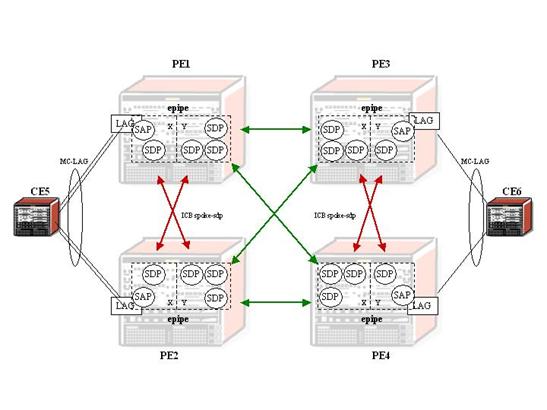
Figure 4: ICB spoke-SDPs and their association with the endpoints
Two ICB spoke-SDPs need to be configured in the Epipe service on each PE router, 1 in each endpoint. Different sdp-ids can be used but this is not necessary since the far-end will be the same. The vc-id must be different however.
The ICB spoke-SDPs must cross, i.e. one end should be associated with endpoint ‘x’ and the other end (on the other PE) should be associated with endpoint ’y’.
Note that after configuring the ICB spoke-SDPs the Epipe service will be up/up on all 4 PE routers.
Only 1 spoke-SDP will be forwarding. If
there is an ICB and a SAP in an endpoint the ICB will only forward if the SAP
goes down. If an ICB resides in an endpoint together with other spoke-SDPs the
ICB will only forward if there is no other active spoke-SDP.
The following extracts show the complete Epipe service configuration on each
PE:
*A:PE1>config>service>epipe# info
----------------------------------------------
endpoint "x" create
exit
endpoint "y" create
exit
sap lag-1 endpoint "x" create
exit
spoke-sdp 13:50 endpoint "y" create
exit
spoke-sdp 14:50 endpoint "y" create
exit
spoke-sdp 12:50 endpoint "x" icb create
exit
spoke-sdp 12:60 endpoint "y" icb create
exit
no shutdown
*A:PE2>config>service>epipe# info
----------------------------------------------
endpoint "x" create
exit
endpoint "y" create
exit
sap lag-1 endpoint "x" create
exit
spoke-sdp 23:50 endpoint "y" create
exit
spoke-sdp 24:50 endpoint "y" create
exit
spoke-sdp 21:50 endpoint "y" icb create
exit
spoke-sdp 21:60 endpoint "x" icb create
exit
no shutdown
*A:PE3>config>service>epipe# info
----------------------------------------------
endpoint "x" create
exit
endpoint "y" create
exit
sap lag-1 endpoint "y" create
exit
spoke-sdp 31:50 endpoint "x" create
exit
spoke-sdp 32:50 endpoint "x" create
exit
spoke-sdp 34:50 endpoint "x" icb create
exit
spoke-sdp 34:60 endpoint "y" icb create
exit
no shutdown
*A:PE4>config>service>epipe# info
----------------------------------------------
endpoint "x" create
exit
endpoint "y" create
exit
sap lag-1 endpoint "y" create
exit
spoke-sdp 41:50 endpoint "x" create
exit
spoke-sdp 42:50 endpoint "x" create
exit
spoke-sdp 43:50 endpoint "y" icb create
exit
spoke-sdp 43:60 endpoint "x" icb create
exit
no shutdown
Verification
Verification of active objects for each Endpoint
The following command shows which objects are configured for each endpoint and which is the active object at this moment:
*A:PE1# show service id 50 endpoint
===============================================================================
Service 50 endpoints
===============================================================================
Endpoint name : x
Revert time : 0
Act Hold Delay : 0
Tx Active : lag-1
-------------------------------------------------------------------------------
Members
-------------------------------------------------------------------------------
SAP : lag-1
Spoke-sdp : 12:50 Precedence:4 (icb)
===============================================================================
Endpoint name : y
Revert time : 0
Act Hold Delay : 0
Tx Active : 14:50
-------------------------------------------------------------------------------
Members
-------------------------------------------------------------------------------
Spoke-sdp : 12:60 Precedence:4 (icb)
Spoke-sdp : 13:50 Precedence:4
Spoke-sdp : 14:50 Precedence:4
===============================================================================
===============================================================================
Note that on PE1 the SAP and the spoke-SDP 14:50 are active. The other objects do not forward traffic.
On PE2 this looks like:
*A:PE2# show service id 50 endpoint
===============================================================================
Service 50 endpoints
===============================================================================
Endpoint name : x
Revert time : 0
Act Hold Delay : 0
Tx Active : 21:60
-------------------------------------------------------------------------------
Members
-------------------------------------------------------------------------------
SAP : lag-1
Spoke-sdp : 21:60 Precedence:4 (icb)
===============================================================================
Endpoint name : y
Revert time : 0
Act Hold Delay : 0
Tx Active : 24:50
-------------------------------------------------------------------------------
Members
-------------------------------------------------------------------------------
Spoke-sdp : 21:50 Precedence:4 (icb)
Spoke-sdp : 23:50 Precedence:4
Spoke-sdp : 24:50 Precedence:4
===============================================================================
===============================================================================
In this case the ICB towards PE1 and the spoke-SDP 24:50 are active.
Verification of convergence
Convergence can be tested by sending traffic between the 2 CE devices and failing access links or PE routers.
Figure 4, Figure 5 and Figure 6 give an overview of how traffic is expected to flow, the tx-active objects in the endpoints and the Flags and Peer Pw Bits of the spoke-SDPs.
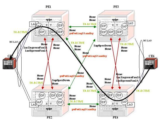
Figure 5: normal operation
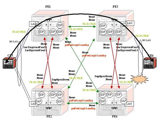
Figure 6: access link failure
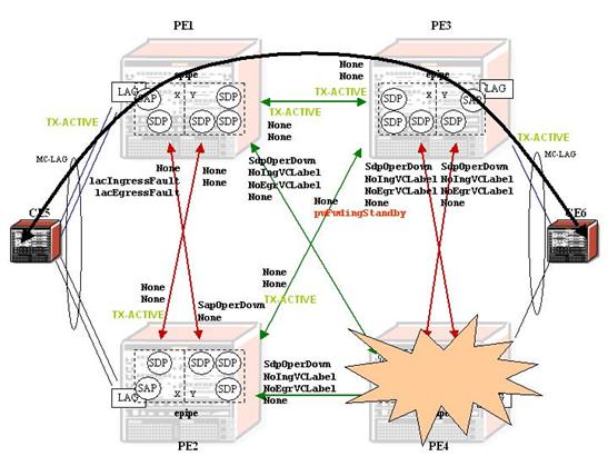
Figure 7: acces node Failure
Figure 7, Figure 8 and Figure 9 show convergence without ICBs.
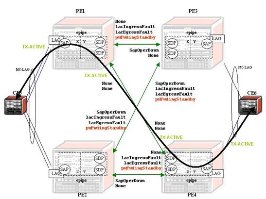
Figure 8: normal operation/no ICBs
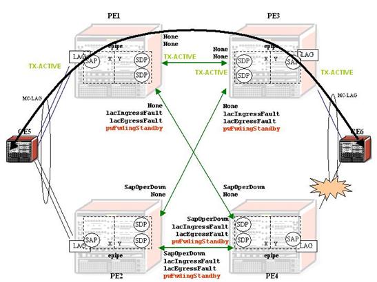
Figure 9: access link failure / no ICBs
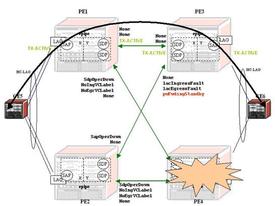
Figure 10: Access node failure / No ICBs