4. Mirroring
4.1. In This Chapter
This chapter provides information about mirroring support on the 7705 SAR.
Topics in this chapter include:
4.2. Mirroring Overview
To assist in troubleshooting complex operational problems, certain packets may need to be examined as they traverse the network. One way to accomplish this is with an overlay of network analyzers established at multiple PoPs, together with skilled technicians to operate them to decode the data provided. This method of traffic mirroring often requires setting up complex filters in multiple switches and/or routers. These, at best, are only able to mirror from one port to another on the same device.
Nokia’s support for port mirroring on the 7705 SAR extends and integrates these capabilities into the network and provides significant operational benefits. Each router can mirror packets to any Ethernet interface destination point in the network.
This capability also extends beyond troubleshooting services. Telephone companies have the ability to obtain itemized calling records and wiretaps where legally required by investigating authorities. The process can be complex and costly to carry out on data networks. Service mirroring simplifies these via mirroring of the SAP port, and reduces costs through centralization of analysis tools and skilled technicians.
Original packets are forwarded while a copy is sent out the mirrored port to the mirroring (destination) port. Mirroring allows an operator to see the actual traffic on a port with a sniffer sitting in a central location. In many cases, this reduces the need for a separate, costly overlay sniffer network.
The mirrored frame size that is to be transmitted to the mirror destination can be explicitly configured by using slicing features. This enables mirroring of only the parts needed for analysis while minimizing network resource usage. For example, only the headers can be copied for analysis, protecting the integrity and security of customer data, or conversely, copying the full packet, including customer data.
Mirroring is supported on the following hardware:
- 2-port 10GigE (Ethernet) Adapter card (only on the 2.5 Gb/s v-port)
- 6-port Ethernet 10Gbps Adapter card
- 8-port Ethernet Adapter card, version 2
- 8-port Gigabit Ethernet Adapter card version 1
- 8-port Gigabit Ethernet Adapter card version 2
- 8-port Gigabit Ethernet Adapter card version 3
- 10-port 1GigE/1-port 10GigE X-Adapter card version 1
- 10-port 1GigE/1-port 10GigE X-Adapter card version 2
- Packet Microwave Adapter card
- 2-port 10GigE (Ethernet) module (only on the 2.5 Gb/s v-port)
- 4-port SAR-H Fast Ethernet module
- 6-port SAR-M Ethernet module
- 7705 SAR-A
- 7705 SAR-Ax
- 7705 SAR-H
- 7705 SAR-Hc
- 7705 SAR-M
- 7705 SAR-W
- 7705 SAR-Wx
- 7705 SAR-X
4.2.1. Mirroring Implementation
The 7705 SAR supports port mirroring only. The network processor of the datapath preserves the original packet throughout the forwarding and mirroring process, making any necessary packet changes, such as adding encapsulation, on a separate copy.
Nokia’s implementation of packet mirroring is based on the following assumptions.
- Ingress and egress packets are mirrored as they appear on the wire. This is important for troubleshooting encapsulation and protocol issues.
- When mirroring at ingress, the network processor sends an exact copy of the original ingress packet to the mirror destination while normal forwarding proceeds on the original packet.
- When mirroring is at egress, the system performs normal packet handling on the egress packet, encapsulating it for the destination interface. A copy of the forwarded packet is forwarded to the mirror destination. Because the mirror copy of the packet is created before egress queuing, the mirrored packet stream may include copies of packets that are discarded in egress queues, such as during congestion or rate limiting.
- Mirroring supports tunnel destinations.
- Remote destinations are reached by encapsulating the ingress or egress packet within an SDP, like the traffic for distributed VPN connectivity services. At the remote destination, the tunnel encapsulation is removed and the packet is forwarded out a local SAP.
4.2.2. Mirror Sources and Destinations
Mirror sources and destinations have the following characteristics.
- Sources and destinations can be on the same router (local) or on two different routers (remote).
- Mirror destinations can terminate on egress virtual ports, which allows multiple mirror destinations to send to the same packet decoding device, delimited by IEEE 802.1Q (referred to as dot1q) tags. This is helpful when troubleshooting a multi-port issue within the network.When multiple mirror destinations terminate on the same egress port, the individual dot1q tags can provide a DTE/DCE separation between the mirror sources.
- Packets ingressing a port can have a mirror destination separate from packets egressing the same port or a different port (the ports can be on separate nodes).
- Multiple mirror destinations are supported (local and/or remote) on a single node.
- The operational state of a mirror destination depends on the state of all the outputs of the mirror. The mirror destination will go operationally down if all the outputs are down (for example, all mirror-dest>sap and mirror-dest>spoke-sdp objects are down. The state of a mirror destination does not depend on inputs such as SDPs configured under mirror-dest>remote-source or debug>mirror-source entries.
4.2.2.1. Local and Remote Mirroring
Mirrored frames can be copied and sent to a specific local destination on the router (local mirroring) or copies can be encapsulated and sent to a different router (remote mirroring). This functionality allows network operators to centralize network analyzer (sniffer) resources, and also the technical staff who operate them.
The router allows multiple concurrent mirroring sessions so that traffic from more than one ingress mirror source can be mirrored to the same or different egress mirror destinations.
Remote mirroring uses an SDP, which acts as a logical way of directing traffic from one router to another through a unidirectional service tunnel. The SDP terminates at the far-end router, which directs packets to the correct destination on that device.
The SDP configuration from the mirrored device to a far-end router requires a return path SDP from the far-end router back to the mirrored router. Each device must have an SDP defined for every remote router to which it wants to provide mirroring services. SDPs must be created first, before services can be configured.
4.2.2.2. Slicing
Another service mirroring refinement is slicing, which only mirrors a specified packet length from each frame. This is useful to monitor network usage without having to copy the actual data. Slicing enables the mirroring of larger frames than the destination packet decoding equipment can handle. It also allows conservation of mirroring resources by limiting the size of the stream of packets through the router and the core network.
When a mirror slice-size is defined, a threshold that truncates a mirrored frame to a specific size is created. For example, if the value of 256 bytes is defined, up to the first 256 bytes of the frame are transmitted to the mirror destination. The original frame is not affected by the truncation. Mirrored frames will grow larger as encapsulations are added when packets are transmitted through the network core or out the mirror destination SAP to the packet/protocol decoding equipment.
The transmission of a sliced or non-sliced frame is also dependent on the mirror destination SDP path MTU and/or the mirror destination SAP physical MTU. Packets that require a larger MTU than the mirroring destination supports are discarded if the defined slice size does not truncate the packet to an acceptable size.
4.2.3. Mirroring Performance
Replication of mirrored packets can affect performance and should be used carefully. The 7705 SAR, making use of network processor based forwarding, allows efficient mirror service scaling and, at the same time, allows a large amount of data to be mirrored with minimal performance impact. When a mirror destination is configured, the packet slice option can truncate mirrored packets to the destination, which minimizes replication and tunneling overhead.
When a packet at port ingress is mirrored, one extra buffer per packet is used. For more information, refer to the “Buffer Allocation for Multicast Traffic” section in the 7705 SAR OS Quality of Service Guide.
4.2.4. Mirroring Configuration
Configuring mirroring is similar to creating a unidirectional service. Mirroring requires the configuration of:
- mirror source — the port or ports from which traffic is to be mirrored
- mirror destination — the location to send the mirrored traffic, where the sniffer will be located
Figure 20 shows a local mirror service configured on a 7705 SAR (SAR-1).
- Port 1/1/2 is specified as the source. Mirrored traffic ingressing and egressing this port will be sent to port 1/1/3.
- SAP 1/1/3 is specified as the destination. The sniffer is physically connected to this port. Mirrored traffic ingressing and egressing port 1/1/2 is sent here. SAP, encapsulation requirements, packet slicing, and mirror classification parameters are configured for the destination port. SDPs are not used in local mirroring.
Figure 20: Local Mirroring Example
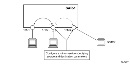
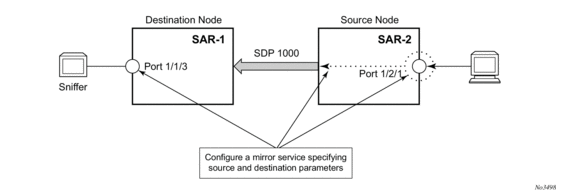
Figure 21 shows a remote mirror service configured as SAR-2 as the mirror source and SAR-1 as the mirror destination. Mirrored traffic ingressing and egressing port 1/2/1 (the source) on SAR-2 is handled in the following ways.
- Port 1/2/1 is specified as the mirror source port. Parameters are defined to select specific traffic ingressing and egressing this port.
- Destination parameters are defined to specify where the mirrored traffic will be sent. In this case, mirrored traffic will be sent to a SAP configured as part of the mirror service on port 1/1/3 on SAR-1 (the mirror destination).
- SAR-1 decodes the service ID and sends the traffic out of port 1/1/3.
- The sniffer is physically connected to port 1/1/3. SAP, encapsulation requirements, packet slicing, and mirror classification parameters are configured for the destination port.
Figure 21: Remote Mirroring Example
4.3. Configuration Notes
This section describes mirroring configuration caveats.
- Multiple mirroring service IDs (mirror destinations) may be created within a single system.
- A mirrored source can only have one destination.
- The destination mirroring service IDs and service parameters are persistent between router reboots and are included in the configuration saves.Mirror source criteria configuration (defined in debug>mirror-source) is not preserved in a configuration save (admin save). Debug mirror source configuration can be saved using admin>debug-save.
- Physical layer problems such as collisions and jabbers are not mirrored. Typically, only complete packets are mirrored.
- When starting or shutting down mirroring on mirror destinations, the following must be considered.
- The default state for a mirror destination service ID is shutdown. You must issue a no shutdown command to enable the feature.
- When a mirror destination service ID is shut down, mirrored packets associated with the service ID are not accepted from its mirror source or remote source. The associated mirror source is put into an operationally down mode. Mirrored packets are not transmitted out the SAP or SDP. Each mirrored packet is silently discarded. If the mirror destination is a SAP, the SAP’s discard counters are incremented.
- Issuing the shutdown command causes the mirror destination service or its mirror source to be put into an administratively down state. Mirror destination service IDs must be shut down first in order to delete a service ID, SAP, or SDP association from the system.
When starting or shutting down mirroring on mirror sources, the following must be considered.- The default state for a mirror source for a given mirror destination service ID is no shutdown. You must enter a shutdown command to deactivate (disable) mirroring from that mirror source.
- Mirror sources do not need to be shut down to remove them from the system. When a mirror source is shut down, mirroring is terminated for all sources defined locally for the mirror destination service ID.
4.4. Configuring Mirroring with CLI
This section provides information about configuring service mirroring using CLI.
Topics in this section include:
4.4.1. Mirror Configuration Overview
Mirroring can be organized into the following logical entities.
- The mirror source is the location where ingress or egress traffic specific to a port is to be mirrored (copied). The original frames are not altered or affected in any way.
- An SDP is used to define the mirror destination on the source router to point to a remote destination (another router).
- A SAP is defined in local and remote mirror services as the mirror destination to which the mirrored packets are sent.
4.5. Basic Mirroring Configuration
Mirror destination parameters must include:
- a mirror destination ID (same as the mirror source service ID)
- a mirror destination SAP or SDP
Mirror source parameters must include:
- a mirror service ID (same as the mirror destination service ID)
- the source type (port)
The following example shows a configuration of a local mirrored service where the source and destinations are on the same device.
The following example shows a mirror source configuration:
The following example shows a configuration of a remote mirrored service where the source is a port on SAR-1 and the destination is a SAP on SAR-2:
4.5.1. Mirror Classification Rules
-Nokia’s implementation of mirroring can be performed by configuring port parameters to select network traffic.
The port command associates a port with a mirror source. The port is identified by the port ID.
The following shows the port-id syntax for the port command:
port-id: | slot/mda/port | ||
lag-id | 1 to 32 | ||
egress | keyword | ||
ingress | keyword | ||
The defined port can be an Ethernet port or a Link Aggregation Group (LAG) ID. When a LAG ID is given as the port ID, mirroring is enabled on all ports making up the LAG. Ports that are circuit-emulation (CEM) and PPP bundle groups cannot be used as a mirror source.
Mirror sources can be ports in either access or network mode. Port mirroring is supported in the combinations shown in Table 34:
Table 34: Mirror Source Port Requirements
Port Type | Port Mode | Port Encapsulation Type |
Ethernet | access | dot1q, null, qinq |
Ethernet | network | dot1q, null |
Ethernet | hybrid | dot1q |
4.6. Common Configuration Tasks
This section provides a brief overview of the tasks that must be performed to configure both local and remote mirror services and provides the CLI command syntax. Local and remote mirror source and mirror destination components must be configured under the same service ID context.
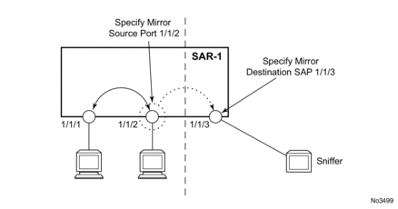
Each local mirrored service (within the same router) (Figure 22) requires the following configurations:
- Specify the mirror destination (SAP).
- Specify the mirror source (port).
Figure 22: Local Mirrored Service Tasks
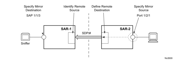
Each remote mirrored service (across the network core) (Figure 23) requires the following configurations:
- Define the remote destination (SDP).
- Identify the remote source (the device allowed to mirror traffic to this device).
- Specify the mirror destination (SAP).
- Specify the mirror source (port).
Figure 23: Remote Mirrored Service Tasks
4.6.1. Configuring a Local Mirror Service
To configure a local mirror service, the source and destinations must be located on the same router. Local mirror source and mirror destination components must be configured under the same service ID context.
The mirror-source commands are used as traffic selection criteria to identify traffic to be mirrored at the source.
The mirror-dest commands are used to specify where the mirrored traffic is to be sent, the forwarding class, and the size of the packet.
The following output shows an example of a local mirrored service. On SAR-1, mirror service 103 is mirroring egress and ingress traffic on port 1/1/24 and sending the mirrored packets to SAP 1/1/25:
The following output shows debug mirroring information:
4.6.2. Configuring SDPs for Mirroring
This section provides a brief overview of the tasks that must be performed to configure SDPs and provides the CLI commands. For more information about service configuration, refer to the 7705 SAR OS Services Guide.
The following SDP characteristics apply:
- The SDP must be configured for GRE or MPLS encapsulation.
- Each distributed service must have an SDP defined for every remote 7705 SAR to provide Epipe, VPLS, or mirrored services.
- A distributed service must be bound to an SDP. By default, no SDP is associated with a service. Once an SDP is created, services can be associated with that SDP.
- An SDP is not specific to any one service or any type of service. An SDP can have more than one service bound to it.
- For SDPs use remote-source>far-end entries. Remote source far-end details are configured in the destination node.
- To configure an MPLS SDP, LSPs must be configured first and then the LSP-to-SDP association must be explicitly created.
To configure a basic SDP, perform the following steps:
- Select an originating node.
- Create an SDP ID.
- Select an encapsulation type.
- Select the far-end node.
To configure the return path SDP, perform the same steps on the far-end router.
Use the following CLI syntax to create an SDP and select an encapsulation type. If you do not specify GRE or MPLS, the default encapsulation type is GRE.
| Note: When you specify the far-end IP address, you are creating the tunnel. In essence, you are creating the path from Point A to Point B. Use the show service sdp command to display the qualifying SDPs. |
On the mirror-source router, configure an SDP pointing toward the mirror-destination router (or use an existing SDP).
On the mirror-destination router, configure an SDP pointing toward the mirror-source router (or use an existing SDP).
The following example shows SDP configurations on both the mirror-source and mirror-destination routers.
4.6.3. Configuring a Remote Mirror Service
For remote mirroring, the source and destination are configured on different routers. Mirror source and mirror destination parameters must be configured under the same service ID context.
For SDPs use remote-source>far-end entries. Remote source far-end details are configured in the destination node.
Figure 24 shows the mirror destination (SAR-1), configuration for mirror service 1216. This configuration specifies that the mirrored traffic coming from the mirror source (10.10.0.91) is to be directed to SAP 1/1/58 and states that the service only accepts traffic from far-end 10.10.0.92 (SAR-2) with an ingress service label of 5678. When a forwarding class is specified, then all mirrored packets transmitted to the destination SAP or SDP override the default (be) forwarding class. The slice size limits the size of the stream of packet through the router and the core network.
Figure 24: Remote Mirrored Service Tasks
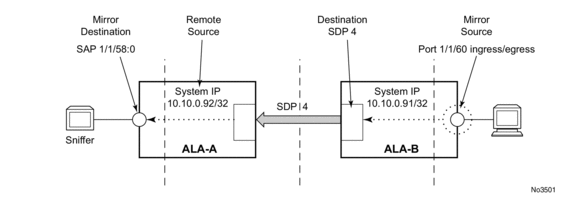
The following example shows the CLI output for configuration of remote mirrored service 1216. The traffic ingressing and egressing port 1/1/60 on 10.10.0.92 (SAR-2) will be mirrored to the destination SAP 1/1/58:0 on SAR-1.
The following example shows the remote mirror destination configured on SAR-2:
The following example shows the mirror source configuration for SAR-2:
The following example shows the SDP configuration from SAR-1 to SAR-2 (SDP 2) and the SDP configuration from SAR-2 to SAR-1 (SDP 4):
4.6.4. Pseudowire Redundancy for Mirror Services Configuration Example
A configuration based on Figure 25 is described in this section.
Figure 25: State Engine for Redundant Service to a Redundant Mirror Service
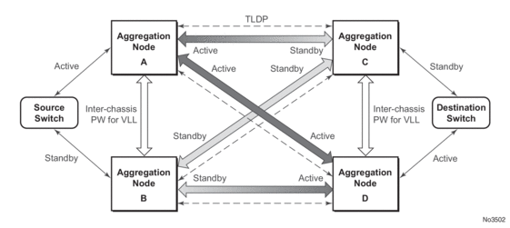
The mirror traffic must be forwarded from the configured debug mirror source together with the mirror dest/remote source (ICB or non-ICB) to either a SAP endpoint or SDP endpoint.
A SAP endpoint is an endpoint with a SAP and with or without an additional ICB spoke. An SDP endpoint is an endpoint with regular and ICB spokes.
Only one tx-active will be chosen for either the SAP endpoint or SDP endpoint. Traffic ingressing into a remote-source ICB will have only ingressing traffic while an ICB spoke will have only egressing traffic.
The ingressing traffic to a remote-source ICB cannot be forwarded out of another ICB spoke.
The following example shows a high-level summary of a configuration; it is not intended to be syntactically correct:
4.6.5. MC-LAG Setup with ICB for Mirror Services Configuration Example
A configuration based on Figure 26 is described in this section.
Figure 26: Remote Mirroring of MC-LAG Ports
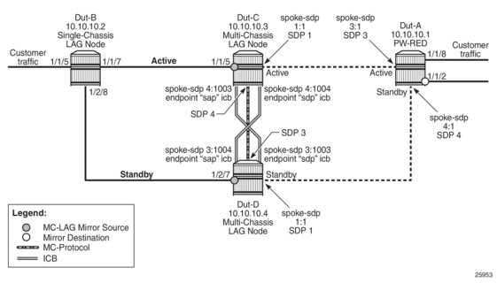
ICB spoke SDPs have been supported for Epipe services in an MC-LAG configuration. ICB spoke SDP improves switch times, provides additional protection in case of network failures, and reduces packet loss when an active endpoint is switched from a failed MC-LAG node to a protection node.
ICB spoke SDPs are now being supported for mirror services in an MC-LAG setup. ICB helps reduce the packet loss of mirrored packets during access MC-LAG switchovers. ICB also provides protection for mirrored packets in case of a network failure.
ICBs must be configured in both directions. Mirroring traffic does not work if only one ICB is configured for mirroring traffic from one MC-LAG node.
The mirroring traffic from both the MC-LAG ports that are mirror sources is mirrored to a common remote mirror destination. The mirror destination receives the mirror traffic from the active MC-LAG port. When an MC-LAG switchover happens due to an active node failure or link failure, the mirror destination will start receiving traffic from the newly activated MC-LAG port.
If there is a network failure on the active network path, the MC-LAG does not switch over. In this case, ICB will provide protection for the data traffic and mirror traffic.
The following example shows the service configuration and the corresponding remote mirroring configuration; it is not intended to be syntactically correct.
Service Configuration with ICB on Dut-C
Service Configuration with ICB on Dut-D
Service Configuration on Dut-A
Mirror Configuration for Dut-C (MC-LAG Port as Mirror Source)
Mirror Configuration for Dut-D (MC-LAG Port as Mirror Source)
Mirror Configuration for Dut-A (Remote Mirror Destination)
4.7. Service Management Tasks
This section describes service management tasks.
4.7.1. Modifying a Local Mirrored Service
Existing mirroring parameters can be modified in the CLI. The changes are applied immediately. The service must be shut down if changes to the SAP are made.
The following example shows the commands to modify parameters for a basic local mirroring service:
The following output shows the local mirrored service modifications:
4.7.2. Deleting a Local Mirrored Service
Existing mirroring parameters can be deleted in the CLI. A shutdown must be issued on a service level in order to delete the service. It is not necessary to shut down or remove SAP or port references to delete a local mirrored service.
The following example shows the commands to delete a local mirrored service:
4.7.3. Modifying a Remote Mirrored Service
Existing mirroring parameters can be modified in the CLI. The changes are applied immediately. The service must be shut down if changes to the SAP are made.
In the following example, the mirror destination is changed from 10.10.10.2 (SAR-2) to 10.10.10.3 (SAR3). The mirror destination service ID on SAR-2 must be shut down first before it can be deleted.
The following example shows the commands to modify parameters for a remote mirrored service:
4.7.4. Deleting a Remote Mirrored Service
Existing mirroring parameters can be deleted in the CLI. A shutdown must be issued on a service level in order to delete the service. It is not necessary to shut down or remove SAP or far-end references to delete a remote mirrored service. To delete a mirrored service with SDP configured, it is necessary to first remove or shut down the SDP.
Mirror destinations must be shut down first before they can be deleted.
In the example, the mirror-destination service ID 105 was removed from the configuration on SAR-1 and SAR-2, thus it does not appear in the info command output.
Since the mirror destination was removed from the configuration on SAR-2, the port information was automatically removed from the debug mirror source configuration.