7. MLDP
7.1. In This Chapter
This chapter provides information to configure Multicast Label Distribution Protocol (MLDP).
Topics in this chapter include:
7.2. Dynamic Multicast Signaling over P2MP in GRT Instance
This feature provides a flexible multicast signaling solution to connect native IP multicast source and receivers running PIM multicast protocol via an intermediate MPLS (P2MP LDP LSP) network. The feature allows each native IP multicast flow to be connected via an intermediate P2MP LSP by dynamically mapping each PIM multicast flow to a P2MP LDP LSP.
The feature uses procedures defined in RFC 6826: Multipoint LDP In-Band Signaling for Point-to-Multipoint and Multipoint-to-Multipoint Label Switched Paths. On the leaf node of a P2MP LSP, PIM signaling is dynamically mapped to P2MP LDP tree setup. On the root node of P2MP LSP, P2MP LDP signaling is handed back to PIM. Due to dynamic mapping of multicast IP flow to P2MP LSP, provisioning and maintenance overhead is eliminated as multicast distribution services are added and removed from the network. Per (S,G) IP multicast state is also removed from the network where P2MP LSPs are used to transport multicast flows.
Figure 5 illustrates dynamic MLDP signaling for IP multicast in GRT.
Figure 5: Dynamic MLDP Signaling for IP Multicast in GRT
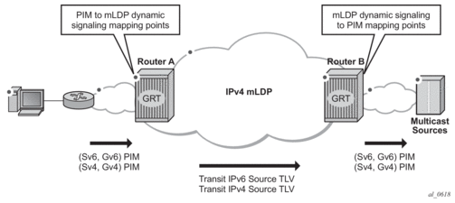
As illustrated in Figure 5, P2MP LDP LSP signaling is initiated from the router that receives PIM JOIN from a downstream router (Router A). To enable dynamic multicast signaling, p2mp-ldp-tree-join must be configured on PIM outgoing interface of Router A. This enables handover of multicast tree signaling from PIM to P2MP LDP LSP. Being a leaf node of P2MP LDP LSP, Router A selects the upstream-hop as the root node of P2MP LDP FEC based on routing table lookup. If an ECMP path is available for a given route, then the number of trees are equally balanced towards multiple root nodes. The PIM Joins are carried in Transit IPv4 (IPv4 PIM SSM) or IPv6 (IPv6 PIM SSM) MLDP TLVs. On the root node of P2MP LDP LSP (Router B), multicast tree signaling is handed back to PIM and propagated upstream as native-IP PIM JOIN.
The feature is supported with IPv4 and IPv6 PIM SSM and IPv4 MLDP. Directly connected IGMP/MLD receivers are also supported with PIM enabled on outgoing interfaces and SSM mapping configured if required.
If multiple criteria exist to setup a multicast flow, the following priority is given as follows:
- Multicast (statically provisioned) over P2MP LSP (RSVP-TE or LDP)
- Dynamic multicast signaling over P2MP LDP
- PIM native-IP multicast
The following are feature caveats:
- A single instance of P2MP LDP LSP is supported between the root and leaf nodes per multicast flow; there is no stitching of dynamic trees.
- Extranet functionality is not supported.
- The router LSA link ID or the advertising router ID must be a routable IPv4 address (including IPv6 into IPv4 MLDP use cases).
- IPv6 PIM with dynamic IPv4 MLDP signaling is not supported with e-BGP or i-BGP with IPv6 next-hop.
- Inter-AS and IGP inter-area scenarios where the originating router is altered at the ASBR and ABR respectively, (hence PIM has no way to create the LDP LSP towards the source), are not supported.
7.3. Inter-AS Non-segmented MLDP
This feature allows multicast services to use segmented protocols and span them over multiple autonomous systems (ASs), as done in unicast services. As IP VPN or GRT services span multiple IGP areas or multiple ASs, either for a network designed to deal with scale or as result of commercial acquisitions, operators may require Inter-AS VPN (unicast) connectivity. For example, an Inter-AS VPN can break the IGP, MPLS and BGP protocols into access segments and core segments, allowing higher scaling of protocols by segmenting them into their own islands. SR OS also allows for similar provision of multicast services and for spanning these services over multiple IGP areas or multiple ASs.
For multicast VPN (MVPN), SR OS previously supported Inter-AS option A/B/C for Rosen MVPN; however, when MPLS was used, only option A was supported for Next Generation Multicast VPN (NG-MVPN) or d-MLDP signaling. MLDP now supports non-segmented MLDP trees for inter-AS solutions, applicable for multicast services in the GRT (Global Routing Table) where they need to ride over MLDP point-to-multipoint tunnels as well as NG-MVPN services.
Refer to the “ECMP Support” subsection of the “Inter-AS Non-segmented MLDP” section in the MPLS Guide for more information.
Refer to the “Dynamic mLDP and Static mLDP Co-existing on Same Node” section in the MPLS Guide for more information.
7.3.1. d-MLDP Inter-AS Trees in GRT
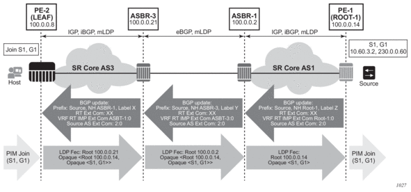
Figure 6 shows the processing required for d-mLDP with non-segmented mLDP Inter-AS trees in GRT (routers in AS3, including ASBR 1, have no route to ROOT-1 in IGP and must use BGP unicast routes to resolve route to ROOT-1 and to multicast source).
PE-1 (ROOT-1) is the root node of the MLDP tree, and PE-2 (LEAF) is the leaf node.
Figure 6: In-band Signaling with Non-segmented Inter-AS MLDP Trees in GRT
7.3.1.1. Routing
BGP unicast routes must advertise to the VRF Route Import Ext Community, identifying the root PE, for the feature to operate properly. Failure to do so will result in PIM Inter-AS joins being dropped.
The community is an address-based community where the global administrator field is the address of the root PE and local administrator field is set to 0 (GRT). No new configuration is required; however, an operator must enable inter-AS VPN and configure export policy to ensure the community is added to the BGP routes as required. The BGP unicast route is propagated across the AS, as shown in Figure 6 (the same processing, not shown, applies to a BGP route specifying address used to build mLDP tree rooted at ROOT-1). The following configuration example shows an export policy configuration.
Static routes must be configured on inter-ASBR LDP-enabled links because the BGP peer uses a host address from the local subnet of the links (for GRT and VPN option C), or the BGP peer uses a system IP address that is not in the base routing table (for VPN option B).
- For system-IP to system-IP, static-routes are required for bringing up the EBGP/LDP session.
- If the link IP is used for creation of EBGP and ILD, then static-routes are not required; however, static-route (host-route) is mandatory on ASBR2 for the resolution of MLDP FEC, as the link LSR ID is not resolved by LDP using a /24 route; it needs a /32 route.
7.3.1.2. Join Processing
To traverse an inter-AS domain, recursive FECs are required (refer to the “Inter-AS Non-segmented MLDP” section in the MPLS Guide for more information).
The operator must enable dynamic signaling on interfaces where Inter-AS joins are expected to be received using the existing configuration (p2mp-ldp-tree-join [ipv4] [ipv6]). Once enabled, the following describes the required processing of a PIM join, as shown in Figure 6.
When the leaf receives a PIM join for group (S1, G1) and, through configuration, knows dynamic signaling is required, the leaf fails to resolve the source S1 via IGP and attempts to resolve route via BGP. The leaf learns that source is reachable via Next-Hop ASBR3 and the route was advertised by PE1 (Root-1) (from VRF Import Ext Community). PE2 (leaf) sources a Recursive mLDP FEC with a root node of ASBR3, and an opaque value containing the MLDP in-band signaling information identifying the (S1, G1) group and the Root-1 (the root of the inter-AS non-segmented MLDP tree), as shown below:
LEAF FEC {Root = ASBR3, Opaque Value = {Root: ROOT-1, Opaque Value (S1, G1)}}
The FEC is forwarded using IGP to ASBR3.
When the Recursive MLDP FEC arrives at ASBR3, it notes that it is the identified root node in the local AS, and that the opaque value is a Recursive Opaque Value. Because ASBR3 fails to resolve the Recursive FEC’s root (Root-1) in IGP, ASBR3 attempts to resolves the root via BGP. Similarly to processing on LEAF, this yields a Next-Hop of ASBR1. ASBR3 creates a new mLDP FEC element with a root node of ASBR1, and the Opaque value as per received opaque value, as shown below:
ASBR3 FEC {Root = ASBR1, Opaque Value = {Root: Root-1, Opaque Value: (S1, G1)}}
ASBR 3 forwards the FEC using IGP or eBGP.
When the MLDP FEC arrives at ASBR1, it notes that it is the identified root node, and that the opaque value is a Recursive Opaque value. Because ASBR1 can resolve the Recursive FEC’s root (Root-1) via IGP, no further recursive processing is required. ASBR 1 forwards mLDP FEC containing in-band signaling using IGP towards ROOT-1.
7.3.2. ASBR Support of PE Functionality
Figure 7 displays remote and local ASBRs.
Figure 7: Remote and Local ASBRs
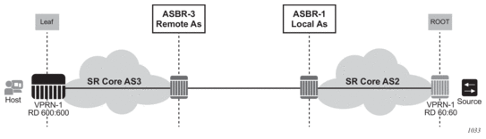
While ASBRs can also act as a PE node, SR OS does not support all PE functionalities in the ASBR node. Table 34 lists supported PE features on local and remote ASBRs.
Table 34: PE Features on Local and Remote ASBRs
Local AS ASBR Node | Remote AS ASBR Node | |||
Inter-AS Multicast Context | Leaf or Bud | Root or Source | Leaf or Bud | Root or Source |
GRT | ✓ | X | ✓ | X |
VPN | ✓ | X | ✓ | X |
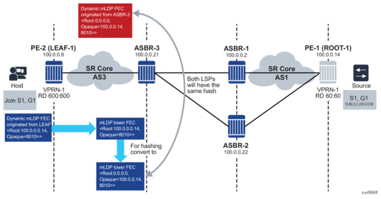
7.4. Hashing for Inter-AS
Figure 8: Hashing for Inter-AS
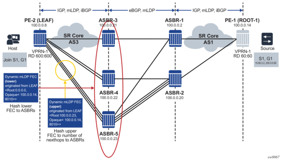
7.5. Hashing at the ASBR
Figure 9: Hashing at the ASBR