4.7. Configuring Static Label Routes using MPLS Forwarding Policy
4.7.1. Steering Flows to an Indirect Next-Hop
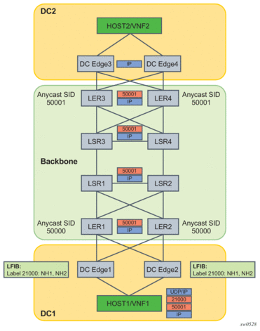
Figure 54 illustrates the traffic forwarding from a Virtual Network Function (VNF1) residing in a host in a Data Center (DC1) to VNF2 residing in a host in DC2 over the segment routing capable backbone network. DC1 and DC2 do not support segment routing and MPLS while the DC Edge routers do not support segment routing. Hence, MPLS packets of VNF1 flows are tunneled over a UDP/IP or GRE/IP tunnel and a static label route (SLR) is configured on DC Edge1/2 to steer the decapsulated packets to the remote DC Edge3/4.
Figure 54: Traffic Steering to an Indirect Next-hop using a Static Label Route

The following are the data path manipulations of a packet across this network:
- Host in DC1 pushes MPLS-over-UDP (or MPLS-over-GRE) header with outer IP destination address matching its local DC Edge1/2. It also pushes a static label 21000 which corresponds to the binding label of the static label route configured in DC Edge1/2 to reach remote DC Edge3/4 (anycast address). The bottom of the label stack is the anycast SID for the remote LER3/4.
- The label 21000 is configured on both DC Edge1 and DC Edge2 using a label-binding policy with an indirect next-hop pointing to the static route to the destination prefix of DC Edge3/4. The backup next-hop will point to the static route to reach some DC Edge5/6 in another remote DC (not shown).
- There is eBGP peering between DC Edge1/2 and LER1/2 and between DC Edge3/4 and LER3/4.
- DC Edge1/2 removes the UDP/IP header (or GRE/IP header) and swaps label 21000 to implicit-null and forwards (ECMP spraying) to all resolved next-hops of the static route of the primary or backup next-hop of the label-binding policy.
- LER1/2 forwards based on the anycast SID to remote LER3/4.
- LER3/4 removes the anycast SID label and forwards the inner IP packet to DC Edge3/4 which will then forward to Host2 in DC2.
The following CLI commands configure the static label route to achieve this use case. It creates a label-binding policy with a single NHG that is pointing to the first route as its primary indirect next-hop and the second route as its backup indirect next-hop. The primary static route corresponds to a prefix of remote DC Edge3/4 router and the backup static route to the prefix of a pair of edge routers in a different remote DC. The policy is applied to routers DC Edge1/2 in DC1.
4.7.2. Steering Flows to a Direct Next-Hop
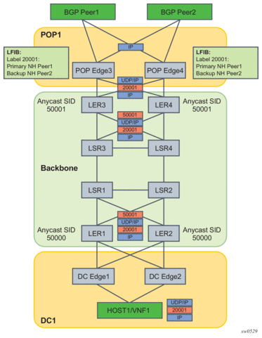
Figure 55 illustrates the traffic forwarding from a Virtual Network Function (VNF1) residing in a host in a Data Centre (DC1) to outside of the customer network via the remote peering Point Of Presence (POP1).
The traffic is forwarded over a segment routing capable backbone. DC1 and POP1 do not support segment routing and MPLS while the DC Edge routers do not support segment routing. Hence, MPLS packets of VNF1 flows are tunneled over a UDP/IP or GRE/IP tunnel and a static label route is configured on POP Edge3/4 to steer the decapsulated packets to the desired external BGP peer.
Figure 55: Traffic Steering to a Direct Next-hop using a Static Label Route

The intent is to override the BGP routing table at the peering routers (POP Edge3 and Edge4) and force packets of a flow originated in VNF1 to exit the network using a primary external BGP peer Peer1 and a backup external BGP peer Peer2, if Peer1 is down. This application is also referred to as Egress Peer Engineering (EPE).
The following are the data path manipulations of a packet across this network:
- DC Edge1/2 receives a MPLS-over-UDP (or a MPLS-over-GRE) encapsulated packet from the host in the DC with the outer IP destination address set to the remote POP Edge3/4 routers in peering POP1 (anycast address). The host also pushes the static label 20001 for the remote external BGP Peer1 it wants to send to.
- This label 20001 is configured on POP Edge3/4 using the static label route feature with primary next-hop of Peer1 and backup next-hop of Peer2.
- There is eBGP peering between DC Edge1/2 and LER1/2, and between POP Edge3/4 and LER3/4, and between POP Edge3/4 and Peer1/2.
- LER1/LER2 pushes the anycast SID of remote LER3/4 as part of the BGP route resolution to a SR-ISIS tunnel or SR-TE policy.
- LER3/4 removes the anycast SID and forwards the GRE packet to POP Edge3/4.
- POP Edge3/4 removes UDP/IP (or GRE/IP) header and swaps the static label 20001 to implicit null and forwards to Peer1 (primary next-hop) or to Peer2 (backup next-hop).
The following CLI commands configure the static label route to achieve this use case. It creates a label-binding policy with a single NHG containing a primary and backup direct next-hops and is applied to peering routers POP Edge3/4.