6.4. Configuring Video Service Components with CLI
This section provides information to configure RET/FCC using the command line interface.
6.4.1. Video Services Overview
There can be a maximum of eight ISA-MSs in a given system. The main entities of video configurations are:
- Video group
- Multicast information policy
- A video policy to configure video interface properties
- Multicast bundles and channels to associate bundles/channels with video groups
- Within a service, configuring a video interfaces and their associations with video groups.
Figure 53 shows various configuration elements and how they are associated by configuration.
Figure 53: Video Services Configuration Elements
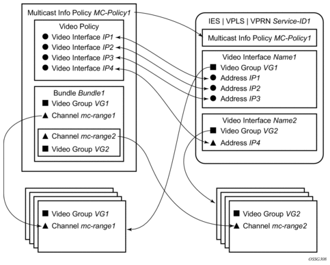
A video interface within a service can have multiple IP address, and their association with the video interfaces within the video policy are based on IP addresses. Support for multiple video interface IP addresses for a given video interface allows video characteristics (burst rate, retransmission format, etc.) for the channels associated with the video interface to be based on the IP address on which the request is received.
Both the bundle/channel configuration and the video interface configuration within the service are associated with a specific video group. If the request is received on a video interface for a channel not serviced by the video group associated with the video interface, the request is invalid and is dropped. Figure 53 displays an example of this is a request for mc-range2 received on IP1, IP2 or IP3. A request for mc-range2 would only be valid on IP4.
As with other multicast information policies, the bundle name default is a special bundle and is reserved for setting of default values. If a video parameter is not explicitly set in a bundle/channel, the value set in the default bundle is used.
6.4.1.1. Configuring an ISA-MS Module
The ISA-MS hardware has an MDA form factor and is provisioned in the same manner as other MDAs in the config>card>mda>mda-type context.
Use the following commands to configure a ISA-MS module.
The following output displays an ISA-MS configuration example:
6.4.1.2. Configuring a Video Group
When used for video services, ISA-MSes are logically grouped into video groups that pool the ISA buffering and processing resources into a single logical entity.
Use the following commands to configure a video group.
The example shown below shows video-group 1 with a single ISA configured in slot 2/MDA 1.
Within the video group configuration, there are specific video application commands to enable features. These commands are described in the configuration examples for the application. Depending on the video application, more than one primary ISA-MS is allowed increasing the egress capacity of the video group.
ISA-MS in a single video group cannot be on the same IOM. An IOM can accommodate two ISA-MS modules provided that the ISA-MS are members of different video groups.
6.4.1.3. Configuring a Video SAP and Video Interface in a Service
Video features in a VPLS service require the creation of a video SAP and a video interface. A video SAP is similar to other SAPs in the system in that QoS and filter policies can be associated with the SAP on ingress (traffic leaving the ISA and ingressing the system) and egress (traffic leaving system and entering the ISA).
The video SAP is associated with a video group. Channels are also associated with a video group which is what establishes the link between what channels can be referenced through the video SAP. The multicast information policy associated with the service is where the channel to video group association is defined.
For unicast VPLS services that have an associated multicast service that is cross connected downstream of the router, the multicast service needs to be identified by the service ID in the unicast VPLS service.
The video commands for are identical in the IES and VPRN service contexts. The basic IES and VPRN commands are similar to the video commands in the VPLS context and follow the same logic of associating the video SAP with a video group and the multicast information policy defining the channel to video group association.
Another parameter defined for a channel in the multicast information policy that is important for video services is the administrative bandwidth defined for the channel. Many video applications use the bandwidth to determine if sufficient ISA egress bandwidth exists to service or drop a service request.
The following output displays an example video interface configuration.
6.4.1.4. Basic Multicast Information Policy Configuration
Multicast information policies are used by the video applications to define multicast channel attributes and video policies which contains application-specific configuration for a video interface IP address.
It is within the multicast information policy bundles, channels and source-overrides that a video group is assigned to a channel. The video group association is inherited from the more general construct unless it is explicitly disabled.
The administrative bandwidth for channels at the bundle, channel or source-override level is also defined in the multicast information policy. Video applications use the administrative bandwidth here when a channel rate estimate is needed.
A video policy is defined within the multicast information policy for a specific video interface IP address. The IP address for the video policy is the key value that associates it with a specific video interface IP address within a service associated with overall multicast information policy.
Refer to the 7450 ESS, 7750 SR, and VSR Triple Play Service Delivery Architecture Guide for CLI command descriptions and syntax usage information to configure multicast info policies.
The following output displays a policy example.
6.4.2. Sample Configurations
The following output displays configurations of VQM with packet selection.
The following output displays configurations of VQM without packet selection.
6.5. Configuring RET/FCC Video Components with CLI
This section provides information to configure RET/FCC using the command line interface.
6.5.1. Configuring RET/FCC Video Features in the CLI
The following sections provide configuration examples for the RET client, RET server and FCC server.
6.5.1.1. Configuring the RET Client
This section provides an example configuration for the RET client. The configuration example has the following assumptions:
- A single ISA-MS in slot 2/1 in video group 1
- A single channel 192.0.2.1 within multicast bundle “b1” with an administrative bandwidth of 2700 kb/s defined in multicast-info-policy multicastinfopolicyname.
- The upstream RET server for the channel is 10.4.4.4 on UDP port 4096
- A single video interface named “v1” in the service with IP address 10.3.3.3/24
- A RET client address of 10.3.3.4 for a VPLS and 10.3.3.3 for IES and VPRN case.
The first step in the configuration is to configure video group 1 and the ISA-MS hardware.
The channel parameters for 192.0.2.1 are configured in multicast-info-policy multicastinfopolicyname. The channel configuration includes the administrative bandwidth, the channel’s association with video group 1 and the upstream RET server configuration for the channel (10.4.4.4 UDP port 4096). The following output displays the configuration. Refer to the CLI tree for a complete list of CLI commands.
The channel parameters are actually defined for the channel bundle “b1” and the channel inherits those values based on the multicast information policy inheritance rules.
For the RET client in a VPLS, the following commands within the service instance perform the following tasks to complete the RET client configuration:
- Associate the VPLS with multicast-info-policy multicastinfopolicyname.
- Create the video interface “vi”.
- Create video SAP and associate it with video group 1.
- Assigns a RET client address and gateway.
- Create a static IGMP join on SAP 3/2/13:21 for the channel 192.0.2.1.

Note: SAP 3/2/13:21 is a dummy SAP with the only purpose of attracting multicast traffic to the node to enable the caching. No subscribers are connected to it.
| Note: The RET client address is 10.3.3.4 which must be within the IP subnet assigned to the video interface (10.3.3.3/24). |
For the RET client in an IES or VPRN, the following commands within the service instance perform these tasks to complete the RET client configuration:
- Associate the service with multicast-info-policy multicastinfopolicyname.
- Create the video interface “vi” and assign IP address 10.3.3.3.
- Create video SAP and associate it with video group 1.
- Creates a static IGMP join on the video interface for the channel 192.0.2.1. (7750 SR only)
The RET client address is 10.3.3.3 which is the address assigned to the video interface in the video policy portion of the multicast information policy.
6.5.1.2. Configuring the RET Server
This section provides an example configuration for the RET server. The configuration example has the following assumptions:
- A single ISA-MS in slot 2/1 in video group 1
- A single channel 192.0.2.1 within multicast bundle “b1” with an administrative bandwidth of 2700 kb/s defined in multicast-info-policy multicastinfopolicyname.
- A retransmission buffer for the channel set to 300 milliseconds.
- The RET rate is 5% of nominal.
- Local RET server address is 10.3.3.3 with destination port is UDP 4096.
The first step in the configuration is to configure video group 1 enabling the RET server and the ISA-MS hardware.
The local-rt-server command in the above output enables the local RET server on the video group.
The channel parameters for 192.0.2.1 are configured in multicast-info-policy multicastinfopolicyname. The channel configuration includes the administrative bandwidth and the channel’s association with video group 1.
The local-rt-port command in the bundle “default” defines the destination UDP port used to reach the local RET server on the service where the multicast information policy is applied. The RET server port can only be defined in the bundle “default” and applies for all bundles in the policy. If no value is specified, the default is used.
In the bundle “b1” the local-rt-server command enables the RET server for all channels in the bundle, and the rt-buffer-size rt-buffer-size command sets the retransmission buffer for all channels in the bundle to 300 milliseconds.
In the video policy above, the local-rt-server commands for the video interface 10.3.3.3 enables the RET server on that interface for all channel types “hd” (High Definition), “sd” (Standard Definition) and “pip” (Picture-in-Picture). The rt-rate rt-burst-percentage command in the policy indicates that the retransmission rate will be 5% of the nominal rate for all channel types; individual rates can be defined if desired.
For the RET server in a VPLS, these commands within the service instance perform the following tasks to complete the RET server configuration:
- Associate the VPLS with multicast-info-policy multicastinfopolicyname.
- Create the video interface “vi”.
- Create video SAP and associate it with video group 1.
- Assigns an IP address 10.3.3.3 to the video interface.
- Create a static IGMP join on SAP 3/2/13:21 for the channel 192.0.2.1.
Note: SAP 3/2/13:21 is a dummy SAP with the only purpose of attracting multicast traffic to the node to enable the caching. No subscribers are connected to it.
The services available on the video interface address 10.3.3.3 are defined in the video policy in which the RET server was enabled.
For the RET server in an IES or VPRN, these commands within the service instance perform the following tasks to complete the RET server configuration:
- Associate the service with multicast-info-policy multicastinfopolicyname.
- Create the video interface “vi” and assign IP address 10.3.3.3.
- Create video SAP and associate it with video group 1.
- Creates a static IGMP join on video-interface “vi” for the channel 192.0.2.1.
The services available on the video interface address 10.3.3.3 are defined in the video policy in which the RET server was enabled.
6.5.1.3. Configuring the FCC Server
This section provides an example configuration for the FCC server. The configuration example has the following assumptions:
- A single ISA-MS in slot 2/1 in video group 1.
- A single channel 192.0.2.1 within multicast bundle “b1” with an administrative bandwidth of 8000 kb/s defined in multicast-info-policy multicastinfopolicyname.
- The FCC mode is burst with a rate 130% of nominal for HD, 200% for SD, and disabled for PIP.
- Local FCC server address is 10.3.3.3 with destination port is UDP 4098.
The first step in the configuration is to configure video group 1 enabling the RET server and the ISA-MS hardware.
The fcc-server command in the above output enables the FCC server on the video group.
The channel parameters for 192.0.2.1 are configured in multicast-info-policy multicastinfopolicyname. The channel configuration includes the administrative bandwidth and the channel’s association with video group 1.
The local-fcc-port command in the bundle “default” defines the destination UDP port used to reach the FCC server on the service where the multicast information policy is applied. The FCC server port can only be defined in the bundle “default” and applies for all bundles in the policy. If no value is specified, the default is used.
In the bundle “b1”, the fcc-server command enables the FCC server for all channels in the bundle, and the fcc-channel-type hd command sets the channel type for all channels in the bundle to “hd” (High Definition).
In the video policy context above, the fcc-server commands for the video interface 10.3.3.3 enables the FCC server on that interface for all channel types “hd” (High Definition), “sd” (Standard Definition) whereas the no fcc-server command disables the FCC for “pip” (Picture-in-Picture) channels on the video interface. The fcc-burst command in the policy indicates that the burst rate over the nominal rate for the channel type; HD at 130% (30% over nominal) and SD at 200% (100% over nominal).
For the FCC server in a VPLS, the following commands within the service instance perform the following tasks to complete the FCC server configuration:
- Associate the VPLS with multicast-info-policy multicastinfopolicyname.
- Create the video interface “vi”.
- Create video SAP and associate it with video group 1.
- Assigns an IP address 10.3.3.3 to the video interface.
- Create a static IGMP join on SAP 3/2/13:21 for the channel 192.0.2.1.
Note: SAP 3/2/13:21 is a dummy SAP with the only purpose of attracting multicast traffic to the node to enable the caching. No subscribers are connected to it.
The services available on the video interface address 10.3.3.3 are defined in the video policy in which the FCC server was enabled.
For the FCC server in an IES or VPRN, the following commands within the service instance perform the following tasks to complete the FCC server configuration:
- Associate the service with multicast-info-policy multicastinfopolicyname.
- Create the video interface “vi” and assign IP address 10.3.3.3.
- Create video SAP and associate it with video group 1.
- Creates a static IGMP join on video-interface “vi” for the channel 192.0.2.1.
The services available on the video interface address 10.3.3.3 are defined in the video policy in which the FCC server was enabled.
6.5.1.4. Logging and Accounting Collection for Video Statistics
The following output displays a configuration example used in logging and accounting for video.
Use the following CLI to enable logging and accounting to a service to collect stats for that particular service.
Example:
Starting stats collection can be enabled by executing a no shutdown command on the accounting policy. This starts the recording of stats and the stats will be written in an act-collect directory and a shutdown command on the accounting policy will move the recorded file to act directory.
6.6. Configuring ADI Components with CLI
This section provides information to configure ADI using the command line interface.
6.6.1. Configuring ADI in CLI
6.6.1.1. Configuring the RET Client
This section provides an example configuration for the ADI splicer. The configuration example makes the following assumptions:
- A single ISA-MS is configured in slot 2/1 in video group 1.
- The NTP server for the router is 192.168.15.221.
- A single channel main 192.0.2.140 within multicast bundle “b1” is defined in the multicast-info-policy multicastinfopolicyname context.
- IES service 100 is a Layer 3 service in which ADI will be performed.
- The video interface in IES 100 is 10.100.0.254/8
- The ad server address is 10.200.14.2
- The splicer’s local addresses used to communicate with the ad server are 10.1.1.2 for control traffic and 10.1.1.3 for data traffic.
- For the SCTE 30 communication in the example, the main channel is named 228 with (S,G) = (192.168.9.10,234.4.5.228) and the zone channel is named 228-1with (S,G) = (10.100.100.1,234.4.5.228).
- Must have an IGMP static entry for the network channel (S,G) on the video-interface to attract the network traffic to the video interface.
- Must have the video-interface enabled in PIM.
6.6.1.2. Configuring a Video Group
The first step in the configuration is to configure a video group (video-group-id = 1) and enabling ad insertion and the ISA-MS hardware. The ad-insert command enables the ADI splicer on the video group.
The following output shows the card and MDA configuration.
6.6.1.3. Configuring NTP
NTP is required on the splicer to ensure that time is synchronized between it and the ad server.
6.6.1.4. Configuring Channel Parameters
The channel parameters for 192.0.2.228 are configured in the multicast-info-policy multicastinfopolicyname context. For ADI, the channel configuration required is the channel’s association with video group 1.
6.6.1.5. Configuring Service Entities
In addition to the commands needed to configure a service, the following commands within the service instance are used to perform the following ADI configuration steps. This example uses an IES service context.
- Associate IES 100 with multicast-info-policy multicastinfopolicyname.
- Create the video interface video-100.
- Create a video SAP and associate it with video group 1.
- Assigns an IP address 10.100.0.254 to the video interface and subnet 10.0.0.0/8.
- Name the main channel (S,G) = (192.168.9.10,234.4.5.228) “228” and the zone channel (S,G) = (10.100.100.1,234.4.5.228) “228-1”.
- Configure the ad server (address = 10.200.14.2) and create IP addresses within the video interface subnet for SCTE 30 control traffic (10.1.1.2) and data traffic (10.1.1.3).
- The control and data addresses must be in the video interface subnet.
The source address (10.100.100.1) for the zone channel (S,G) and the local addresses (10.1.1.2 and 10.1.1.3) used for SCTE 30 communication must all be within the video interface subnet (10.0.0.0/8).
Connections are accepted from multiple ad-servers. This can be used for ad server redundancy.
If the main channel were a (*,G), the source address of 0.0.0.0 would have been specified.
Additional zone channels with distinct names could be configured within the service instance. In a practical configuration, the G for the main channel (192.0.2.228) will be the same for G in the zone channel (S,G) because the STBs will join the (*,G) at the A-server and D-server.
Configuring ADI for a VPRN service instance uses the same commands within the VPRN service context.