2. Services Overview
2.1. Introduction
A service is a globally unique entity that refers to a type of connectivity service for either Internet or VPN connectivity. Each service is uniquely identified by a service ID and an optional service name within a service area. The Nokia service router model uses logical service entities to construct a service. In the service model, logical service entities provide a uniform, service-centric configuration, management, and billing model for service provisioning.
In the Nokia router services can provide Layer 2 bridged service or Layer 3 IP-routed connectivity between a service access point (SAP) on one router and another service access point (a SAP is where traffic enters and exits the service) on the same (local) router or another router (distributed). A distributed service spans more than one router.
Distributed services use service distribution points (SDPs) to direct traffic to another Nokia router through a service tunnel. SDPs are created on each participating router, specifying the origination address (the router participating in the service communication) and the destination address of another router. SDPs are then bound to a specific customer service. Without the binding process, far-end router is not able to participate in the service (there is no service without associating an SDP with a service).
2.1.1. Service Types
The Nokia routers offer the following types of subscriber services which are described in more detail in the referenced chapters:
- Virtual Leased Line (VLL) services:
- Ethernet pipe (Epipe) — A Layer 2 point-to-point VLL service for Ethernet frames.
- ATM VLL (Apipe) — A 7750 SR point-to-point ATM service between users connected to 7750 SR nodes on an IP/MPLS network.
- Frame-Relay (Fpipe) — A7750 SR point-to-point Frame Relay service between users connected to 7750 SR nodes on the IP/MPLS network.
- IP Pipe (Ipipe) — Provides 7750 SR and 7450 ESS IP connectivity between a host attached to a point-to-point access circuit (FR, ATM, PPP) with routed IPv4 encapsulation and a host attached to an Ethernet interface.
Refer to the 7450 ESS, 7750 SR, 7950 XRS, and VSR Layer 2 Services and EVPN Guide: VLL, VPLS, PBB, and EVPN for more information about VLL services. - Virtual Private LAN Service (VPLS) — A Layer 2 multipoint-to-multipoint VPN. VPLS includes Hierarchical VPLS (H-VPLS) which is an enhancement of VPLS which extends Martini-style signaled or static virtual circuit labeling outside the fully meshed VPLS core.Refer to the 7450 ESS, 7750 SR, 7950 XRS, and VSR Layer 2 Services and EVPN Guide: VLL, VPLS, PBB, and EVPN for more information about VPLS.
- Internet Enhanced Service (IES) — A direct Internet access service where the customer is assigned an IP interface for Internet connectivity.Refer to the 7450 ESS, 7750 SR, 7950 XRS, and VSR Layer 3 Services Guide: IES and VPRN for more information about IES.
- Virtual Private Routed Network (VPRN) — A Layer 3 IP multipoint-to-multipoint VPN service as defined in RFC 2547bis.Refer to the 7450 ESS, 7750 SR, 7950 XRS, and VSR Layer 3 Services Guide: IES and VPRN for more information about VPRN services.
- Circuit Emulation Service (Cpipe) — 7750 SR circuits encapsulated in MPLS use circuit pipes (Cpipes) to connect to the far end circuit. Cpipes support either SAP-spoke SDP or SAP-SAP connections.
2.1.2. Service Policies
Common to all Nokia service router connectivity services are policies that are assigned to the service. Policies are defined at a global level and then applied to a service on the router. Policies are used to define Nokia service router service enhancements. The types of policies that are common to the router’s connectivity services are:
- SAP Quality of Service (QoS) policies which allow for different classes of traffic within a service at SAP ingress and SAP egress.QoS ingress and egress policies determine the QoS characteristics for a SAP. A QoS policy applied to a SAP specifies the number of queues, queue characteristics (such as forwarding class, committed, and peak information rates, and so on) and the mapping of traffic to a forwarding class. A QoS policy must be created before it can be applied to a SAP. A single ingress and a single egress QoS policy can be associated with a SAP.
- Filter policies allow selective blocking of traffic matching criteria from ingressing or egressing a SAP.Filter policies, also referred to as access control lists (ACLs), control the traffic allowed in or out of a SAP based on MAC or IP match criteria. Associating a filter policy on a SAP is optional. Filter policies are identified by a unique filter policy ID. A filter policy must be created before it can be applied to a SAP. A single ingress and single egress filter policy can be associated with a SAP.
- Scheduler policies define the hierarchy and operating parameters for virtual schedulers. Schedulers are divided into groups based on the tier each scheduler is created under. A tier is used to give structure to the schedulers within a policy and define rules for parent scheduler associations.
- Accounting policies define how to count the traffic usage for a service for billing purposes.The routers provide a comprehensive set of service-related counters. Accounting data can be collected on a per-service, per-forwarding class basis, which enables network operators to accurately measure network usage and bill each customer for each individual service using any of a number of different billing models.
2.1.2.1. Multipoint Shared Queuing
Multipoint shared queuing is supported only on Nokia service router routers.
Multipoint shared queuing is supported to minimize the number of multipoint queues created for ingress VPLS, IES or VPRN SAPs or ingress subscriber SLA profiles. Normally, ingress multipoint packets are handled by multipoint queues created for each SAP or subscriber SLA profile instance. In some instances, the number of SAPs or SLA profile instances are sufficient for the in use multipoint queues to represent many thousands of queues on an ingress forwarding plane. If multipoint shared queuing is enabled for the SAPs or SLA profile instances on the forwarding plane, the multipoint queues are not created. Instead, the ingress multipoint packets are handled by the unicast queue mapped to the forwarding class of the multipoint packet.
Functionally, multipoint shared queuing is a superset of shared queuing. With shared queuing on a SAP or SLA profile instance, only unicast packets are processed twice, once for the initial service level queuing and a second time for switch fabric destination queuing. Shared queuing does not affect multipoint packet handling. Multipoint packet handling in normal (service queuing) is the same as shared queuing. When multipoint shared queuing is enabled, shared queuing for unicast packets is automatically enabled.
2.1.2.1.1. Ingress Queuing Modes of Operation
Three modes of ingress SAP queuing are supported for multipoint services (IES, VPLS and VPRN); service, shared, and multipoint shared. The same ingress queuing options are available for IES and VPLS subscriber SLA profile instance queuing.
2.1.2.1.2. Ingress Service Queuing
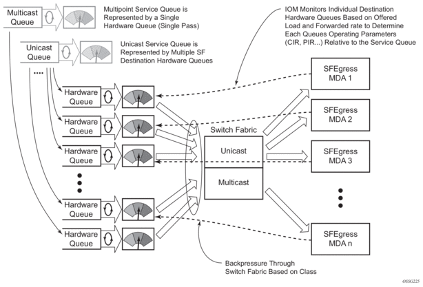
Normal or service queuing is the default mode of operation for SAP ingress queuing. Service queuing preserves ingress forwarding bandwidth by allowing a service queue defined in an ingress SAP QoS policy to be represented by a group of hardware queues. A hardware queue is created for each switch fabric destination to which the logical service queue must forward packets. For a VPLS SAP with two ingress unicast service queues, two hardware queues are used for each destination forwarding engine the VPLS SAP is forwarding to. If three switch fabric destinations are involved, six queues are allocated (two unicast service queues multiplied by three destination forwarding complexes equals six hardware queues). Figure 1 demonstrates unicast hardware queue expansion. Service multipoint queues in the ingress SAP QoS policy are not expanded to multiple hardware queues, each service multipoint queue defined on the SAP equates to a single hardware queue to the switch fabric.
When multiple hardware queues represent a single logical service queue, the system automatically monitors the offered load and forwarding rate of each hardware queue. Based on the monitored state of each hardware queue, the system imposes an individual CIR and PIR rate for each queue that provides an overall aggregate CIR and PIR reflective of what is provisioned on the service queue.
Figure 1: Unicast Service Queue Mapping to Multiple Destination Based Hardware Queues
2.1.2.1.3. Ingress Shared Queuing
To avoid the hardware queue expansion issues associated with normal service based queuing, the system allows an ingress logical service queue to map to a single hardware queue when shared queuing is enabled. Shared queuing uses two passes through the ingress forwarding plane to separate ingress per service queuing from the destination switch fabric queuing. In the case of shared queuing, ingress unicast service queues are created one-for-one relative to hardware queues. Each hardware queue representing a service queue is mapped to a special destination in the traffic manager that ‘forwards’ the packet back to the ingress forwarding plane allowing a second pass through the traffic manager. In the second pass, the packet is placed into a ‘shared’ queue for the destination forwarding plane. The shared queues are used by all services configured for shared queuing.
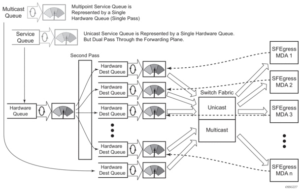
When the first SAP or SLA profile instance is configured for shared queuing on an ingress forwarding plane, the system allocates eight hardware queues per available destination forwarding plane, one queue per forwarding class. Twenty four hardware queues are also allocated for multipoint shared traffic. The shared queue parameters that define the relative operation of the forwarding class queues are derived from the Shared Queue policy defined in the QoS CLI node. Figure 2 demonstrates shared unicast queuing. SAP or SLA profile instance multipoint queuing is not affected by enabling shared queuing. Multipoint queues are still created as defined in the ingress SAP QoS policy and ingress multipoint packets only traverse the ingress forwarding plane a single time, as demonstrated in Figure 3.
Enabling shared queuing may affect ingress performance due to double packet processing through the service and shared queues.
Figure 2: Unicast Service Queuing With Shared Queuing Enabled
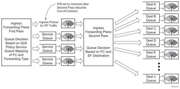
Figure 3: Multipoint Queue Behavior with Shared Queuing Enabled
2.1.2.1.4. Ingress Multipoint Shared Queuing
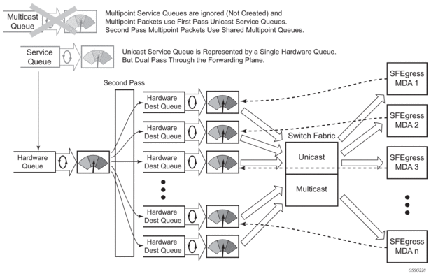
Ingress multipoint shared queuing is a variation to the unicast shared queuing defined in Ingress Shared Queuing. Ingress unicast service queues are mapped one-for-one with hardware queues and unicast packets traverse the ingress forwarding plane twice. In addition to the above, the multipoint queues defined in the ingress SAP QoS policy are not created. Instead, multipoint packets (broadcast, multicast and unknown unicast destined) are treated to the same dual pass ingress forwarding plane processing as unicast packets. In the first pass, the forwarding plane uses the unicast queue mappings for each forwarding plane. The second pass uses the multipoint shared queues to forward the packet to the switch fabric for special replication to all egress forwarding planes that need to process the packet.
The benefit of defining multipoint shared queuing is the savings of the multipoint queues per service. By using the unicast queues in the first pass and then the aggregate shared queues in the second pass, per service multipoint queues are not required. The predominate scenario where multipoint shared queuing may be required is with subscriber managed QoS environments using a subscriber per SAP model. Usually, ingress multipoint traffic is minimal per subscriber and the extra multipoint queues for each subscriber reduces the overall subscriber density on the ingress forwarding plane. Multipoint shared queuing eliminates the multipoint queues sparing hardware queues for better subscriber density. Figure 4 demonstrates multipoint shared queuing.
One disadvantage of enabling multipoint shared queuing is that multipoint packets are no longer managed per service (although the unicast forwarding queues may provide limited benefit in this area). Multipoint packets in a multipoint service (VPLS, IES and VPRN) use significant resources in the system, consuming ingress forwarding plane multicast bandwidth and egress replication bandwidth. Usually, the per service unicast forwarding queues are not rate limited to a degree that allows adequate management of multipoint packets traversing them when multipoint shared queuing is enabled. It is possible to minimize the amount of aggregate multipoint bandwidth by setting restrictions on the multipoint queue parameters in the QoS node’s shared queue policy. Aggregate multipoint traffic can be managed per forwarding class for each of the three forwarding types (broadcast, multicast or unknown unicast – broadcast and unknown unicast are only used by VPLS).
A second disadvantage to multipoint shared queuing is the fact that multipoint traffic now consumes double the ingress forwarding plane bandwidth due to dual pass ingress processing.
Figure 4: Multipoint Shared Queuing Using First Pass Unicast Queues
2.2. Nokia Service Model
In the Nokia service model, the service edge routers are deployed at the provider edge. Services are provisioned on the service routers and transported across an IP and/or IP/MPLS provider core network in encapsulation tunnels created using generic router encapsulation (GRE) or MPLS label switched paths (LSPs).
The service model uses logical service entities to construct a service. The logical service entities are designed to provide a uniform, service-centric configuration, management, and billing model for service provisioning. Some benefits of this service-centric design include:
- Many services can be bound to a single customer.
- Many services can be bound to a single tunnel.
- Tunnel configurations are independent of the services they carry.
- Changes are made to a single logical entity rather than multiple ports on multiple devices. It is easier to change one tunnel rather than several services.
- The operational integrity of a logical entity (such as a service tunnel and service end points) can be verified rather than dozens of individual services improving management scaling and performance.
- On 7450 ESS and 7750 SR OS, a failure in the network core can be correlated to specific subscribers and services.
- QoS policies, filter policies, and accounting policies are applied to each service instead of correlating parameters and statistics from ports to customers to services.
Service provisioning uses logical entities to provision a service where additional properties can be configured for bandwidth provisioning, QoS, security filtering, accounting/billing to the appropriate entity.
2.3. Service Entities
The basic logical entities in the service model used to construct a service are:
- Service Distribution Points (for distributed services only)
Figure 5: Service Entities
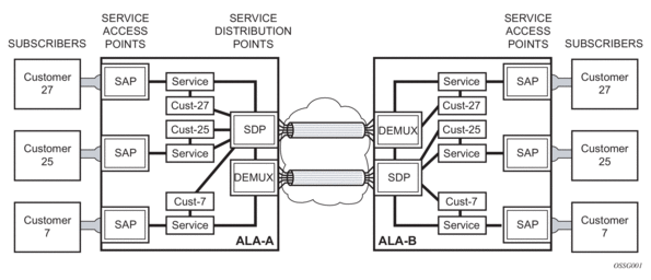
2.3.1. Customers
In this section, the terms customers and subscribers are used synonymously. The most basic required entity is the customer ID value which is assigned when the customer account is created. To provision a service, a customer ID must be associated with the service at the time of service creation.
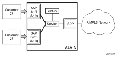
2.3.2. Service Access Points (SAPs)
Each subscriber service type is configured with at least one service access point (SAP). A SAP identifies the customer interface point for a service on a router (for example Figure 6). The SAP configuration requires that slot, XMA or MDA, and port/channel information be specified. The slot, XMA or MDA, and port/channel parameters must be configured prior to provisioning a service (Refer to the XMAs, Cards, MDAs, and Ports sections of the SR OS Interface Configuration Guide).
A SAP is a local entity to the router and is uniquely identified by:
- The physical Ethernet port or SONET/SDH port or TDM channel
- The encapsulation type
- The encapsulation identifier (ID)
Depending on the encapsulation, a physical port or channel can have more than one SAP associated with it. SAPs can only be created on ports or channels designated as “access” in the physical port configuration. SAPs cannot be created on ports designated as core-facing “network” ports as these ports have a different set of features enabled in software.
Figure 6: 7750 SR/7950 XRS Service Access Point (SAP)
A SAP can also be associated with a pseudowire port rather than an access port. Such SAPs are called pseudowire SAPs. This is only applicable to IES, VPRN, and Epipe services. Pseudowire ports represent pseudowires in enhanced subscriber management (ESM). For a description of pseudowire ports, see the 7450 ESS, 7750 SR, and VSR Triple Play Service Delivery Architecture Guide.
2.3.2.1. SAP Encapsulation Types and Identifiers
The encapsulation type is an access property of a service Ethernet port or SONET/SDH or TDM channel. The appropriate encapsulation type for the port or channel depends on the requirements to support multiple services on a single port or channel on the associated SAP and the capabilities of the downstream equipment connected to the port or channel. For example, a port can be tagged with IEEE 802.1Q (referred to as dot1q) encapsulation in which each individual tag can be identified with a service. A SAP is created on a given port or channel by identifying the service with a specific encapsulation ID.
2.3.2.2. Ethernet Encapsulations
The following lists encapsulation service options on Ethernet ports:
- Null — Supports a single service on the port. For example, where a single customer with a single service customer edge (CE) device is attached to the port. The encapsulation ID is always 0 (zero).
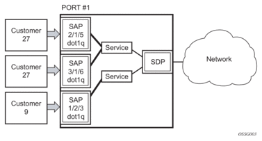
- Dot1q — Supports multiple services for one customer or services for multiple customers (Figure 6 and Figure 7). For example, the port is connected to a multi-tenant unit (MTU) device with multiple downstream customers. The encapsulation ID used to distinguish an individual service is the VLAN ID in the IEEE 802.1Q header.
- QinQ — The QinQ encapsulation type adds a IEEE 802.1Q tag to the 802.1Q tagged packets entering the network to expand the VLAN space by tagging tagged packets, producing a double tagged frame.
There are several 7750 SR encapsulation service options on SONET/SDH channels:
- Internet Protocol Control Protocol (IPCP) — Supports a single IP service on a SONET/SDH port or a single service per channel (if the interface is channelized). This is typically used for router interconnection using point-to-point protocol (PPP).
- Bridging Control Protocol (BCP-null) — Supports a single service on the SONET/SDH port or a single service per channel (if the interface is channelized). This is used for bridging a single service between two devices using PPP over SONET/SDH. The encapsulation ID is always 0 (zero).
- Bridging Control Protocol (BCP-dot1q) — Supports multiple services on the SONET/SDH port/channel. This encapsulation type is used for bridging multiple services between two devices using PPP over SONET/SDH. The encapsulation ID used to distinguish services is the VLAN ID in the IEEE 802.1Q header in the BCP-encapsulated frame.
- ATM — ATM, ATM-FR, ATM SAP-bridge encapsulation termination Epipe and VPLS.
- Frame Relay — Supports the switched data link layer protocol that handles multiple virtual circuits.
There are several 7450 ESS encapsulation service options on SONET/SDH channels:
- Internet Protocol Control Protocol (IPCP) — Supports a single IP service on a SONET/SDH port. This is typically used for router interconnection using point-to-point protocol (PPP).
- Bridging Control Protocol (BCP-null) — Supports a single service on the SONET/SDH port. This is used for bridging a single service between two devices using PPP over SONET/SDH. The encapsulation ID is always 0 (zero).
- Bridging Control Protocol (BCP-dot1q) — Supports multiple services on the SONET/SDH port. This encapsulation type is used for bridging multiple services between two devices using PPP over SONET/SDH. The encapsulation ID used to distinguish services is the VLAN ID in the IEEE 802.1Q header in the BCP-encapsulated frame.
- Frame Relay — Supports the switched data link layer protocol that handles multiple virtual circuits.
Figure 7: 7750 SR/7950 XRS and 7450 ESS Multiple SAPs on a Single Port/Channel
2.3.2.3. Default SAP on a Dot1q Port
On dot1q-encapsulated ports where a default SAP is configured, all packets with q-tags not matching any explicitly defined SAPs will be assigned to this SAP. SAPs with default QinQ encapsulation are supported in VPLS, Epipe, IES and VPRN services. Both DHCP snooping and IGMP snooping are supported for QinQ SAPs. In this context, the character “*” indicates “default” which means “allow through”. A 0 value allows the Qtag to be missing.
One of the applications where this feature can be applicable is an access connection of a customer who uses the whole port to access Layer 2 services. The internal VLAN tags are transparent to the service provider. This can be provided by a null encapsulated port. A dedicated VLAN (not used by the user) can be used to provide CPE management.
In this type of environment, logically two SAPs exist, a management SAP and a service SAP. The management SAP can be created by specifying a VLAN tag which is reserved to manage the CPE. The service SAP covers all other VLANs and behaves as a SAP on a null-encapsulated port.
There a few constraints related for the use of default SAP on a Dot1q-encapsulated port:
- This type of SAP is supported only on VPLS and Epipe services and cannot be created in IES and VPRN services as it cannot preserve VLAN tag markings.
- For VPLS SAPs with STP enabled, STP listens to untagged and null-tagged BPDUs only. All other tagged BPDUs are forwarded like other customer packets. This is the same behavior as null-encapsulated ports.
- IGMP snooping is not supported on a default SAP. This would require remembering VLAN tags per hosts. By not allowing IGMP snooping of this SAP, all IGMP packets will be transparently forwarded.
- This type of SAP is mutually exclusive with a SAP defined by explicit null encapsulation (for example, 1/1/1:0). This avoids conflict as to which SAP untagged frames should be associated.
In a Dot1q port SAP with a non-zero or non-default tag, the tag (referred to as service-delimiting tag) is stripped off on ingress and pushed on egress. For example, the tag is popped from frames received on SAP 1/1/1:10 with a tag that contains VID 10. A tag with VID 10 will be pushed onto frames that are sent out of SAP 1/1/1:10.
In case of Dot1q port SAPs with a zero or default tag, no tag is stripped off on ingress, and no tag is pushed on egress. For instance, tags are not stripped off from frames entering 1/1/1:* or 1/1/1:0, and tags are not pushed either on frames egressing those SAPs.
2.3.2.4. QinQ SAPs
A QinQ SAP has the following format:
qinq <port-id | lag-id>:qtag1.qtag2
Where:
- qtag1 is the outer qtag value - [*, 0 to 4094]
- qtag2 is the inner qtag value - [*, null, 0 to 4094]
Regular QinQ SAPs have qtag1 and qtag2 values between 1 and 4094. In addition, QinQ Ethernet and LAG ports support the following “default” SAPs that can be enabled by the new-qinq-untagged-sap command:
- ‘*.null’ is defined as a default sap for singly-tagged frames in a QinQ port. This SAP accepts single tags in the range 0 to 4095 as well as untagged traffic. This SAP never pushes any tags on egress.
- ‘*.*’ is defined as a default sap for doubly-tagged frames in a QinQ port. This SAP accepts untagged, singly tagged, and doubly tagged frames with tags in the range 0..4095. This SAP never pushes any tags on egress.
- In addition to the above-mentioned SAPs, qtag2 can also be '0' or '*' when qtag1 is an explicit value in the 1 to 4094 range, for instance: 1/1/1:10.0 or 1/1/1:10.*. Assuming qtag1 is the same value, qtag1.* and qtag1.0 are supported in the same QinQ port. The system never pushes any qtag2 on egress for 1/1/110.0 and 1/1/1:10.*, only qtag1 is pushed. The x.0 accepts only 0 as second tag or not tag (and nothing else), while x.* accepts anything as second tag or no tag.
A SAP lookup is performed when a new frame arrives to a QinQ port. This 'lookup' is based on the <outer-tag, inner-tag> values of the frame.
Table 3 shows the SAP lookup precedence order for incoming frames with <qtag1.qtag2> qtag values.
Table 3: SAP Lookup Precedence Order for Incoming Frames
Incoming Frame qtag1.qtag2 | System/Port settings [new-qinq-untagged-sap=YES] | |||||
SAP Lookup Precedence Order | ||||||
:X.Y | :X.0 | :X.* | :0.* | :*.null | :*.* | |
x.y | 1st | 2nd | 3rd | |||
x.0 | 1st | 2nd | 3rd | |||
0.y | 1st | 2nd | ||||
0.0 | 1st | 2nd | ||||
x | 1st | 2nd | 3rd | 4th | ||
0 | 1st | 2nd | 3rd | |||
<untagged> | 1st | 2nd | 3rd | |||
The following considerations apply to the information described in Table 3:
- All six SAP types (:X.Y, :X.0, :X.*, :0.*, :*.null and :*.*) are supported in the same QinQ port and, in the table, they are ordered from the most specific (left-hand side) to the least specific with the following VID matching ranges:
- X or Y means <1 to 4094>
- * means <0 to 4095> or untagged
- null means 'no tag'
- 0 means VID 0 or untagged
- On egress, the system will push a tag with a VID value for X and Y, whereas no tag is pushed on egress for values 0, * or null. For example:
- On SAP 1/1/1:10.20, the system pushes tags with VIDs 10 and 20 (outer and inner respectively) on egress.
- On SAP 1/1/1:10.0 or 1/1/1:10.* the system pushes only one tag with VID 10 on egress.
- On SAPs 1/1/1:0.*, 1/1/1:*.null or 1/1/1:*.* the system never pushes any tags on egress.
- The user can decide the SAP types that are configured in a specific port. Not all SAP types must be configured in a port.
- Table 3 shows the lookup behavior for ingress frames and priority across SAPs in case more than one can match a given ingress frame. The SAP lookup result for a given frame does not depend on the operational status of the SAP. For instance:
- In a port with SAPs 1/1/1:0.* and 1/1/1:*.* defined, the SAP lookup for a given frame with VIDs (0, 300) will yield SAP 1/1/1:0.* regardless of its operational status.
- The frame will only match SAP 1/1/1:*.* when the 0.* SAP is removed from the configuration.
- The following apply to VLAN tag handling:
- The system will not strip-off any tags for frames entering the default SAPs (:0.*, :*.null or :*.*).
- No extra tags are added when the system transmits frames on the default SAPs (:0.*, :*.null or :*.*).
The following examples illustrate the SAP classification QinQ ports. The examples assume that the new-qinq-untagged-sap command is enabled.
Example - 1
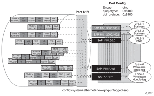
As shown in Figure 8, assuming that the new-qinq-untagged-sap command is enabled, the following SAPs are defined on the same port:
- 1/1/1:3000.1001 - business customer - vpls-1
- 1/1/1:2000.1002 - business customer - vpls-2
- 1/1/1:20.0 - BNG traffic - vpls-3
- 1/1/1:20.* - business customer - epipe-4
- 1/1/1:0.* - business customer - epipe-5
- 1/1/1:*.null - wholesaling single tag - epipe-6
- 1/1/1:*.* - wholesaling double tag - epipe-7
Figure 8: Example 1 SAP Classification QinQ Ports

Based on the SAPs configuration described above, the incoming traffic is classified in the following way - notation (outer-VID, inner-VID):
- (3000, 1001) goes to vpls-1
- (20) goes to BNG (vpls-3)
- (20, 0) goes to BNG (vpls-3)
- (20, 10) goes to epipe-4
- untagged, (0), (0, 0), and (0, 10) go to epipe-5
- (500) goes to wholesaling single tag (epipe-6)
- (500, 300) and (500, 0) go to wholesaling double tag (epipe-7)
Example - 2
Figure 9 highlights how untagged, VID=0 tagged frames and 20.X frames are classified in the absence of the 0.* and 20.* SAPs.
Figure 9: Example 2 SAP Classification QinQ Ports
As outlined in Figure 9, assuming the new-qinq-untagged-sap command is enabled, the following SAPs are defined on the same port:
- 1/1/1:3000.1001 - business customer - vpls-1
- 1/1/1:2000.1002 - business customer - vpls-2
- 1/1/1:20.0 - BNG traffic - vpls-3
- 1/1/1:*.null - wholesaling single tag - epipe-6
- 1/1/1:*.* - wholesaling double tag - epipe-7
Incoming traffic - notation (outer-VID, inner-VID)
- (3000, 1001) goes to vpls-1
- (20) goes to BNG (vpls-3)
- (20, 0) goes to BNG (vpls-3)
- (20, 10) goes to wholesaling double tag (epipe-7)
- untagged and (0) go to wholesaling single tag (epipe-6)
- (500) goes to wholesaling single tag (epipe-6)
- (500, 300) and (500, 0) go to wholesaling double tag (epipe-7)
- (0,0), and (0,10) goes to wholesaling double tag (epipe-7)
| Note: The system will not add service-delimiting tags with VID=0; however, tags with VID=0 are accepted and classified appropriately. |
The following constraints must be considered when configuring default QinQ SAPs (:0.*, :*.null, :*.*):
- Only supported in Ethernet ports or LAG.
- Only supported on Epipe, PBB-Epipe, VPLS and I-VPLS services. They are not supported on VPRN, IES, R-VPLS or B-VPLS services.
- Capture SAPs with encapsulation :*.* cannot coexist with a default :*.* SAP on the same port.
- Inverse-capture SAPs (*.x) are mutually-exclusive with :*.null SAPs.
- *.null SAPs are not supported for Open Flow matching and forwarding.
- The following applies to Eth-CFM:
- Primary VLAN is not supported.
- Eth-CFM extractions occur within the service after the packet lookup has determined which service the inbound packet belongs to.
- All three SAPs (*.null, *.* and 0.*) are treated equally by ETH-CFM. Only untagged CFM PDUs are extracted by a local MEP or MIP. Additional tags in the header may match the service context but are not extracted by ETH-CFM for processing.
- ETH-CFM PDU transmission encapsulation is based on the SAP configuration. This means that the ETH-CFM PDUs will be transmitted out all three of these SAPs untagged. Care must be taken to ensure that there is no downstream service that may intercept the ETH-CFM PDUs that are not intended for that service. See Table 3 for a description of the SAP lookup precedence order for incoming frames and to understand the potential consequences.
- Default QinQ SAPs do not support the following features:
- PW-SAPs
- Eth-tunnel or eth-ring SAPs
- VLAN-translation copy-outer
- E-Tree root-leaf-tag SAPs
- Subscriber-management features
- BPDU-translation
- Eth-tunnels
- IGMP-snooping
- MLD-snooping
2.3.2.5. Services and SAP Encapsulations
The services and SAP encapsulations are listed in Table 4.
Table 4: Service and SAP Encapsulations
Port Type | Encapsulation |
Ethernet | Null |
Ethernet | Dot1q |
Ethernet | QinQ |
SONET/SDH | IPCP |
SONET/SDH | BCP-null |
SONET/SDH | BCP-dot1q |
SONET/SDH | ATM |
SONET/SDH | Frame Relay |
SONET/SDH | Cisco HDLC |
2.3.2.6. SAP Configuration Considerations
When configuring a SAP, consider the following:
- A SAP is a local entity and only locally unique to a given device. The same SAP ID value can be used on another Nokia router.
- There are no default SAPs. All SAPs in subscriber services must be created.
- The default administrative state for a SAP at creation time is administratively enabled.
- When a SAP is deleted, all configuration parameters for the SAP will also be deleted. For Internet Enhanced Service (IES), the IP interface must be shutdown before the SAP on that interface may be removed.
- A SAP is owned by and associated with the service in which it is created in each router.
- A port or channel with a dot1q or BCP-dot1q encapsulation type means the traffic for the SAP is identified based on a specific IEEE 802.1Q VLAN ID value. The VLAN ID is stripped off at SAP ingress and the appropriate VLAN ID placed on at SAP egress. As a result, VLAN IDs only have local significance, so the VLAN IDs for the SAPs for a service need not be the same at each SAP.
- If a port or channel is administratively shutdown, all SAPs on that port or channel will be operationally out of service.
- A SAP cannot be deleted until it has been administratively disabled (shutdown).
- Each SAP can have one each of the following policies assigned:
- Ingress filter policy
- Egress filter policy
- Ingress QoS policy
- Egress QoS policy
- Accounting policy
- Ingress scheduler policy
- Egress scheduler policy
2.3.2.7. G.8032 Protected Ethernet Rings
Ethernet ring protection switching offers ITU-T G.8032 specification compliance to achieve resiliency for Ethernet Layer 2 networks. G.8032 (Ethernet-ring) is built on Ethernet OAM and often referred to as Ring Automatic Protection Switching (R-APS).
For further information on Ethernet rings, see G.8032 Ethernet Ring Protection Switching.
2.3.2.8. SAP Bandwidth CAC
This feature provides a bandwidth CAC function per port or per LAG based on an admin bandwidth configured on a SAP and on the associated port or LAG. A booking factor is provided in order to allow over/under booking of the sum of the SAP bandwidth compared to the port/LAG bandwidth.
The admin bandwidth is an abstract value which could represent either, or both, of the ingress or egress bandwidth and is statically configured.
The goal of the CAC function is to ensure that the sum of the admin SAP bandwidth on a port or LAG does not exceed the admin bandwidth configured on that port or LAG.
This is supported on all service Ethernet SAPs, excluding PW SAPs, Ethernet tunnels and subscriber group interface SAPs. It is not supported in a VPLS or Epipe SAP template. It is applicable to both access and hybrid ports or LAGs; in the case of a hybrid port or LAG, the SAP CAC bandwidth only applies to the access operation.
By default a SAP, port or LAG has no admin bandwidth configured in which case it is excluded from the CAC function. Configuring an admin bandwidth on a SAP will cause the CAC function to be enforced.
An admin bandwidth can only be configured on a SAP connected to a port or LAG which itself has an admin bandwidth configured. When a LAG is configured, the admin bandwidth and booking factor on its constituent ports are ignored.
The system tracks the requested and available bandwidth per port or LAG, where the available bandwidth is equal to the admin bandwidth on the port or LAG, with the booking factor applied, minus the sum of admin bandwidth configured on its SAPs. An attempt to increase a SAP's admin bandwidth will fail if there is insufficient available bandwidth on its port or LAG.
The admin bandwidth and booking factor for the port or LAG is configured as follows:
Changes in admin bandwidth and booking factor are possible dynamically without having to disable the SAP, port or LAG.
Once a SAP has been allocated bandwidth on a port or LAG that bandwidth is allocated to that SAP regardless of whether the SAP and/or port or LAG are up or down (either administratively or operationally). The admin bandwidth must be removed from the SAP configuration in order to free up its bandwidth on the port or LAG. Actions such as clearing the card or MDA, power-cycling the card or removing/inserting a card or MDA do not change the SAP and port or LAG CAC state.
2.3.2.8.1. CAC Enforcement
The CAC is enforced when an admin bandwidth is configured on a SAP (this may be when initially configuring the admin bandwidth or when modifying an existing admin bandwidth value).
The CAC enforcement is achieved by comparing the newly requested SAP admin bandwidth (the incremental admin bandwidth being configured above any currently assigned admin bandwidth) with the available admin bandwidth on its port or LAG.
The operation is as follows:
- If a SAP's admin bandwidth is increased and the incremental requested admin bandwidth is
- larger than the port or LAG available bandwidth then the command to increase the SAP admin bandwidth fails.
- smaller or equal to the available port or LAG bandwidth then the incremental bandwidth is subtracted from the available port or LAG bandwidth.
- If a SAP's admin bandwidth is reduced then the available port or LAG bandwidth is increased accordingly.
- If the port or LAG admin bandwidth is increased, the available port or LAG bandwidth is increased accordingly.
- If the port or LAG admin bandwidth is decreased, the available port or LAG bandwidth is decreased accordingly. However, if the resulting available bandwidth would be less than the sum of the currently allocated SAP admin bandwidth on that port or LAG, then the command to decrease the admin bandwidth fails.
- If the port or LAG booking factor is decreased, the available port or LAG bandwidth is decreased accordingly. However, if the resulting available bandwidth would be less than the sum of the currently allocated SAP admin bandwidth on that port or LAG, then the command to decrease the booking factor fails.
- If the SAP admin bandwidth is removed, it is excluded from the SAP bandwidth CAC function. Its admin bandwidth is added to the related port or LAG available bandwidth.
- The port or LAG admin bandwidth can only be removed if all of its SAPs are excluded from the CAC function.
An example is given below. A port is configured with an admin bandwidth of 500 Mb/s, and a SAP on that port with a bandwidth of 10 Mb/s. The show output gives these configured values together with the port's available and booked admin bandwidth. An increase of the SAP admin bandwidth to 600 Mb/s is attempted, which fails as there is insufficient available admin bandwidth on the port.
The port's booking factor is increased to 200% and the increase of the SAP admin bandwidth to 600 Mb/s is then successful as the port's available admin bandwidth becomes 1 Gb/s. The port's booked admin bandwidth is 600 Mb/s and so its available admin bandwidth becomes 400 Mb/s.
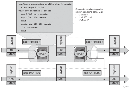
2.3.3. Connection Profile VLAN SAPs
The connection-profile-vlan SAPs (CP SAPs) allow the association of a range of customer VIDs to a given SAP. CP SAPs can be used to build Layer 2 Services that are fully compatible with MEF 10.3 Bundling Service Attributes and RFC 7432 EVPN VLAN Bundle Service interfaces.
The config>connection-profile-vlan>vlan-range command defines the range of customer VIDs to be matched when the connection-profile-vlan is associated with a dot1q or QinQ SAP. The following CLI output example shows the use of connection-profile-vlan in dot1q and QinQ SAPs:
As far as VLAN manipulation is concerned, the CP SAP behavior is equivalent to the default SAP’s (when the ingress VID falls into the range configured in the CP), where the range of VIDs included is not service-delimiting and therefore, the VIDs are not pushed/popped. The main differences between the CP SAPs and the default SAPs are:
- Resources — A default SAP consumes one SAP instance, whereas a CP SAP consumes a number of SAP instances equal to the number of VLANs in the range. The amount of SAP instances consumed in the system can be checked by executing the following commands:*A:Dut# tools dump resource-usage system===============================================================================Resource Usage Information for System===============================================================================Total Allocated Free-------------------------------------------------------------------------------<snip>SAP Entries | 262143 8 262135===============================================================================*A:Dut# tools dump resource-usage card 1 fp 1===============================================================================Resource Usage Information for Card Slot #1 FP #1===============================================================================Total Allocated Free-------------------------------------------------------------------------------<snip>SAP Instances | 63999 254 63745<snip>===============================================================================Refer to the 7450 ESS, 7750 SR, 7950 XRS, and VSR Basic System Configuration Guide for a complete description of the tools dump resource-usage command.
- Unlike the default SAP, a CP SAP cannot co-exist with a vlan SAP that is in the same range. For example: 1/1/1:* and 1/1/1:100 can co-exist; in contrast, 2/1/1:cp-1 (cp-1 = vlan 1 to 200) and 2/1/1:100 cannot co-exist.
Figure 10 shows customer VID processing by SAPs with service-delimiting VIDs, and by CP SAPs. SAP 1/1/1:cp-1 does not strip off or push VID 10, whereas SAP 1/1/1:100 and SAP 1/1/1:200 do strip off and push the corresponding VID.
Figure 10: VLAN Tag Handling
A connection-profile-vlan allows the configuration of VLAN ranges with the following characteristics.
- A vlan-range can be defined as a single VID (for example, vlan-range 101), or two VIDs delimiting the beginning and the end of the range (for example, vlan-range 105 to 107).
- Discontinuous ranges are allowed.
- Overlapping ranges are not allowed within the same connection-profile-vlan. VLAN range overlapping can exist across different connection-profiles as long as they are not applied to the same port (in the case of dot1q ports), or the same port and service-delimiting tag (in the case of qinq ports). For example:
- 1/1/1:x.cp-1 and 1/1/1:y.cp-2 can coexist on the same port, where cp-1 includes vids [10-20] and cp-2 includes vids [15-25]
- If x=y, then the overlapping is not possible in the above case.
- A connection-profile-vlan must have at least one range (with a single or multiple VIDs) before it can be associated with a SAP.
- A connection-profile-vlan cannot contain an explicitly defined SAP within any of the ranges when the explicit SAP is configured on the same port.
- The configured VLAN ranges cannot contain VIDs 0 or 4095.
- The connection-profile-vlan SAPs are supported in Layer 2 services only. No IES or VPRN services can contain CP SAPs.
- CP SAPs are supported on access or hybrid ports but are not on network interfaces.
- CP SAPs are supported in (non-PBB) Epipe and VPLS services.
- CP SAPs support SAP based QoS policies. VID type MAC criteria can be used on CP SAPs to apply specific QoS on a given VLAN within the connection-profile-vlan.
- The legacy OAM commands (mac-ping, mac-trace, mac-purge, and mac-populate) do not work with CP SAPs.
2.3.3.1. Using connection-profile-vlan in Dot1q Ports
Table 5 describes the SAP lookup matching order that is applied when connection-profile-vlan is used in dot1q ports.
Table 5: SAP Lookup Matching Order for Dot1q Ports
Incoming Frame qtag VID value | SAP lookup precedence order (:0 and :* are mutually-exclusive on the same port) | |||
:X | :CP | :0 | :* | |
x (belongs to the CP range) | 1st | 1st | 2nd | |
0 | 1st | 1st | ||
<untagged> | 1st | 1st | ||
2.3.3.2. Using connection-profile-vlan in QinQ Ports
Table 6 describes the SAP lookup matching order that is applied when connection-profile-vlan is used in QinQ ports.
Table 6: SAP Lookup Matching Order for QinQ Ports
Incoming Frame | System/port settings = new-qinq-untagged-sap | |||||||
qtag1.qtag2 | SAP lookup precedence order (assumption: X and Y are defined in CP ranges) | |||||||
:X.Y | :X.0 | :X.CP | :CP.* | :X.* | :0.* | :*.null | :*.* | |
x.y | 1st | 1st | 2nd | 2nd | 3rd | |||
x.0 | 1st | 2nd | 2nd | 3rd | ||||
0.y | 1st | 2nd | ||||||
0.0 | 1st | 2nd | ||||||
x | 1st | 2nd | 2nd | 3rd | 4th | |||
0 | 1st | 2nd | 3rd | |||||
<untagged> | 1st | 2nd | 3rd | |||||
Consider the following when using connection-profile-vlan (CP) in qinq ports:
- A CP can be defined for inner or outer tags but not both at the same time; for example, :X.CP and :CP.* are possible, but not ':CP.CP'.
- It is important to note that :CP:Y is not allowed; for example, if a CP is defined at the outer VID, the inner VID can only be a '*' or a '0'.
- :0.CP SAPs are not allowed; if the outer VID is 0, the inner VID cannot be a connection-profile-vlan value.
- A CP cannot contain a VID that is associated to an explicitly defined inner or outer tag in a specific port. For example, assuming that X and Y are tags defined in 'CP', a given port can be defined with ":X.CP" or ":Y.CP" but not with ":X.CP" or ":Y.CP".
- The following combinations are allowed:
- :CP.0 - matches frames with outer tags contained in CP and inner tags 0 or null
- :CP.* - matches frames with outer tags contained in CP and any inner tags
- In the case where a VLAN tag combination matches different SAPs, the highest priority SAP will be picked, irrespective of its oper-status, as long as the SAP is still created. Therefore, if the SAP is down, the frames will not go to a different SAP. For example, suppose that ingress frames with VIDs 10.25 are classified as part of sap 10.cp-1. Only when sap 10.cp-1 is removed from the configuration will the frames with VIDs 10.25 go to sap cp-1.*.
2.3.4. Service Distribution Points
A Service Distribution Point (SDP) acts as a logical way to direct traffic from one router to another through a uni-directional (one-way) service tunnel. The SDP terminates at the far-end device which directs packets to the correct service egress SAPs on that device. A distributed service consists of a configuration with at least one SAP on a local node, one SAP on a remote node, and an SDP binding the service to the service tunnel.
An SDP has the following characteristics:
- An SDP is locally unique to a participating routers. The same SDP ID can appear on other Nokia routers.
- An SDP uses the system IP address to identify the far-end edge router.
- An SDP is not specific to any one service or any type of service. Once an SDP is created, services are bound to the SDP. An SDP can also have more than one service type associated with it.
- All services mapped to an SDP use the same transport encapsulation type defined for the SDP (either GRE, MPLS, or L2tPv3).
- An SDP is a management entity. Even though the SDP configuration and the services carried within are independent, they are related objects. Operations on the SDP affect all the services associated with the SDP. For example, the operational and administrative state of an SDP controls the state of services bound to the SDP.
An SDP from the local device to a far-end router requires a return path SDP from the far-end router back to the local router. Each device must have an SDP defined for every remote router to which it wants to provide service. SDPs must be created first, before a distributed service can be configured.
2.3.4.1. SDP Binding
To configure a distributed service from ALA-A to ALA-B, the SDP ID (1) (shown in Figure 11) must be specified in the service creation process in order to “bind” the service to the tunnel (the SDP). Otherwise, service traffic is not directed to a far-end point and the far-end device(s) cannot participate in the service (there is no service). To configure a distributed service from ALA-B to ALA-A, the SDP ID (5) must be specified.
Figure 11: GRE Service Distribution Point (SDP) Pointing From ALA-A to ALA-B
2.3.4.2. Spoke and Mesh SDPs
When an SDP is bound to a service, it is bound as either a spoke SDP or a mesh SDP. The type of SDP indicates how flooded traffic is transmitted.
A spoke SDP is treated like the equivalent of a traditional bridge “port” where flooded traffic received on the spoke SDP is replicated on all other “ports” (other spoke and mesh SDPs or SAPs) and not transmitted on the port it was received.
All mesh SDPs bound to a service are logically treated like a single bridge “port” for flooded traffic where flooded traffic received on any mesh SDP on the service is replicated to other “ports” (spoke SDPs and SAPs) and not transmitted on any mesh SDPs.
2.3.4.3. SDP Using BGP Route Tunnel
SDP is enhanced to use BGP route tunnel to extend inter-AS support for routes and services. An SDP can be configured based on service transport method (for example, GRE or MPLS tunnel). MPLS SDP support is enhanced to allow a BGP route tunnel to reach the far-end PE.
A single method of tunneling is allowed per SDP (for example, LDP, RSVP-TE LSP or BGP route tunnel).
For the inter-AS far-end PE, next-hop for BGP route tunnel must be one of the local ASBR. The LSP type selected to reach the local ASBR (BGP labeled route next-hop) must be configured under the BGP global context. LDP must be supported to provide transport LSP to reach the BGP route tunnel next-hop.
Only BGP route labels can be used to transition from ASBR to the next-hop ASBR. The global BGP route tunnel transport configuration option must be entered to select an LSP to reach the PE node from ASBR node. On the last BGP segment, both BGP and LDP and LDP routes may be available to reach the far-end PE from the ASBR node. LDP LSP must be preferred due to higher protocol priority. This leads to just one label besides other labels in stack to identify VC or VPN at far-end PE nodes.
2.3.4.4. SDP Keepalives
SDP keepalives actively monitor the SDP operational state using periodic Nokia SDP ping echo request and echo reply messages. Nokia SDP ping is a part of Nokia’s suite of service diagnostics built on an Nokia service-level OA&M protocol. When SDP ping is used in the SDP keepalive application, the SDP echo request and echo reply messages are a mechanism for exchanging far-end SDP status.
Configuring SDP keepalives on a given SDP is optional. SDP keepalives for a particular SDP have the following configurable parameters:
- Admin up/admin down state
- Hello time
- Message length
- Max drop count
- Hold down time
SDP keepalive echo request messages are only sent when the SDP is completely configured and administratively up and SDP keepalives is administratively up. If the SDP is administratively down, keepalives for the SDP are disabled.
SDP keepalive echo request messages are sent out periodically based on the configured Hello Time. An optional message length for the echo request can be configured. If max drop count echo request messages do not receive an echo reply, the SDP will immediately be brought operationally down.
If a keepalive response is received that indicates an error condition, the SDP will immediately be brought operationally down.
Once a response is received that indicates the error has cleared and the hold down time interval has expired, the SDP will be eligible to be put into the operationally up state. If no other condition prevents the operational change, the SDP will enter the operational state.
2.3.4.5. SDP Administrative Groups
This feature introduces the support of SDP administrative groups, referred to as SDP admin groups. SDP admin groups provide a way for services using a pseudowire template to automatically include or exclude specific provisioned SDPs. SDPs sharing a specific characteristic or attribute can be made members of the same admin group.
The user first creates the admin groups that are to be used by SDPs on this node:
config>service>sdp-group>group-name group-name value group-value create
A maximum of 32 admin groups can be created. The no option is only allowed if the group-name is not referenced in a PW template or SDP.
The group value ranges from zero (0) to 31. It is uniquely associated with the group name at creation time. If the user attempts to configure another group name for a group value that is already assigned to an existing group name, the SDP admin group creation is failed. The same happens if the user attempts to configure an SDP admin group with a new name but associates it to a group value already assigned to an existing group name.
Next, the user configures the SDP membership in admin groups:
config>service>sdp>sdp-group group-name
The user can enter a maximum of one (1) admin group name at once. The user can execute the command multiple times to add membership to more than one admin group. The admin group name must have been configured or the command is failed. Admin groups are supported on an SDP of type GRE and of type MPLS (BGP/RSVP/LDP). They are also supported on an SDP with the mixed-lsp-mode option enabled.
The user then selects which admin groups to include or exclude in a given pseudowire template:
config>service>pw-template>sdp-include group-name
config>service>pw-template>sdp-exclude group-name
The admin group name must have been configured or the command is failed. The user can execute the command multiple times to include or exclude more than one admin group. The sdp-include and sdp-exclude commands can only be used with the use-provisioned-sdp or prefer-provisioned-sdp options. If the same group name is included and excluded within the same PW template, only the exclude option will be enforced.
Any changes made to the admin group sdp-include and sdp-exclude constraints will only be reflected in existing spoke SDPs after the following command has been executed:
tools>perform>service>eval-pw-template>allow-service-impact
When the service is bound to the PW template, the SDP selection rules will enforce the admin group constraints specified in the sdp-include and sdp-exclude commands.
config>service>vpls>bgp>pw-template-binding policy-id
config>service>epipe>spoke-sdp-fec>pw-template-bind policy-id
| Note: The group value is used to uniquely identify an SDP admin group throughout the network in NSP NFM-P. The node will send both the group name and value to NSP NFM-P (or other SNMP device) at the creation of the SDP admin group. In all other operations in the node, such as adding an SDP to an admin group or including or excluding an SDP admin group in a service context, only the group name is sent to NSP NFM-P or the SNMP device. |
SDP admin groups can be enabled on all router services that make use of the pseudowire template (BGP-AD VPLS service, BGP-VPLS service, BGP-VPWS and FEC129 VLL service). In the latter case, SR OS provides support at the T-PE nodes only.
2.3.4.6. SDP Selection Rules
In the current SDP selection process, all provisioned SDPs with the correct far-end IP address, the correct tunnel-far-end IP address, and the correct service label signaling are considered. The SDP with the lowest admin metric is selected. If more than one SDP with the same lowest metric are found, then the SDP with the highest sdp-id is selected. The type of SDP, GRE or MPLS (BGP/RSVP/LDP) is not a criterion in this selection.
The selection rule with SDP admin groups is modified such that the following admin-group constraints are applied up front to prune SDPs that do not comply:
- If one or more sdp-include statement is part of the PW template, then an SDP that is a member of one or more of the included groups will be considered. With the sdp-include statement, there is no preference for an SDP that belongs to all included groups versus one that belongs to one or fewer of the included groups. All SDPs satisfying the admin-group constraint will be considered and the selection above based on the lowest metric and highest sdp-id is applied.
- If one or more sdp-exclude statement is part of the PW template, then an SDP that is a member of any of the excluded groups will not be considered.
2.3.4.7. Class-Based Forwarding
2.3.4.7.1. Application of Class-Based Forwarding over RSVP LSPs
Class-based forwarding over RSVP LSPs allows a service packet to be forwarded over a specific RSVP LSP, part of an SDP, based on its ingress determined forwarding class. The LSP selected depends on the operational status and load-balancing algorithms used for ECMP and LAG spraying.
Figure 12: Class-Based Forwarding over SDP LSPs
Figure 12 illustrates the use of class-based forwarding to direct packets of a service to specific RSVP or static LSPs that are part of the same SDP based on the packets' forwarding class. The forwarding class of the packet is the one assigned to the packet as a result of applying the ingress QoS policy to the service SAP. The VLL service packets are all classified into the ef forwarding class and those that are destined to PE2 are forwarded over LSP1. Multicast and broadcast are classified into the be class and are forwarded over LSP2.
This feature allows service providers to dedicate specific LSPs with a determined level of traffic engineering and protection to select service packets. For example, packets of a VoIP service are assigned the ef class to expedite their forwarding but are also sent over carefully traffic-engineered and FRR-protected LSP paths across the service provider network.
2.3.4.7.2. Operation of Class-Based Forwarding over RSVP LSPs
The Nokia router’s class-based forwarding feature applies to a set of LSPs that are part of the same SDP. Each LSP must be configured as part of an SDP specifying the forwarding classes it will support. A forwarding class can only be assigned to one LSP in a given SDP, meaning that only one LSP within an SDP will support a given class of service. However, multiple classes of services can be assigned to an LSP. Both RSVP and static LSPs are allowed. All subclasses will be assigned to the same LSP as the parent forwarding class.
When a service packet is received at an ingress SAP, it is classified into one of the eight forwarding classes. If the packet will leave the SR on an SDP that is configured for class-based forwarding, the outgoing LSP will be selected based on the packet's forwarding class. Each SDP has a default LSP. The default LSP is used to forward a received packet that was classified at the ingress SAP into a forwarding class for which the SDP does not have an explicitly-configured LSP association. It is also used to forward a received packet if the LSP supporting its forwarding class is down.
| Note: The SDP goes down if the default LSP is down. |
Class-based forwarding can be applied to all services supported by the Nokia routers. For VPLS services, explicit FC-to-LSP mappings are used for known unicast packets. Multicast and broadcast packets use the default LSP. There is a per-SDP user configuration that optionally overrides this behavior to specify an LSP to be used for multicast/broadcast packets.
VLL service packets are forwarded based on their forwarding class only if shared queuing is enabled on the ingress SAP. Shared queuing must be enabled on the VLL ingress SAP if class-forwarding is enabled on the SDP the service is bound to. Otherwise, the VLL packets will be forwarded to the LSP which is the result of hashing the VLL service ID. Since there are eight entries in the ECMP table for an SDP, one LSP ID for each forwarding class, the resulting load balancing of VLL service ID is weighted by the number of times an LSP appears on that table. For instance, if there are eight LSPs, the result of the hashing will be similar to when class based forwarding is disabled on the SDP. If there are fewer LSPs, then the LSPs which were mapped to more than one forwarding class, including the default LSP, will have proportionally more VLL services forwarding to them.
Only user packets are forwarded based on their forwarding class. OAM packets are forwarded in the same way as an SDP with class-based forwarding disabled. In other words, LSP ping and LSP trace messages are queued in the queue corresponding to the forwarding class specified by the user and are forwarded over the LSP being tested. Service and SDP OAM packets, such as service ping, VCCV ping, and SDP ping are queued in the queue corresponding to the forwarding class specified by the user and forwarded over the first available LSP.
Class-based forwarding is not supported for protocol packets tunneled through an SDP. All packets are forwarded over the default LSP.
Class-based forwarding is not supported on a spoke SDP used for termination on an IES or VPRN service. All packets are forwarded over the default LSP.
2.3.4.8. Source IPv4 Address Configuration in GRE SDP and GRE Tunnel
2.3.4.8.1. Introduction and Feature Configuration
When the GRE tunnel is used as part of a provisioned SDP, the following command is relaxed to allow the user to configure a source address for an GRE SDP:
configure>service>sdp>local-end ip-address
The default value of the local-end parameter is the primary IPv4 address of the system interface. To change the local-end address, the SDP must be shut down.
The primary IPv4 address of any local network IP interface, loopback or otherwise, may be used as the source address. The address does not need to match the primary address of an interface which has the MPLS-over-GRE termination subnet configured, unless a GRE SDP or tunnel from the far-end router terminates on this address.
The address of the following interfaces are not supported:
- unnumbered network IP interface
- IES interface
- VPRN interface
- CSC VPRN interface
The following rules apply to the local-end command:
- A maximum of 15 distinct address values can be configured for all GRE SDPs under the configure>service>sdp>local-end context, and all L2oGRE SDPs under the config>service>system>gre-eth-bridged>tunnel-termination context.The same source address cannot be used in both contexts since an address configured for a L2oGRE SDP matches an internally created interface which is not available to other applications.
- The local-end address of a GRE SDP, when different from system, need not match the primary address of an interface which has the MPLS-over-GRE termination subnet configured, unless a GRE SDP or tunnel from the far-end router terminates on this address.
The user must ensure that the local-end address is reachable from the far-end router that terminates the GRE SDP. To help ensure reachability, the interface for this address may be added to IGP or BGP, or a static route may be configured on the far-end router.
The following services can be bound to a GRE SDP when the local-end address is modified:
- VPRN or IES with a spoke-sdp interface(configure>service>vprn>interface>spoke-sdp)
- VPLS with provisioned spoke-sdp
- BGP-AD VPLS and use-provisioned-sdp or prefer-provisioned-sdp option enabled
- BGP-VPLS and use-provisioned-sdp or prefer-provisioned-sdp or prefer-provisioned option enabled
- Epipe with provisioned spoke-sdp
- Epipe with BGP-VPWS and use-provisioned-sdp or prefer-provisioned-sdp or prefer-provisioned option enabled
For services that support auto-binding to a GRE tunnel, a new CLI command is introduced to configure a single alternate source address per system:
configure>service>system>vpn-gre-source-ip ip-address
The default value is the primary IPv4 address of the system interface.
A change to the value of the vpn-gre-source-ip parameter can be performed without shutting down the service. Once the new value is configured, the system address will not be used in services that bind to the GRE tunnel.
The primary IPv4 address of any local network IP interface, loopback or otherwise, may be used.
The address of the following interfaces are not supported:
- unnumbered network IP interface
- IES interface
- VPRN interface
- CSC VPRN interface
The following rules apply to the vpn-gre-source-ip parameter value:
- This single source address counts towards the maximum of 15 distinct address values per system that are used by all GRE SDPs under the configure>service>sdp>local-end context and all L2oGRE SDPs under the config>service>system>gre-eth-bridged>tunnel-termination context.
- The same source address can be used in both vpn-gre-source-ip and configure>service>sdp>local-end contexts.
- The same source address cannot be used in both vpn-gre-source-ip and config>service>system>gre-eth-bridged>tunnel-termination contexts because an address configured for a L2oGRE SDP matches an internally created interface that is not available to other applications.
- The vpn-gre-source-ip address, when different from system, need not match the primary address of an interface which has the MPLS-over-GRE termination subnet configured, unless a GRE SDP or tunnel from the far-end router terminates on this address.
The following contexts can use a GRE tunnel when the source IP address is modified:
- VPRN service with a SDP (config>service>vprn>spoke-sdp)
- VPRN auto-bind-tunnel
The source address cannot be configured for the following services with auto-created GRE-SDP:
- BGP-AD VPLS
- BGP-VPLS
- VGP-VPWS
An alternative solution to bind any one of these services to its own specific GRE SDP with its own source IP address, is to tag a pre-provisioned GRE SDP with a SDP admin-group (sdp-group command) and include the admin-group with the PW template binding of this service (config>service>pw-template policy-id [use-provisioned-sdp]> sdp-include group-name). The command prefer-provisioned-sdp can also be used.
2.3.4.8.2. Feature Operation with T-LDP and BGP Service Label Signaling
The origination function continues to operate as in previous releases. The only change is the ability to insert the user configured address in the source address field of the GRE/IPv4 header as explained in Introduction and Feature Configuration.
| Note: The service manager does not explicitly request from the LDP module that an SDP auto-generated T-LDP session for the MPLS-over-GRE SDP uses the source address configured with the local-end CLI command. LDP ensures that either a user-configured T-LDP session, or a peer template based auto-created T-LDP session, exists and is connected to the far-end address of the SDP. LDP will use one of these sessions, or will auto-create one using the default local transport address of system. |
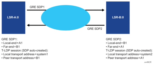
Consequently, if the source transport address used by the T-LDP control plane session does not match the destination transport address set by the remote PE in the targeted LDP Hello messages, the T-LDP session does not come up.
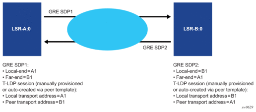
For example, the setup in Figure 13 will result in both GRE SDP1 and SDP2 to remain down because the targeted Hello adjacency and LDP session will not come up between the two LDP LSRs.
Figure 13: Mismatched T-LDP Control Plane Parameters
The user must match the local transport address of the T-LDP session to the local-end address of the GRE SDP in both the local and remote PE routers. This can be achieved by manually configuring a T-LDP session to the peer, or by auto-creating a T-LDP session with the targeted peer template feature, and setting the local-lsr-id command to the address configured in the local-end command of the GRE SDP. In addition, the far-end address must be in a GRE termination subnet at the remote PE and be the primary address of an interface in order for T-LDP to use it as its local LSR ID at the remote PE. Figure 14 shows an example of a correct configuration.
Figure 14: Proper Setting of T-LDP Control Plane Parameters
The source address used by the GRE tunnel in the data plane can be different than the local transport address used by T-LDP in the control plane and the GRE SDPs will still come up. For example, the setup in Figure 15 uses at each end the system address for the T-LDP session but uses a loopback interface address as the source address of the GRE SDP.
Figure 15: Source Address Mismatch between Control and Data Planes

| Note: The LDP uses a priority mechanism to select which parameters to use to instantiate a T-LDP session to the same far-end transport address. A manually provisioned T-LDP session overrides one that is signaled using the targeted peer template which overrides one that is auto-created by an SDP. This is done automatically by LDP by issuing, an ad-hoc update to the Hello message to the far-end with the new parameters. As long as the corresponding change is performed at the far-end router to match the local-end parameter change (for example, changing the local transport address requires a change of the far-end transport address in the remote LSR to the same value) the T-LDP session remains up while the Hello adjacency is being synchronized by both LSRs. |
The same recommendation applies when the SDP uses BGP for signaling the VC labels of the services. The user must configure the BGP session to the peer and set the local-address CLI command under the BGP group context or under the neighbor context to the address configured in the local-end command of the GRE SDP.
Replies to OAM messages such as an SDP keep-alive and sdp-ping are sent by the far-end PE using the MPLS-over-GRE encapsulation to the source address of the received OAM message. This means, the source transport address of the T-LDP control plane session or the BGP control plane session is used for the signaling of the VC-label in the local PE. Replies to OAM messages when the VC label is static are sent to the source address of the local PE. In all cases however, the system can properly extract them to the CPM as long as the subnet of that local interface is reachable.
2.3.5. SAP and MPLS Binding Loopback with MAC Swap
SAPs and MPLS SDP bindings within Ethernet services, Epipe and VPLS, may be placed into a loopback mode that allows all packets that arrive on the looped entity to be reflected back into the service. The function is specific to the entity on which the loopback is configured and is non-disruptive to other SAPs and SDP bindings on the same port or LAG.
Epipe and PBB Epipe service constructs support both ingress and egress loopbacks on Ethernet SAPs or MPLS SDP bindings.
VPLS and I-VPLS service constructs support both in ingress and egress loopback on Ethernet SAPs or MPLS SDP bindings.
Do not enable this functionality in the core PBB context because there is no ISID awareness. If this feature is enabled within the core PBB context all traffic that arrives on the B-SAP or B-MPLS binding will be looped back into the PBB context without regard for ISID or customer specific MAC headers.
An ingress loopback configured on the entity will have the following effects on forwarding for the entity:
- Traffic arriving on the entity will be looped back to the same entity, via the fabric.
- Traffic that is attempting to egress that entity from another SAP or SDP binding within the service will be blocked.
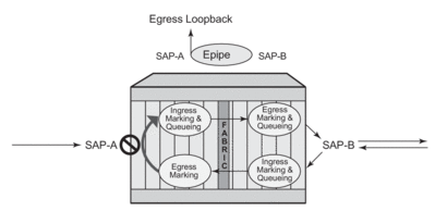
Essentially an ingress loopback function will isolate the SAP or MPLS SDP binding from the rest of the service. Figure 16 uses a simple Epipe service to illustrate the various touch points and processing that occurs on a packet that is processed by an ingress loopback as it moves through the network element.
Figure 16: Ingress Loopback
.gif)
An egress loopback configured on the entity will have the following effects on the forwarding for the entity.
- Traffic that arrives on any service SAP or SDP binding that is forwarded to an egress that is in loopback will be looped back into the service.
- Any traffic that is attempting to gain access to the service from that entity (ingress the network element from the entity) will be dropped.
In the case of the egress loopback, the SAP or MPLS SDP binding is not isolated from the rest of the service it remains part of the service and reflects traffic back into the service. Extreme care must be used when considering the application of an egress loopback in a VPLS or I-VPLS service. Since a VPLS service rely on MAC based forwarding any packet that arrives at an egress loopback will be reflected back into the service and use MAC based forwarding to apply the proper forwarding decision. If this is a live multipoint service with active endpoints this could have very negative effects on the service and the clients connected to this service. Even if the forwarding database is primed any broadcast, unknown or multicast that arrives in the service will arrive on the egress loopback and will be reflected back into the service causing at the very least duplication of all of this type of traffic.
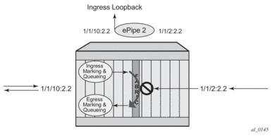
Figure 17 uses a simple Epipe service to illustrate the various touch points and processing that occurs on a packet that is processed by an egress loopback as it moves through the network element. Egress processing will not perform queuing functions on the egress it will only perform the functions of the forwarding plane like remarking.
Figure 17: Egress Loopback
The operational state of the SAP or MPLS SDP binding will not change as a result of the loopback function. This means a SAP or MPLS SDP binding that is operationally up will not change state strictly because of the loopback be started or stopped. Of course control protocols that are attempting to gain access via the entity that is not allowing packets to enter the service will eventually time out.
Care must be taken when considering the use of control protocols in a service with enabled loopbacks. The operator must be very aware of the impact that interrupting control protocols can have on the state of the SAP. When SAPs are dynamically created using a protocol or a protocol is required to maintain the operational state of the SAP, interruption of this control protocol will cause the SAP to fail. Other SAPs linking their state to a failed SAP will react to that failure as well. This loopback function is per Ethernet SAP or MPLS SDP binding. This means that all traffic that is extracted and sent to the CPM prior to the loopback process will all be looped back to in the direction it was received, or in the case of VPLS, back into the service. All service based control protocols that are included with this service should be removed to ensure the loopback process is handling the packets and not some other function on the node that can extract the control protocol but never respond because the service is block. However, there may be instances where an operator would want to continue to run control protocols for the service during a loopback. For example, Down MEPs on an Ethernet SAP could continue to process ETH-CFM packets if the loopback is on the mate Ethernet SAP and was configured as an egress loopback.
By default no MAC swap functions are performed. Options are available to allow for various MAC swap functions. Table 7 lists the various options and functions based on the configured mac-swap and associated options.
Table 7: MAC-SWAP Configuration and Options
Configuration | Reflection with Inbound DA | ||||
Action | Options | Unicast (Learned) | Unicast (Unknown) | Broadcast | Multicast |
mac-swap | no options | Swap SA to DA Swap DA to SA | Swap SA to DA Swap DA to SA | Drop | Drop |
mac-swap | mac | Swap SA to DA Swap DA to SA | Swap SA to DA Swap DA to SA | Swap SA to DA Static MAC= SA | Swap SA to DA Static MAC= SA |
mac-swap | mac + all | Swap SA to DA Static MAC= SA | Swap SA to DA Static MAC= SA | Swap SA to DA Static MAC= SA | Swap SA to DA Static MAC= SA |
none | none | No swapping | No swapping | No swapping | No swapping |
Only the outer Layer 2 header can be manipulated.
In order for the loopback function to operate, the service must be operationally up, and the SAP, port, or LAG must be administratively up. In the case of a LAG, the LAG must have members port that are administratively up. If any of these conditions are not met, the loopback function will fail.
A SAP that is configured for egress loopback is not required to be operationally up, and the cabling does not need to be connected to the port. However, all necessary hardware must be installed in the network element for the ingress packets to be routed to the egress. Ghost ports do not support loopback operations.
An Epipe service will enter an operationally Down state when one of the SAPs is non-operational. The service state will remain or be returned to an operational state if the ignore-oper-down command is configured under the non-operational SAP. A VPLS service will remain operational as long as one SAP in the service is operational. However, if the SAP is a VPLS is configured over a LAG, the SAP is removed from the forwarding table if it has a non-operational state, and, consequently, packets will never reach the egress. The process-cpm-traffic-on-sap-down command can be configured under the VPLS SAP over a LAG to allow the LAG SAP to be reached even with a non-operational SAP.
If the service state is not operational or the egress SAP is not reachable via the forwarding plane, the traffic will never arrive on the SAP to be looped.
MPLS SDP bindings must be operationally up or the loopback function will fail.
In order to configure this functionality the operator is required to us use the tools hierarchy. In this specific case, the loopback tools supporting this functionality may be configured through CLI or through SNMP. However, these commands are never resident in the configuration. This means the loopback will survive high availability events that cause one CPM to change from standby to active, as well as ISSU function or IOM resets (hard or soft). However the function will not survive a complete node reboot.
In the case on SNMP, it is possible to configure a static mac address for the mac swap function without actually invoking the mac-swap. This is not possible through the CLI.
This function requires a minimum of IOM/IMM.
This feature is mutually exclusive with functions that use mirroring.
Figure 18 shows an example for placing sap 1/1/10:2.2 in service id 2 (an Epipe) in an active loopback mode with a mac-swap for all broadcast and multicast destined packets.
Figure 18: Active Loopback Mode
To stop the loopback, a simple stop command is required.
2.3.6. Promiscuous ETH-LBM Mode of Operation
ETH-CFM MEPs support the processing of ETH-CFM PDUs without interrupting the flow of service data. ETH-CFM processing identifies, processes, and responds to the appropriate ETH-CFM PDUs directed at the target MEP using domain-level logic comparison, equal to and lower. This behavior lends itself well to the testing of connectivity, performance monitoring, and path information. The pinpoint ETH-CFM processing logic also lends itself well to service activation testing streams encapsulated in ETH-LBM frames.
The lbm-svc-act-responder configuration option allocates additional resources to the associated MEP to process high-speed service activation streams encapsulated in ETH-LBM frames. When a MEP is created with this option, it streamlines the processing of the inbound ETH-LBM frame. This is accomplished by performing basic ETH-CFM header parsing, replacing the inbound ETH-LBM operational code (03) with the outbound ETH-LBR operational code (02), swapping source and destination MAC addresses, and reflecting any Data TLVs and other data contained in the PDU without validation. A MEP configured with the lbm-svc-act-responder configuration option will operate in promiscuous ETH-LBM mode.
Promiscuous ETH-LBM mode bypasses some checks and extended functions typically performed by a MEP. In this mode, the MEP will not validate the Layer 2 destination MAC address of the arriving ETH-LBM frame to ensure that it matches the MEP. ETH-LB system statistics and per-MEP statistics, as well as ETH-LB specific counters, will not be incremented. CFM debugging will not be available for these ETH-LB packets.
Only ETH-LBM PDUs at the same domain level as the MEP that is configured with the lbm-svc-act-responder function will access the additional resources required to accommodate high-speed service activation processing. Normal processing of ETH-CFM packets will occur for all other ETH-CFM PDUs that arrive on the MEP with the same domain level. The MEP will also process and terminate the lower levels as per normal processing. To ensure proper handling of the service activation stream encapsulated in the ETH-LBM PDU, the level of all ETH-LBM packets in the stream must equal that of the target MEP with the lbm-svc-act-responder command.
This mode of operation is supported for Up and Down MEPs in Epipe and VPLS services as well as for base router interfaces. This functionality requires a minimum of FP3 hardware.
2.4. Multi-Service Sites
A customer site can be designated a multi-service site where a single scheduler policy is applied to all SAPs associated with the site while retaining per-service and per-forwarding class shaping and policing. The SAPs associated with the multi-service site can be on a single port or on a single slot. The SAPs in a multi-service site cannot span slots.
Multi-service sites are anchor points to create an ingress and egress virtual scheduler hierarchy. When a site is created, it must be assigned to a chassis slot or port. When scheduler policies are defined for ingress and egress, the scheduler names contained in each policy are created according to the parameters defined in the policy. Multi-service customer sites exist for the sole purpose of creating a virtual scheduler hierarchy and making it available to queues on multiple Service Access Points (SAPs).
The scheduler policy association with the customer site normally prevents the scheduler policy from being deleted until after the scheduler policy is removed from the customer site.
When the multi-service customer site is created, an ingress and egress scheduler policy association does not exist. This does not prevent the site from being assigned to a chassis slot or prevent service SAP assignment. After the site has been created, the ingress and egress scheduler policy associations can be assigned or removed at any time.
Each customer site must have a unique name within the context of the customer. Modifications made to an existing site immediately affect all SAPs associated with the site. Changing a scheduler policy association can cause new schedulers to be created and existing policers and queues on the SAPs to no longer be orphaned. Existing schedulers on the site may cease to exist, causing queues relying on that scheduler to be orphaned.
2.5. G.8031 Protected Ethernet Tunnels
G.8031 Protected Ethernet Tunnels is supported only on the 7450 ESS and 7750 SR.
The Nokia implementation of Ethernet Tunnels offers ITU-T G.8031 specification compliance to achieve 50 ms resiliency for failures in a native Ethernet backbone for native Layer 2 networks.
Ethernet Automatic Protection Switching (APS) as defined in ITU-T recommends G.8031 provides a linear 1:1 or 1+1 protection switching mechanism for VLAN-based Ethernet networks. The OS implementation of G.8031 supports 1:1 linear protection through implementation of point-to-point Ethernet Tunnels providing a working and protecting Ethernet circuit, where the path providing the protection is always available through health-monitoring. The 1:1 model is common practice for packet based services since it makes best use of available bandwidth.
Within each path, Y.1731 Maintenance Entity Group (MEG) Endpoints (MEPs) are used to exchange APS-specific information (specifically to co-ordinate switchovers) as well as optionally fast Continuity Check Messages (CCM) providing an inherent fault detection mechanism as part of the protocol. Failure detection of a working path by one of the mechanisms triggers to move from working to protecting circuits. Upon failure, re-convergence times are a dependent on the failure detection mechanisms. In the case of Y.1731, the CCM transmit interval determines the response time. The OS supports message timers as low as 10 milliseconds so the restoration times are comparable to SONET/SDH. Alternatively, 802.3ah (Ethernet in the First Mile) or simple Loss of Signal can act as a trigger for a protection switch where appropriate.
Revertive or non-revertive behavior can be configured based on service provider environment. Revertive behavior is commonly deployed since it restores the traffic to a predictable state.
Ethernet APS can be configured on any port configured for access mode using dot1q or Q-in-Q encapsulation enabling support for Ethernet APS protected services on the service edge towards the customer site, or within the Ethernet backbone. ELINE, E-LAN, and E-Tree services can be afforded Ethernet APS protection and, although the Ethernet Tunnel providing the protection has a working/protecting path that is presented to the service as a single logical entity to the service layer. The intention of this is to cause minimum disruption to the service during Ethernet APS failure detection and recovery.
Figure 19: PBB G.8031 Protected Ethernet Tunnel Example
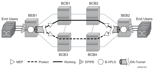
In the implementation, the Ethernet tunnel is a logical interface for a SAP defined Layer 2 service similar to a LAG. The implementation offers ITU G.8031 1:1 compliance as well as some added capabilities such as fate sharing and emulated LAG support.
- Synchronization between services such that both send and receive on the same Ethernet path in stable state.
- Revertive/non-revertive choices.
- Emulated-LAG co-existence.
It is important that the configuration for the various services does not change when a new Ethernet tunneling type is introduced on the backbone side. This is achieved by using a SAP to map the eth-tunnel object into service instance.
The member port and control tag defined under each eth-tunnel path are then used for encapsulating and forwarding the CCMs and the G.8031 PDUs used for protection function, the latter frames being sent only on the secondary path. The configuration of the active path is also used to instantiate the SAP object in the forwarding plane.
If a failure of a link or node affects the primary eth-tunnel path, the services will fail to receive the CC messages exchanged on that path or will receive a fault indication from the link layer OAM module.
For fault detection using CCMs, a number of 3.5 CC intervals plus a configurable hold-off timer must be missed for a fault to be declared on the associated path. The latter mechanism is required to accommodate the existence of additional 50 ms resiliency mechanism in the optical layer. After it received the fault indication, the protection module will declare the associated path down, then sends an indication to the remote protection module to switch the transmit direction to the backup path.
In order to address unidirectional failures, the RDI bit will be set in CC messages transmitted in the reverse direction upon detection of failure at the receiving service. The same applies for link layer OAM. Until the protection switch indication arrives from the remote node, the local node will continue to receive frames from both primary and backup paths to avoid the loss of in-flight packets.
In case of direct connectivity between the nodes, there is no need to use Ethernet CCM messaging for liveliness detection. Link level detection mechanisms like LoS (Loss of Signal) or IEEE 802.3ah link layer OAM can be used to detect link or nodal failure. This can be achieved by not provisioning a MEP on the primary path.
Using the Ethernet Tunnel as a building block for Ethernet APS protection it is possible to provide different protection schemes with different fate-dependency; or indeed to mix protected and non-protected services on the same physical port.
The simplest model is the fate-independent model where each Ethernet Tunnel supports its own protection using Y.1731 CCMs for example. In this case a single VLAN Tag may be used for control and data traffic. In cases where Ethernet Tunnels can be guaranteed to share a common physical path, it is possible to implement a fate-sharing model. This approach provides the advantage of reducing the amount of Ethernet OAM signaling because only one control tag determines the fate of many user tags.
Epipe using BGP-MH site support for Ethernet tunnels (see the 7450 ESS, 7750 SR, 7950 XRS, and VSR Layer 2 Services and EVPN Guide: VLL, VPLS, PBB, and EVPN for more information) offers an enhancement to Ethernet tunnels enabling an Ethernet edge device using G.8031 to support multi-chassis redundancy for Epipe services. The G.8031 device configuration is standard on the Ethernet edge device, but the active link is controlled by BGP-multihoming just as with VPLS services. This Epipe feature offers a standards-based alternative for multihomed access.
Figure 20: PBB Fate-Independent Ethernet Tunnels
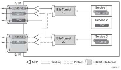
Figure 21: PBB Fate Sharing Ethernet Tunnels
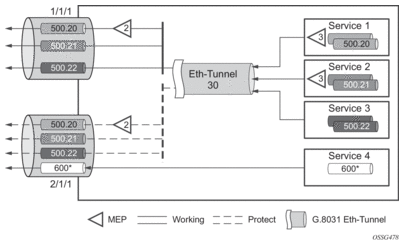
One of the advantages of access redundancy using Ethernet APS is that because it operates at the VLAN level protection mechanisms can be varied between services supported on the physical port. For example, it is possible to provide a protected service for “Premium” customers and also provide non-protected services for “Standard” users on the same physical port.
2.5.1. OAM Considerations
Ethernet CFM can be enabled on each individual path under an Ethernet tunnel. Only down MEPs can be configured on each of them and CCM sessions can be enabled to monitor the liveliness of the path using interval as low as 10 msec. Different CCM intervals can be supported on the primary and secondary paths in an Ethernet tunnel.
MEPs can still be configured under the services independent of the Ethernet Tunnels.
The following rules control the interaction between the MEP defined under the eth-tunnel path and the MEP defined in the service:
- The down MEPs configured on the eth-tunnel paths must be lower level than any down.
- MEPs configured on the associated SAP. The same applies for Virtual MEPs associated with services such as BVPLS. Checks are provided to prevent the user from configuring anything that violates the above rule. An error message is generated to indicate the mismatch.
- Other service MEPs (up direction, down higher levels) are allowed with no restriction.
- Any down MEP on the associated SAP will transmit only over the active path entity.
2.5.2. QoS Considerations
When Ethernet tunnel is configured on two member ports located on different IOMs, the SAP queues and virtual schedulers will be created with the actual parameters on each IOM.
The protection mode '8031-1to1' (default) activates only the primary path at any point in time, guaranteeing the use of the desired QoS resources.
Ethernet tunnel CC messages transmitted over the SAP queues using the default egress QoS policy will use NC (network class) as a forwarding class. If user traffic is assigned to the NC forwarding class, it will compete for the same bandwidth resources with the Ethernet CCMs. As CCM loss could lead to unnecessary bouncing of the Ethernet tunnel, congestion of the queues associated with the NC traffic should be avoided. The operator must configure different QoS Policies to avoid congestion for the CCM forwarding class by controlling the amount of traffic assigned into the corresponding queue.
2.5.3. Mirroring and Lawful Intercept Considerations
Mirroring and Lawful Intercept (LI) cannot use the eth-tunnel as a source. Also, a SAP configured on an eth-tunnel cannot be used as mirror destination. The CLI blocks the above options. The SAP configured on the eth-tunnel, a filter associated with it and the member ports in the eth-tunnel> path context can be used as mirror and LI source.
2.5.4. Support Service and Solution Combinations
The Ethernet tunnels are supported Layer 2 service VLL, VPLS and B-VPLS instances. The following considerations apply:
- Only ports in access or hybrid mode can be configured as eth-tunnel path members. The member ports can be located on the same or different IOMs or MDAs.
- Dot1q and QinQ ports are supported as eth-tunnel path members.
- The same port cannot be used as member in both a LAG and an Ethernet Tunnel but LAG emulation is supported.
- A mix of regular and multiple eth-tunnel SAPs and pseudowires can be configured in the same services.
- Split horizon groups in VPLS and BVPLS are supported on eth-tunnel SAPs. The use of split horizon groups allows the emulation of a VPLS model over the native Ethernet core, eliminating the need for P-MSTP.
- LAG Emulation offers another method offering MSTP or P-MSTP over Ethernet Tunnels.
- MC-LAG access multi-homing into services is supported in combination with Ethernet tunnels.
2.5.5. LAG Emulation using Ethernet Tunnels
Ethernet Tunnels can provide G.8031 Ethernet APS protection as described in G.8031 Protected Ethernet Tunnels, or they can operate in a load-sharing manner providing an emulated LAG function. Moreover, as multiple Ethernet Tunnels can be provisioned on the same physical link(s), it is possible that two physical links could support one or more Ethernet Tunnels supporting APS protection for protected services whilst concurrently supporting one or more Ethernet Tunnels in load-sharing mode for non-protected services.
When Ethernet Tunnels have the protection type set to load-sharing, the precedence is configured to secondary, making the tunnels equal in order to implement load-sharing capability. A path threshold parameter allows the load-sharing group to be declared down if the number of paths drops equal to or lower than the threshold value. The ‘lag-emulation’ context provides access to conventional LAG parameters such as the adapt-qos mode (link, port-fair or distributed bandwidth distribution) and per-fp-ing-queuing to ensure that only one ingress queue is instantiated for every physical link supported on the same FP complex.
A typical use case for LAG emulation is to allow unprotected Ethernet services to capitalize on the LAG capability. RSTP and MSTP can also be used to network VPLS or B-VPLS over the Ethernet tunnels. LAG Emulation is also recommended when you use BGP-MH site support for Ethernet tunnels.
2.6. G.8032 Ethernet Ring Protection Switching
Ethernet ring protection switching offers ITU-T G.8032 specification compliance to achieve resiliency for Ethernet Layer 2 networks. Similar to G.8031 linear protection (also called Automatic Protection Switching (APS)), G.8032 (Ethernet-ring) is built on Ethernet OAM and often referred to as Ring Automatic Protection Switching (R-APS).
Ethernet-rings are supported on VPLS SAPs (VPLS, I-VPLS, B-VPLS). VPLS services supporting Rings SAPs can connect to other rings and Ethernet service using VPLS and R-VPLS SAPs. Ethernet-rings enables rings for core network or access network resiliency. A single point of interconnection to other services is supported. The Ethernet-ring service is a VLAN service providing protection for ring topologies and the ability to interact with other protection mechanisms for overall service protection. This ensures failures detected by Ethernet-ring only result in R-APS switchover when the lower layer cannot recover and that higher layers are isolated from the failure.
Rings are preferred in data networks where the native connectivity is laid out in a ring or there is a requirement for simple resilient LAN services. Due to the symmetry and the simple topology, rings are viewed a good solution for access and core networks where resilient LANs are required. The SR OS implementation can be used for interconnecting access rings and to provide traffic engineered backbone rings.
Ethernet-rings use one VID per control per ring instance and use one (typically) or multiple VIDs for data instances per control instance. A dedicated control VLAN (ERP VLAN) is used to run the protocol on the control VID. G.8032 controls the active state for the data VLANs (ring data instances) associated with a control instance. Multiple control instances allow logically separate rings on the same topology.
The SR OS implementation supports DOT1q, QinQ and PBB encapsulation for data ring instances. The control channel supports dot1q and QinQ encapsulation. The control channel can support DOT1Q while the data channels use queuing if the global config>system>ethernet>new-qinq-untagged-sap command is enabled.
2.6.1. Overview of G.8032 Operation
R-APS messages that carry the G.8032 protocol are sent on dedicated protocol VLAN called the Ethernet Ring Protection (ERP) instance. In a revertive case, G.8032 Protocol ensures that one Ring Protection Link (RPL) owner blocks the RPL link. R-APS messages are periodically sent around the ring to inform other nodes in the Ring about the blocked port in the RPL owner node. In non-revertive mode any link may be the RPL. Y.1731 Ethernet OAM CC is the basis of the RAPs messages. Y.1731 CC messages are typically used by nodes in the ring to monitor the health of each link in the ring in both directions. However CC messages are not mandatory. Other link layer mechanisms could be considered – for example LOS (Loss of Signal) when the nodes are directly connected.
Initially each Ring Node blocks one of its links and notifies other nodes in the ring about the blocked link. Once a ring node in the ring learns that another link is blocked, the node unblocks its blocked link possibly causing FDB flush in all links of the ring for the affected service VLANs, controlled by the ring control instance. This procedure results in unblocking all links but the one link and the ring normal (or idle) state is reached. In revertive mode the RPL link will be the link that is blocked when all links are operable after the revert time. In non-revertive mode the RPL link is no different than other ring links. Revertive mode offers predictability particularly when there are multiple ring instances and the operator can control which links are block on the different instances. Each time there is a topology change that affects reachability, the nodes may flush the FDB and MAC learning takes place for the affected service VLANs, allowing forwarding of packets to continue. Figure 22 depicts this operational state:
Figure 22: 0-1 G.8032 Ring in the Initial State
When a ring failure occurs, a node or nodes detecting the failure (enabled by Y.1731 OAM CC monitoring) send R-APS message in both directions. This allows the nodes at both ends of the failed link to block forwarding to the failed link preventing it from becoming active. In revertive mode, the RPL Owner then unblocks the previously blocked RPL and triggers FDB flush for all nodes for the affected service instances. The ring is now in protecting state and full ring connectivity is restored. MAC learning takes place to allow Layer 2 packet forwarding on a ring. Figure 23 depicts the failed link scenario.
Figure 23: 0-1 G.8032 Ring in the Protecting State
Once the failed link recovers, the nodes that blocked the link again send the R-APS messages indicating no failure this time. This in turn triggers RPL owner to block the RPL link and indicate the blocked RPL link the ring in R-APS message, which when received by the nodes at the recovered link cause them to unblock that link and restore connectivity (again all nodes in the ring perform FDB flush and MAC learning takes place). The ring is back in the normal (or idle) state.
Within each path, Y.1731 Maintenance Entity Group (MEG) Endpoints (MEPs) are used to exchange R-APS specific information (specifically to co-ordinate switchovers) as well as optionally fast Continuity Check Messages (CCM) providing an inherent fault detection mechanism as part of the protocol. Failure detection of a ring path by one of the mechanisms triggers to activate the protection links. Upon failure, re-convergence times are a dependent on the failure detection mechanisms. In the case of Y.1731, the CCM transmit interval determines the response time. The router supports message timers as low as 10 milliseconds (also 100 ms) so the restoration times are comparable to SONET/SDH. Alternatively, 802.3ah (Ethernet in the First Mile) or simple Loss of Signal can act as a trigger for a protection switch where appropriate. In case of direct connectivity between the nodes, there is no need to use Ethernet CC messaging for liveliness detection.
Revertive and non-revertive behaviors are supported. The Ring protection link (RPL) is configured and Ethernet-rings can be configured to revert to the RPL upon recovery.
G.8032 supports multiple data channels (VIDs) or instances per ring control instance (R-APS tag). G.8032 also supports multiple control instances such that each instance can support RPLs on different links providing for a load balancing capability however once services have been assigned to one instance the rest of the services that need to be interconnected to those services must be on the same instance. In other words each data instance is a separate data VLAN on the same physical topology. When there is any one link failure or any one node failure in the ring, G.8032 protocols are capable of restoring traffic between all remaining nodes in these data instances.
Ethernet R-APS can be configured on any port configured for access mode using dot1q, q-in-q encapsulation enabling support for Ethernet R-APS protected services on the service edge towards the customer site, or within the Ethernet backbone. ELINE services (using PBB Epipes with the B-VPLS configured with Ethernet rings), E-LAN services, and E-Tree data services can be afforded Ethernet R-APS protection and, although the Ethernet ring providing the protection uses a ring for protection the services are configured independent of the Ring properties. The intention of this is to cause minimum disruption to the service during Ethernet R-APS failure detection and recovery.
In the implementation, the Ethernet Ring is built from a VPLS service on each node with VPLS SAPs that provides Ring path with SAPs. As a result, most of the VPLS SAP features are available on Ethernet rings if desired. This results in a fairly feature rich ring service.
The control tag defined under each Ethernet-ring is used for encapsulating and forwarding the CCMs and the G.8032 messages used for the protection function. If a failure of a link or node affects an active Ethernet ring segment, the services will fail to receive the CCMs exchanged on that segment or will receive a fault indication from the Link Layer OAM module. CCMs are optional but MEPs are always configured to provide G.8032 control. Note that the forwarding of CCMs and G.8032 R-APS messages continues in the control VPLS even if the service or its SAPs are administratively shut down. The Ethernet ring instance can be shut down if it is desired to stop the operation of the ring on a node.
For fault detection using CCMs three CC messages plus a configurable hold-off timer must be missed for a fault to be declared on the associated path. The latter mechanism is required to accommodate the existence of additional, 50 ms resiliency mechanism in the optical layer. After it receives the fault indication, the protection module will declare the associated ring link down and the G.8032 state machine will send the appropriate messages to open the RPL and flush the learned addresses.
Flushing is triggered by the G.8032 state machine and the router implementation allows flooding of traffic during the flushing interval to expedite traffic recovery.
Figure 24 illustrates a resilient Ring Service. In the example a PBB ring (solid line) using VID 500 carries 2 service VLANs on I-SID 1000 and 1001 for Service VIDs (Dot1q 100 and QinQ 400.1 respectively.) The RPL for the PBB ring is between A and B where B is the RPL owner. Also illustrated is a QinQ service on the (dotted line) ring that uses Dot1q VID 600 for the ring to connect service VLAN 100.50. The two rings have RPLs on different nodes which allow a form of load balancing. The example serves to illustrate that service encapsulations and ring encapsulation can be mixed in various combinations. Also note that neither of the rings is closed loop. A ring can restore connectivity when any one node or link fails to all remaining nodes within the 50 ms transfer time (signaling time after detection).
Figure 24: 0-3 Ring Example
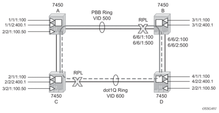
Sample Configuration:
2.6.2. Ethernet Ring Sub-Rings
Ethernet Sub-Rings offer a dual redundant way to interconnect rings. The router supports Sub-Rings connected to major rings and a sub-ring connected to a VPLS (LDP based) for access rings support in VPLS networks. Figure 25 illustrates a Major Ring and Sub-Ring scenario. In this scenario, any link can fail in either ring (ERP1 or ERP2) and each ring is protected. Furthermore, the sub ring (ERP2) relies on the major Ring (ERP1) as part of its protection for the traffic from C and D. The nodes C and D are configured as inter connection nodes.
Figure 25: 0-4 G.8032 Sub-Ring
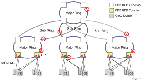
Sub-Rings and Major Rings run similar state machines for the ring logic, however there are some differences. When Sub-Rings protect a link, the flush messages are propagated to the major ring. (A special configuration allows control of this option on the router.) When major rings change topology, the flush is propagated around the major ring and does not continue to any sub-rings. The reason for this is that Major Rings are completely connected but Sub-Rings are dependent on another ring or network for full connectivity. The topology changes need to be propagated to the other ring or network usually. Sub-Rings offer the same capabilities as major rings in terms of control and data so that all link resource may be utilized.
2.6.2.1. Virtual and Non-Virtual Channel
The 7450 ESS, 7750 SR, and 7950 XRS support both the virtual channel and non-virtual channel for sub-ring control communication. In the virtual channel mode, a dedicated VID, other than the major ring RAPs control channel is configured as a data instance on the major ring. This allows the sub-ring control messages and state machine logic to behave similar to a major ring. In the non-virtual channel mode, the sub-ring is only connected by the RAPs control channels on the sub-ring itself. This mode offers slightly less redundancy in the RAPs messaging than the virtual channel mode since sub-ring RAPs messages are not propagated across the major ring. When non-virtual link is configured, the protocol allows RPL messages over the sub-ring blocked link.
Figure 26: 0-5 Sub-Ring Configuration Example
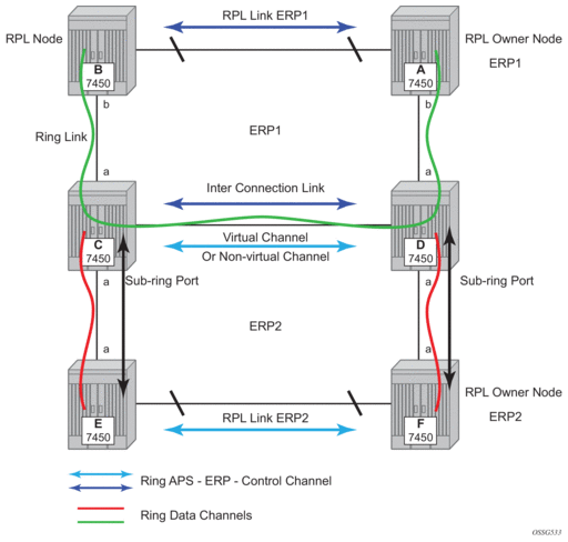
Sub-ring configuration is similar to major ring configuration and consists of three parts: Ethernet-ring instance configuration, control VPLS configuration, and data VPLS configuration (data instance or data channel). The Ethernet-ring configuration of a sub-ring is tied to a major ring and only one path is allowed.
| Note: A split horizon group is mandatory to ensure that Sub-Ring control messages from the major ring are only passed to the sub-ring control. |
As with a major ring, the forwarding of CCMs and G.8032 R-APS messages continues in the control VPLS even if the service or its SAPs are administratively shut down. The Ethernet ring instance can be shut down if it is desired to stop the operation of the ring on a node.
The data VPLS can be configured on the major ring, and in the example, shares the same VID (SAP encapsulation) on both the major ring and the sub-ring to keep data on the same VLAN ID everywhere.
| Note: Like other services in the router, the encapsulation VID is controlled by SAP configuration and the association to the controlling ring is by the Ethernet-ring, ring-id. |
The following illustrates a sample sub-ring configuration on Node C:
If the sub-ring had been configured as a non-virtual-link, the sub-ring configuration above and on all the other sub-ring nodes for this sub-ring would become:
If the sub-ring had been configured as a non-virtual-link, the configuration above would then become:
The 7450 ESS, 7750 SR, and 7950 XRS allow for a special configuration of the non-virtual link sub-ring that can be homed to a VPLS service illustrated in Figure 27. This is an economical way to have a redundant ring connection to a VPLS service. This is currently supported only for dot1Q and QinQ sub-rings and only on LDP based VPLS. The primary application for this is access rings that require resiliency. This configuration shows the configuration for a sub-ring at an interconnection node without a virtual channel and interconnected to a VPLS. A VPLS service 1 is used to terminate the ring control. The Ethernet ring data SAP appears in the associated LDP based VPLS service 5.
Figure 27: 0-6 Sub-Ring Homed to VPLS
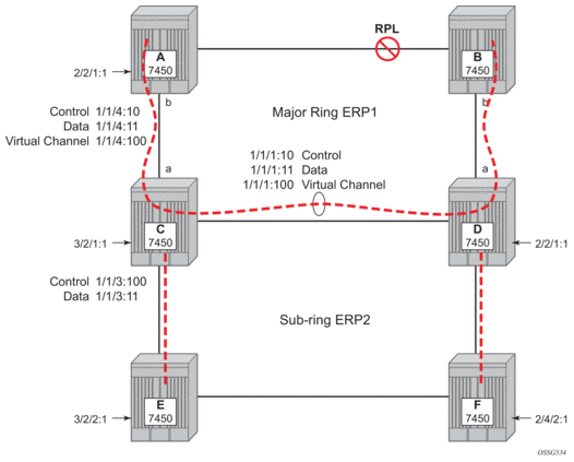
The following is a sample sub-ring configuration for VPLS (at PE1):
Ethernet-rings and sub-rings offer a way to build a scalable resilient Ethernet transport network. Figure 28 illustrates a hierarchical ring network using PBB where dual homed services are connected to a PBB based Ethernet ring network.
Figure 28: 0-7 Multi Ring Hierarchy
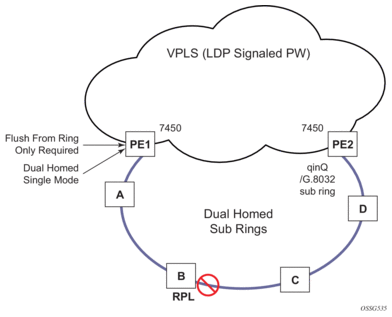
The major rings are connected by sub-rings to the top level major ring. These sub-rings require virtual channel and will not work with non-virtual channel. Ring flushing is contained to major rings, or in the case of a sub-ring link or node failure, to the sub-ring and the directly attached major rings.
2.6.2.2. LAG Support
Ethernet-rings support LAG on Ethernet rings SAPs. However, the use of LAG impact the response time for resiliency. In many cases, the use of multiple ring instances each on a single link may be more suitable from a resiliency and QoS standpoint than using LAG on Ethernet rings in a given topology. If sub 100ms response is not required, LAG is an option for Ethernet-rings.
2.6.3. OAM Considerations
Ethernet CFM is enabled by configuring MEPs on each individual path under an Ethernet ring. Only down MEPs can be configured on each of them and optionally, CCM sessions can be enabled to monitor the liveliness of the path using interval of 10 or 100 msec. Different CCM intervals can be supported on the path a and path b in an Ethernet ring. CFM is optional if hardware supports Loss of Signal (LOS) for example, which is controlled by configuring no-ccm-enable.
Up MEPs on service SAPs which multicast into the service and monitor the active path may be used to monitor services.
When Ethernet ring is configured on two ports located on different cards, the SAP queues and virtual schedulers will be created with the actual parameters on each card.
Ethernet ring CC messages transmitted over the SAP queues using the default egress QoS policy will use NC (network class) as a forwarding class. If user traffic is assigned to the NC forwarding class, it will compete for the same bandwidth resources with the Ethernet CCMs. As CCM loss could lead to unnecessary switching of the Ethernet ring, congestion of the queues associated with the NC traffic should be avoided. The operator must configure different QoS Policies to avoid congestion for the CCM forwarding class by controlling the amount of traffic assigned into the corresponding queue.
Details of the Ethernet ring applicability in the services solution can be found in the respective sections of the 7450 ESS, 7750 SR, 7950 XRS, and VSR Layer 2 Services and EVPN Guide: VLL, VPLS, PBB, and EVPN.
2.6.4. Support Service and Solution Combinations
The Ethernet rings are supported Layer 2 service, VPLS, I-VPLS, R-VPLS and B-VPLS instances. The following considerations apply:
- Only ports in access mode can be configured as Ethernet-ring paths. The ring ports can be located on the same or different media adapter cards.
- Dot1q and QinQ ports are supported as Ethernet-ring path members.
- A mix of regular and multiple Ethernet-ring SAPs and pseudowires can be configured in the same services.
2.7. Internal Objects Created for L2TP and NAT
Some services such as L2TP LNS (L2TP Network Server) and NAT (Network Address Translation) automatically create service objects for internal use. In particular, an IES service with ID 2147483648 is created. In that service, or in configured VPRN services, service objects such as interfaces, SAPs and related objects can be automatically created for internal use.
Named objects reserved for internal use have a name that starts with “_tmnx_”. Objects with a numeric identifier created for internal use have an identifier from a reserved range.
The general rules for objects reserved for internal use:
- Will appear in CLI show commands and MIB walks output;
- Will appear in the output of info detail commands but will never be in the output of admin save [detail].
It may be possible to enter the CLI node of such an object, but it is not possible to change anything. It may also be possible to set the value of one of its objects to the current value with SNMP, but it will never be possible to change any value.
2.8. Ethernet Unnumbered Interfaces
The ability to configure Ethernet Unnumbered interfaces has been added to support some service types for IPv4. The unnumbered interface capability has been available for other interface types on SR OS. Unnumbered Ethernet allows point-to-point interfaces to borrow the address from other interfaces such as system or loopback interfaces.
This feature enables unnumbered interfaces for some routing protocols (IS-IS and OSPF). Support for routing is dependent on the respective routing protocol and service. This feature also adds support for both dynamic and static ARP for unnumbered Ethernet interfaces to allow interworking with unnumbered interfaces that may not support dynamic ARP.
The use of unnumbered interface has no effect on IPv6 routes but the unnumbered command must only be used in cases where IPv4 is active (IPv4 only and mixed IPv4/IPv6 environments). When using an unnumbered interface for IPv4, the loopback address used for the unnumbered interface must have IPv4 address. Also, interface type for the unnumbered interface will automatically be point-to-point.
2.9. ECMP and Weighted ECMP for Services Using RSVP and SR-TE LSPs
ECMP over MPLS LSPs refers to spraying packets across multiple named RSVP and SR-TE LSPs within the same ECMP set. The ECMP-like spraying consists of hashing the relevant fields in the header of a labeled packet and selecting the next-hop tunnel based on the modulo operation of the output of the hash and the number of ECMP tunnels. Only LSPs with the same lowest LSP metric can be part of the ECMP set.
In weighted ECMP, the load-balancing weight of the LSP is normalized by the system and then used to bias the amount of traffic forwarded over each LSP. The weight of the LSP is configured using the config>router>mpls>lsp>load-balancing-weight weight and config>router>mpls>lsp-template>load-balancing-weight weight commands.
If one or more LSPs in the ECMP set do not have load-balancing-weight configured, and the ECMP is set to a specific next hop, regular ECMP spraying is used.
Weighted ECMP is supported for VPRN Layer 3 services. Refer to the 7450 ESS, 7750 SR, 7950 XRS, and VSR Layer 3 Services Guide: IES and VPRN for more information.
Weighted ECMP is supported for the following Layer 2 services over RSVP-TE tunnels:
- Epipe VLLs
- Ipipe VLLs
- LDP VPLS
- BGP-AD VPLS with provisioned SDPs
Class Based Forwarding (CBF) and weighted ECMP are mutually exclusive for VLL and VPLS services.
For services that use an explicitly configured SDP, weighted ECMP is configured under the SDP used by the service with the config>service>sdp>weighted-ecmp command. By default, weighted ECMP is disabled.
For VLL and VPLS services, when a service uses a provisioned SDP on which weighted ECMP is configured, a path is selected based on the configured hash. Paths are then load-balanced across LSPs within an SDP according to the normalized LSP weights. Additional fields may be taken into account for VPLS services based on the commands in the config>service>load-balancing context.
2.10. Network Group Encryption (NGE)
This section provides information to configure network group encryption (NGE) on the VSR.
2.10.1. NGE Overview
The network group encryption (NGE) feature enables end-to-end encryption of MPLS services, Layer 3 user traffic, and IP/MPLS control traffic. NGE is an encryption method that uses a group-based keying security architecture, which removes the need to configure individual encryption tunnels to achieve network-wide encryption.
NGE relies on the NSP NFM-P to manage the network and apply encryption to specific MPLS services, Layer 3 user traffic, or control plane traffic depending on the security requirements of the network. Operators designate traffic types that require added security and then apply NGE to those traffic types using the NSP NFM-P. The NSP NFM-P also acts as the network-wide NGE key manager, downloading encryption and authentication keys to nodes and performing hitless rekeying of the network at operator-defined intervals. For more information about managing NGE within a network, see the NSP NFM-P User Guide.
Figure 29 shows an NGE network with NSP NFM-P services, control plane configuration, and key management.
Figure 29: NGE Network with NSP NFM-P Management
NGE provides three main types of encryption to secure an IP/MPLS network:
- SDP encryption — MPLS user plane encryption enabled on MPLS tunnels (SDPs) supporting VPRN or IES services using spoke SDPs, VPLS using spoke or mesh SDPs, routed VPLS into VPRN, Epipes, and Cpipes
- VPRN encryption — MP-BGP-based VPRN-level encryption using auto-bind of LDP, GRE, MPLSoUDP, RSVP-TE, and MPLS (LDP or RSVP-TE) tunnels
- router interface — Layer 3 user plane and control plane encryption
- WLAN-GW group interface — L2oMPLSoGRE level encryption from WLAN access points (APs) that support NGE
| Note: Refer to the 7450 ESS, 7750 SR, 7950 XRS, and VSR Router Configuration Guide for information about configuring NGE on router interfaces. Refer to the 7450 ESS, 7750 SR, and VSR Triple Play Service Delivery Architecture Guide for information about configuring group encryption on the WLAN-GW group interface. |
NGE is supported on the following platforms:
- VSR-I
- VSR-a
WLAN-GW group interfaces enabled with NGE is further supported on the following platforms:
- 7750 SR-7
- 7750 SR-12
- 7750 SR-12e
- 7750 SR-1e
- 7750 SR-2e
- 7750 SR-3e
2.10.1.1. NGE Key Groups and Encryption Partitions
NGE allows a tiered approach to managing encryption keys in a network using key groups by configuring services or router interfaces to use specific key groups, depending on security policies for the service and network topology.
Figure 30 shows a typical application of NGE key-group partitioning in which there are several critical levels (tiers) of security that need to be considered. In this example, the protection of Distribution Automation and Field Area Network (DA/FAN) equipment are less critical than the Transmission or Distribution Substation network equipment. Ensure that nodes more at risk of a security breach do not contain more critical information than is necessary. Therefore, encryption keys for the sensitive portions of the network (such as control center traffic) should not be available on nodes that are at risk. The NGE feature enables operators to partition and distribute encryption keys among different services, NGE domains, or nodal groups in a network. NGE partitions are enabled by configuring different key groups per security partition and applying those key groups as needed.
Figure 30: Key-Group Partitioning
Another application of key-group partitioning allows different parts of an organization to have their own method of end-to-end communication without the need to share encryption keys between each organization. If two partitions need to communicate between themselves, gateway nodes configured with both key groups allow inter-organization traffic flows between the key group partitions as needed.
2.10.1.2. Network Services Platform Management
The NGE feature is tightly integrated with the NSP NFM-P. The following functions are provided by the NSP NFM-P :
- managing and synchronizing encryption and authentication keys within key groups on a network-wide basis
- configuring NGE on MPLS services and managing associated key groups
- configuring NGE on router interfaces and managing associated key groups
- coordinating network-wide rekeying of key groups
The NSP NFM-P acts as the key manager for NGE-enabled nodes and allocates the keys in key groups that are used to perform encryption and authentication. The NSP NFM-P ensures that all nodes in a key group are kept in synchronization and that only the key groups that are relevant to the associated nodes are downloaded with key information.
The NSP NFM-P performs network-wide hitless rekeying for each key group at the rekeying interval specified by the operator. Different key groups can be rekeyed at different times if desired, or all key groups can be rekeyed network-wide at the same time.
For more information on NSP NFM-P management, refer to the “Service Management” section in the NSP NFM-P User Guide.
2.10.2. Key Groups
Users can partition the network based on security requirements by organizing encryption keys into distinct key groups. A key group contains the following elements:
- an encryption algorithm—see Key Group Algorithms
- an authentication algorithm—see Key Group Algorithms
- a list of security associations (SAs)—see Security Associations
- an active outbound SA—see Active Outbound SA
Figure 31 illustrates the use of key groups (KGs), SAs, and security parameter indices (SPIs). The VSR-1 and VSR-2 both have the same set of key groups configured. One path uses key group 1 (KG1) and the other uses key group 2 (KG2). Each key group contains the elements listed above. KG1 has four live keys, SPI_1 through SPI_4, and SPI_3 is the active outbound SA. The active outbound SA is identified by its SPI, and this SPI is embedded in the NGE packet.
Each SA listed in a key group, indexed by an SPI, specifies a single key for encryption and a single key for authentication. Packets transmitted or received that reference a particular SPI use the keys in the SA for that SPI when performing encryption and authentication.
Before enabling encryption, key groups must be configured on the node. Only after a key group is configured can it be assigned to an SDP or VPRN services.
Figure 31: Key Groups and a Typical NGE Packet
2.10.2.1. Key Group Algorithms
All SAs configured in a key group share the same encryption algorithm and the same authentication algorithm. The size and values required by a particular key depend on the requirements of the algorithms selected (see lists below). One encryption algorithm and one authentication algorithm must be selected per key group.
Encryption algorithms available per key group include:
- AES128 (a 128-bit key, requiring a 32-digit ASCII hexadecimal string)
- AES256 (a 256-bit key, requiring a 64-digit ASCII hexadecimal string)
Authentication algorithms available per key group include:
- HMAC-SHA-256 (a 256-bit key, requiring a 64-digit ASCII hexadecimal string)
- HMAC-SHA-512 (a 512-bit key, requiring a 128-digit ASCII hexadecimal string)
Encryption and authentication strengths can be mixed depending on the requirements of the application. For example, 256-bit strength encryption can be used with 512-bit strength authentication.
The configured algorithms cannot be changed when there is an existing SA configured for the key group. All SAs in a key group must be deleted before a key group algorithm can be modified.
Key values are not visible in CLI or retrievable using SNMP. Each node calculates a 32-bit CRC checksum for the keys configured against the SPI. The CRC can be displayed in the CLI or read by SNMP. The purpose of the CRC is to provide a tool to check consistency between nodes, thereby verifying that each node is set with the same key values while keeping the actual key values hidden.
2.10.2.1.1. Encapsulating Security Payload
The NGE feature uses the Encapsulating Security Payload (ESP) protocol according to IETF RFC 4303. ESP maintains data integrity, ensuring privacy and confidentiality for encrypted traffic.
The ESP protocol used by NGE relies on symmetric ciphers, meaning that the same key is used for encryption and decryption. The NGE node supports Cipher Block Chaining (CBC) encryption mode. Block ciphers used by NGE include:
- AES128 with a 128-bit key using 128-bit blocks
- AES256 with a 256-bit key using 128-bit blocks
For authentication, the integrity check value (ICV) size is as follows:
- HMAC-SHA-256 (16 bytes or 128 bits)
- HMAC-SHA-512 (32 bytes or 256 bits)
2.10.2.2. Security Associations
Each key group has a list of up to four security associations (SAs). An SA is a reference to a pair of encryption and authentication keys that are used to decrypt and authenticate packets received by the node and to encrypt packets leaving the node.
For encrypted ingress traffic, any of the four SAs in the key group can be used for decryption if there is a match between the SPI in the traffic and the SPI in the SA. For egress traffic, only one of the SAs can be used for encryption and is designated as the active outbound SA. Figure 31 illustrates these relationships.
As shown in Figure 31, each SA is referenced by an SPI value, which is included in packets during encryption and authentication. SPI values must be numerically unique throughout all SAs in all key groups. If an SPI value is configured in one key group and an attempt is made to configure the same SPI value in another key group, the configuration is blocked.
| Note: Keys are entered in clear text using the security-association command. After configuration, they are never displayed in their original, clear text form. Keys are displayed in an encrypted form, which is indicated by the system-appended crypto keyword when an info command is run. The NGE node also includes the crypto keyword with an admin>save operation so that the NGE node can decrypt the keys when reloading a configuration database. For security reasons, keys encrypted on one node are not usable on other nodes (that is, keys are not exchangeable between nodes). |
2.10.2.2.1. Active Outbound SA
The active outbound SA is specified by the SPI referencing the specific SA used to encrypt and authenticate packets egressing the node for the SDP or service using the key group. The SPI value for the active outbound SA is included in the ESP header of packets being encrypted and authenticated.
2.10.3. Services Encryption
NGE provides the ability to encrypt MPLS services using key groups that are configured against these services. These services include:
- VLL service (Epipe and Cpipe)
- VPRN service using Layer 3 spoke-SDP termination
- IES service using Layer 3 spoke-SDP termination
- VPLS service using spoke and mesh SDPs
- routed VPLS service into a VPRN or IES
- MP-BGP-based VPRNs
- L2oMPLSoGRE VLL service terminating on a WLAN-GW group interface
For services that use SDPs, all tunnels may be either MPLS LSPs (RSVP-TE, LDP, or static LSP), or GRE or MPLSoUDP tunnels.
For MP-BGP services, auto-bind-tunnel is supported using LDP, GRE, MPLSoUDP, RSVP-TE, or MPLS (LDP or RSVP-TE).
2.10.3.1. Services Encryption Overview
NGE adds a global encryption label to the label stack for encrypting MPLS services. The global encryption label must be a unique network-wide label; in other words, the same label must be used on all nodes in the network that require NGE services. The label must be configured on individual nodes before NGE can become operational on those nodes.
The global encryption label is used to identify packets that have an NGE-encrypted payload and is added to the bottom of the stack. This allows network elements such as LSRs, ABRs, ASBRs, and RRs to forward NGE packets without needing to understand NGE or to know that the contents of these MPLS packets are encrypted. Only when a destination PE receives a packet that needs to be understood at the service layer does the PE check for an encryption label, and then decrypt the packet.
After the global encryption label is set, it should not be changed. If the label must be changed without impacting traffic, all key groups in the system should first be deleted. Next, the label should be changed, and then all key groups should be reconfigured.
The NSP NFM-P helps to coordinate the distribution of the global encryption label and ensures that all nodes in the network are using the same global encryption label.
Figure 32 illustrates the NGE MPLS, GRE, or MPLSoUDP label stack.
Figure 32: NGE MPLS/GRE/MPLSoUDP Label Stack
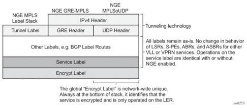
Figure 33 illustrates VPRN and PW (with control word) packet formats using NGE.
Figure 33: NGE and Packet Formats
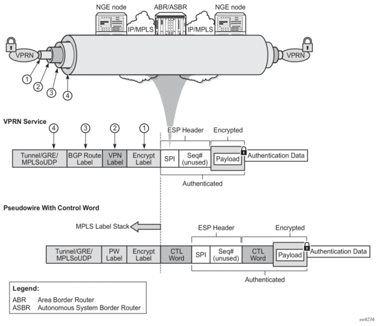
2.10.3.2. Assigning Key Groups to Services
Assigning key groups to services requires configuring an inbound and outbound key group for directional processing on a per-service basis (see Figure 34).
Figure 34: Inbound and Outbound Key-Group Assignments
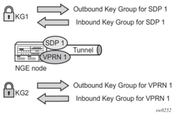
The outbound key group identifies which key group to use for traffic that egresses the node for the service. The inbound key group ensures that ingress traffic is using the correct key group for the service.
If the inbound key group is not set, the node ensures that packets are either unencrypted or are using one of the valid key groups configured in the system.
In most deployment scenarios, the inbound and outbound key groups are identical; however, it is possible to configure different key groups as the outbound and the inbound key groups, as this is not checked by the node.
Including an inbound and outbound direction when assigning key groups to services allows users to:
- gracefully enable and disable NGE for services
- move services from one key-group domain to another domain without halting encryption
The NGE feature makes use of the NSP NFM-P to help manage the assignment of key groups to services on a network-wide basis. Refer to the NSP NFM-P User Guide for more information.
2.10.3.3. Pseudowire Switching for NGE Traffic
For VLL services, the NGE node supports PW switching of encrypted traffic from one PW to another. There are three scenarios that are supported with regard to PW switching of traffic:
- PW switch using the same key groupWhen a PW is using an encrypted SDP, the PW may be switched to another PW that is also using an encrypted SDP, where both SDPs are in the same key group. In this case, to perform the PW switch, the NGE node leaves the encrypted payload unchanged and swaps the labels as needed for passing traffic between PWs.
- PW switch using different key groupsWhen a PW is using an encrypted SDP, the PW may be switched to another PW that is also using an encrypted SDP, where both SDPs are in different key groups. In this case, the NGE node decrypts the traffic from the first SDP by using the configured key group for that SDP, and then re-encrypts the traffic by using the egress SDP's key group egress SPI ID.
- PW switch between an encrypted and unencrypted PWWhen traffic is switched from an encrypted PW to an unencrypted PW, the traffic is decrypted before it is sent. The converse occurs in the reverse direction (that is, traffic from an unencrypted PW to an encrypted PW gets encrypted before it is sent).
Refer to “Pseudowire Switching” in the 7450 ESS, 7750 SR, 7950 XRS, and VSR OAM and Diagnostics Guide for more information.
2.10.3.4. Pseudowire Control Word for NGE Traffic
The control word is a configurable option for PWs and is included in PW packets when it is configured. When control-word is enabled and NGE is used, the datapath creates two copies of the CW. One CW is both encrypted and authenticated, and is inserted after the ESP header. The other CW is not encrypted (clear form) and is inserted before the ESP header.
For cases where PW switching is configured, the NGE node ensures—in the CLI and with SNMP—that both segments of the PW have consistent configuration of the control word when encryption is being used.
2.10.3.5. WLAN-GW Encryption
NGE is supported on the WLAN-GW to provide encryption of traffic to and from WLAN APs that support NGE, such as the 7705 SAR-Hm. As shown in Figure 35, the application uses Epipe pseudowire services, as described in Pseudowire Switching for NGE Traffic and Pseudowire Control Word for NGE Traffic, with L2oMPLSoGRE transport and NGE applied to the GRE-SDP.
Figure 35: Terminating NGE-Protected WLAN AP Traffic Destined to the WLAN-GW
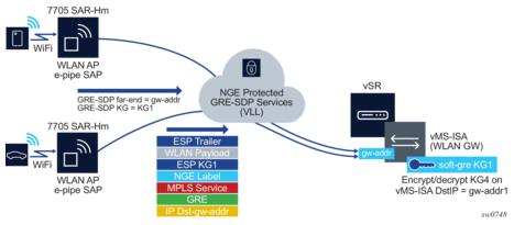
In Figure 35, the same key-group, KG1, is configured on:
- the WLAN-GW gw-address under the IES or VPRN soft-GRE group interface for the vMS-ISA
- the GRE SDPs that are bound to any WLAN AP Epipes that are terminating soft-GRE services on the WLAN-GW group interface.
Traffic from an authenticated user on the SAR-Hm WLAN AP is encrypted and an NGE label is added to the packet after the Epipe service label. The packet format is shown in Figure 35.
The WLAN-GW group interface is configured with the same inbound and outbound key-group as the GRE-SDP used for the Epipe from the WLAN AP. Any L2oMPLSoGRE packet received by the WLAN-GW on the NGE-enabled group interface must be encrypted with NGE per the above format. All other supported WLAN-GW packet types (that is, those not using L2oMPLSoGRE) are not impacted by the NGE configuration and can pass through the WLAN-GW without NGE (such as L2oGRE packets).
2.10.3.6. VPRN Layer 3 Spoke-SDP Encryption and MP-BGP-based VPRN Encryption Interaction
The encryption configured on an SDP used to terminate the Layer 3 spoke SDP of a VPRN always overrides any VPRN-level configuration for encryption.
- When VPRN encryption is enabled, all routes resolved using MP-BGP are encrypted or decrypted using the VPRN key group.
- When Layer 3 spoke-SDP encryption is enabled, all routes resolved using the Layer 3 interface are encrypted or decrypted using the SDP's key group.
Some examples are as follows.
- If a VPRN is enabled for encryption while a Layer 3 spoke SDP for the same VPRN is using an SDP that is not enabled for encryption, then traffic egressing the spoke SDP is not encrypted.
- If a VPRN is disabled for encryption while a Layer 3 spoke SDP for the same VPRN is using an SDP that is enabled for encryption, then traffic egressing the spoke SDP is encrypted.
- If a VPRN is enabled for encryption using key group X, while a Layer 3 spoke SDP for the same VPRN is using key group Y, then traffic egressing the spoke SDP is encrypted using key group Y.
The commands used for these scenarios are config>service>sdp>encryption-keygroup and config>service>vprn>encryption-keygroup.
2.10.3.7. NGE and RFC 3107
When RFC 3107 is enabled on the node and NGE traffic is crossing the Area Border Router (ABR) between two VPRN domains, the same key group must be used between the two domains.
| Note: It is the responsibility of the network operator to ensure key group consistency across the (ABR). |
2.10.4. NGE Packet Overhead and MTU Considerations
NGE adds overhead packets to services. Table 8 shows the additional overhead for the worst-case scenario of MPLS services encryption. Table 9 shows the additional overhead for the worst-case scenario of router interface. Additional overhead depends on which encryption and authentication algorithms are chosen.
Table 8: NGE Overhead for MPLS
Item | Number of Bytes |
Encryption label | 4 |
ESP | 24 |
ICV | 32 |
Padding | 17 |
Control word copy | 4 |
Total | 81 |
For MP-BGP-based VPRNs, the total is 77 bytes because the control word copy is not required.
Table 9: NGE Overhead for Router Interface
Item | Number of Bytes |
ESP | 24 |
ICV | 32 |
Padding | 17 |
Total | 73 |
For Layer 3 packets for router interface encryption, the total is 73 bytes because the encryption label and control word copy are not required.
The overhead values in Table 8 must be considered for services that are supported by NGE.
| Note: Currently, the port MTU has a default value of 1572 bytes. This value is too low for outbound traffic when NGE is enabled. Users must configure new MTU values to adjust for the overhead associated with NGE, as outlined in Table 10 for MPLS-based and GRE-based services. For details on configuring MTU, refer to the “MTU Configuration Guidelines” section in the 7450 ESS, 7750 SR, 7950 XRS, and VSR Interface Configuration Guide. |
The calculations in Table 10 show how NGE overhead affects SDP MTU and service MTU values for MPLS-based, GRE-based, and VPRN-based services. The calculations are with and without NGE enabled.
Table 10: Accounting for NGE Overhead SDP and Service MTU — Calculation Examples
Service Type | MTU Values With and Without NGE Enabled | |
MPLS-based services | SDP MTU (MPLS) = 1572 (network port MTU) – 14 (Ethernet header) – 4 (outer label) – 4 (inner label) = 1550 bytes (without NGE enabled) => 1469 bytes (with NGE enabled) | |
Service MTU (MPLS) considerations with NGE enabled
| ||
GRE-based services | SDP MTU (GRE) = 1572 (network port MTU) – 14 (Ethernet header) – 20 (IP header) – 4 (GRE header) – 4 (inner label) = 1530 bytes (without NGE enabled) => 1449 bytes (with NGE enabled) | |
Service MTU (GRE) considerations with NGE enabled
| ||
VPRN-based services | Each interface inherits its MTU from the SAP or spoke SDP to which it is bound and the MTU value can be manually changed using the ip-mtu command. | |
MP-BGP-based VPRN services The MTU of the egress IP interface is used. When NGE is enabled on a VPRN service, customers must account for the additional 77 bytes of overhead needed by NGE for any egress IP interface used by the VPRN service. | ||
When an unencrypted Layer 3 packet ingresses the node and routing determines that the egress interface is a router interface NGE-enabled interface, the node calculates whether the packet size will be greater than the MTU of the egress interface after the router interface NGE overhead is added. If the packet cannot be forwarded out from the network interface, an ICMP message is sent back to the sender and the packet is dropped. Users must configure new MTU values to adjust for the overhead associated with NGE.
If an IP exception ACL that matches the ingressing packet exists on the egress interface, the MTU check applied to the ingress packet includes the router interface NGE overhead. This is because the ingress interface cannot determine which IP exceptions are configured on the egress interface, and therefore the worst-case MTU check that includes the router interface NGE overhead is performed.
2.10.5. Statistics
Statistics specific to NGE are counted for the following main areas:
- key group
- SPI
- MDA
- service
2.10.6. Remote Network Monitoring Support
Remote network Monitoring (RMON) can be used in conjunction with NGE statistics to provide event and alarm reporting. This can be used by customers to detect security breaches of NGE traffic flows and provide real-time reporting of such events.
Threshold crossing alerts and alarms using RMON are supported for SNMP MIB objects, including NGE.
2.10.7. Configuration Notes
This section describes NGE configuration guidelines and caveats. For more information about configuring NGE using the NSP NFM-P, see the NSP NFM-P User Guide.
Consider the following caveats when performing NGE configuration tasks.
- The authentication and encapsulation keys must contain the exact number of hexadecimal characters required by the algorithm used. For example, using sha256 requires 64 hexadecimal characters.
- The key group bound to an SDP or service must be unbound from that SDP or service before the active outgoing SA for the key group can be removed.
- The active outgoing SA must be removed (deconfigured) before the SPI can be deleted from the SA list in the key group.
- The encryption or authentication algorithm for a key group cannot be changed if there are any SAs in the key group.
- The encryption configured on an SDP used to terminate the Layer 3 spoke SDP of a VPRN (enabled or disabled) always overrides any VPRN-level configuration for encryption. See section “VPRN Layer 3 Spoke-SDP Encryption and MP-BGP-based VPRN Encryption Interaction” in the 7450 ESS, 7750 SR, 7950 XRS, and VSR Layer 3 Services Guide: IES and VPRN for more information.
- The NSP NFM-P provides configuration parameters that are not configurable using the CLI. See Network Services Platform Management for more information.
To enable NGE for an SDP or VPRN service:
- Install the outbound direction key group on each node for the service.
- Install the inbound direction key group on each node for the service.
To enable NGE for a router interface:
- Enable group-encryption on the interface.
- Configure the outbound key group.
- Configure the inbound key group.
To change NGE from one key group to another key group for an SDP or VPRN service:
- Remove the inbound direction key group from each node for the service.
- Change the outbound direction key group on each node for the service.
- Install the new inbound direction key group on each node for the service.
To change NGE from one key group to another key group for a router interface:
- Remove the inbound key group.
- Configure the new outbound key group.
- Configure the new inbound key group.
To disable NGE for an SDP or VPRN service:
- Remove the inbound direction key group from each node providing the service.
- Remove the outbound direction key group from each node for the service.
To disable NGE for a router interface:
- Remove the inbound key group.
- Remove the outbound key group.
- Disable group encryption on the interface.
2.11. Service Creation Process Overview
Figure 36 displays the overall process to provision core and subscriber services.
Figure 36: Service Creation and Implementation Flow
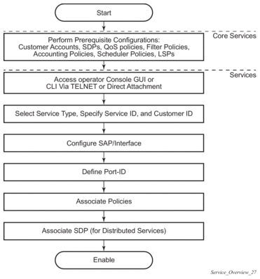
2.12. Deploying and Provisioning Services
The service model provides a logical and uniform way of constructing connectivity services. The basic steps for deploying and provisioning services can be broken down into three phases.
2.12.1. Phase 1: Core Network Construction
Before the services are provisioned, the following tasks should be completed:
- Build the IP or IP/MPLS core network.
- Configure routing protocols.
- Configure MPLS LSPs (if MPLS is used).
- Construct the core SDP service tunnel mesh for the services.
2.12.2. Phase 2: Service Administration
Perform preliminary policy and SDP configurations to control traffic flow, operator access, and to manage fault conditions and alarm messages, the following tasks should be completed:
- Configure group and user access privileges.
- Build templates for QoS, filter or accounting policies needed to support the core services.
2.12.3. Phase 3: Service Provisioning
- Provision customer account information.
- If necessary, build any customer-specific QoS, filter or accounting policies.
- Provision the services on the service edge routers by defining SAPs, binding policies to the SAPs, and then binding the service to appropriate SDPs as necessary. Refer to Configuring Customers and Configuring an SDP.
2.13. Configuration Notes
This section describes service configuration caveats.
2.13.1. General
Service provisioning tasks are typically performed prior to provisioning a subscriber service and can be logically separated into two main functional areas: core tasks and subscriber tasks.
Core tasks include the following:
- Create customer accounts
- Create template QoS, filter, scheduler, and accounting policies
- Create SDPs
Subscriber services tasks include the following:
- Create Apipe, Cpipe, Epipe, Fpipe, IES, Ipipe, VPLS or VPRN services on the 7750 SR.
- Create Epipe, IES, Ipipe, VPLS or VPRN services on the 7450 ESS or 7950 XRS.
- Bind SDPs
- Configure interfaces (where required) and SAPs
- Create exclusive QoS and filter policies