7. VSR Pseudowire Ports
This chapter provides information about Virtualized Service Router (VSR) pseudowire ports (PW ports), process overview, and implementation notes.
7.1. Flex PW Ports
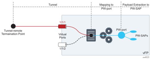
A PW port represents an extraction point of a payload carried within a tunnel. This payload is extracted onto a PW SAP within a service context (such as a Epipe, VPRN or IES). Various types of tunnels can be supported and the details of each tunnel type whose payload is terminated on a PW port is described in the following sections.
The entry point of a tunnel depends on the routing conditions in the network. To make a distinction between a PW port with a fixed connection to a physical port (a virtual port in the VSR), and a PW port that is free to switch between the ports, the latter is referred to as a Flex PW port.
A Flex PW port is bound to a list of ports, and the tunnel associated with the Flex PW port can be routed (and rerouted) through any port in that list. If traffic is re-routed through a different port due to failure in the network, the Flex PW port continues to be the terminating point of the tunnel, with minimal packet loss incurred during the switchover. See Figure 237.
Figure 237: Flex PW Port
7.1.1. PW Port List
Each port eligible to transmit traffic on a Flex PW port, must be added to a pw-port-list.
Only hybrid ports (configure port port-id ethernet mode hybrid) can be members of a PW port list.
A port used by Flex PW port can be shared with any other Layer 2 or Layer 3 service. For example, a Layer 3 interface using a regular SAP can be associated with a VPRN service, while the underlying port is also used by a Flex PW port. Another regular SAP from the same port can be associated with a VPLS or Epipe service at the same time.
Follow these rules when populating a PW port list:
- A port must be in hybrid mode before it is added to a PW port list.
- Before a port is removed from or added to a PW port list, all PW ports must be dissociated from the corresponding Epipe services (the PW ports must be unconfigured). This implies that all PW SAPs be deleted.
- Network interfaces (configured in Base routing context) can be configured only on ports that are in the PW port list.
- A port mode (access, network, or hybrid) cannot be changed while the port is in the PW port list.
From this, an operator can consider adding all ports that are in hybrid mode to a PW port list from the beginning of the system configuration. This ensures that those ports can be used by Flex PW port at any later time, independently of their current use.
7.1.2. Failover Times
Traffic loss during port switchover depends on several factors:
- Routing convergence – This depends on the number of routes in the network and the deployed routing protocol.
- The time it takes to associate PW SAPs with a new port. This action is performed within the VSR and the timing depends on the number of PW SAPs that are being moved from the old port to the new port. Note that PW SAPs are not recreated, instead the existing PW-SAPs are re-mapped to a new port.
The egress queues on the new port must be recreated. However, this does not incur additional downtime because a spare egress queue is always present on a port (referred to as a failover queue) and is used while per PW SAP egress queues are being created.
Depending on the scale and network load, downtime during a switchover can range from the sub-second range to a several seconds.
7.1.3. QoS
Egress queues are attached to the port that is used by a Flex PW port to forward traffic (a Flex PW port is bound to one of the ports in the PW port list). In similar fashion, if an egress port scheduler is used, it is attached to the same port. However, the egress port schedulers must be associated by configuration with every port in the PW port list while egress queues are instantiated only on a single port. During a port switchover, egress queues are recreated on the new port and while this is occurring, the failover queue is used to forward traffic. Each port has a single egress failover queue that is used to forward traffic while SAP or subscriber queues are being recreated during transitioning events.
On the other hand, egress port scheduler must be configured by the operator in advance on each port in the PW port list so that it can be ready to treat traffic immediately after its children queues are recreated on this port.
Policers are used on ingress and they do not need to be recreated during port switchover. Instead, they are re-mapped to a new port.
A sample QoS configuration is provided below:
- Egress port scheduler definition:port-scheduler-policy “flex" createmax-rate 1000000group "test" createexitlevel 1 rate 100000exit
- Association between the egress port scheduler and ports:configure port 1/1/1ethernetmode hybridencap-type qinqegress-scheduler-policy “flex"exitno shutdownconfigure port 1/1/2ethernetmode hybridencap-type qinqegress-scheduler-policy “flex"exitno shutdown
- Association between subscriber queues or policers and the egress port scheduler:configure qos sap-egress 2queue 1 createport-parent level 1rate 10000exitqueue 2 createport-parent level 1rate 10000exitqueue 3 createport-parent level 2rate 1000exit
- Applying queue policy to an object:Subscriber managementconfigure subscriber-mgmt sla-profile "sla-profile-1"egressqos 2exitPW SAP in a Layer 2 serviceconfigure service epipe 10sap pw-1:1.2egressqos 2exitPW SAP in a Layer 3 serviceconfigure service vprn 11interface ‘flex-int’address 1.1.1.1/24sap pw-1:1.3egressqos 2exitexitexit
7.1.4. PW Port Termination for Various Tunnel Types
The MPLS-based spoke SDP and L2oGRE-based spoke SDP tunnel types are supported on a Flex PW port.
7.1.4.1. MPLS-Based Spoke SDP
An MPLS-based spoke SDP can be rerouted between the ports defined in the PW port list and still be mapped to the same PW port based on the service label. Ethernet payload within the spoke SDP can be extracted onto a PW SAP with minimal traffic loss during port switchover.
7.1.4.1.1. Provisioning
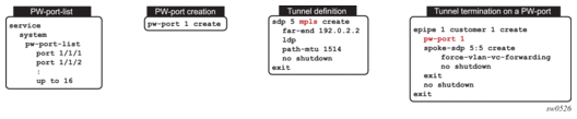
The termination of a MPLS-based spoke SDP on a Flex PW port follows the common provisioning framework:
- Creating a pw-port-list
- Adding ports that are in hybrid mode to the pw-port-list
- Creating a PW port
- Configuring a tunnel
- Terminating a tunnel on a PW port via an Epipe service. A PW port must be configured within the Epipe before a spoke SDP is added to the same Epipe.The steps for MPLS-based spoke SDP termination on a Flex PW port are displayed in Figure 238.
Figure 238: Provisioning MPLS-Based Spoke SDP Termination on a Flex PW Port
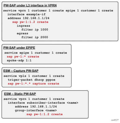
- Once a Flex PW port is associated with a tunnel, a payload from the tunnel can be extracted using service delimiting tags (Ethernet VLANs to S-tags, C-tags in the inner Ethernet header) on a PW SAP on a Layer 2 or Layer 3 service. See Figure 239
Figure 239: PW SAP Configuration Example
7.1.4.1.2. Flex PW-Port Operational State for MPLS Based Spoke SDP
The operational state of the Flex PW port is driven by the ability of the Epipe service (that ties the PW port to the spoke SDP) to forward traffic. The following events renders the PW port non-operational and triggers propagation of the PW status bits toward the remote end:
- The Epipe service is shut down. This raises the following flags on the local end:
- lacIngressFault
- lacEgressFault
- psnEgressFault
The corresponding PW status bits that are propagated to the remote end raises the counterpart flags on the remote end.
- The PW port within the Epipe service is shutdown. This raises the following flags on the local end:
- lacIngressFault
- lacEgressFault
The corresponding PW status bits that are propagated to the remote end raises the counterpart flags on the remote end.
- MTU mismatch. This raises the following flags on the local end:
- lacIngressFault
- lacEgressFault
- pwNotForwardingThe corresponding PW status bits that are propagated to the remote end raises the counterpart flags on the remote end.
In addition, PW port transitions into a non-operation state without propagating any PW status bits if the remote end cannot be reached.The operation state of the Flex PW port state can be observed through the state of the underlying tunnel and the corresponding service via the following show command:show pw-port 10 detail===============================================================================PW Port Information===============================================================================PW Port : 10Encap : dot1qIfIndex : 1526726666Description : PW PortDot1Q Ethertype : 0x8100Service Id : 10239Admin Status : upOper Status : up===============================================================================
7.1.4.1.3. Statistics
Statistics for the number of forwarded or dropped packets per octets per direction on a Flex PW port associated with a MPLS based spoke SDP are maintained per the spoke SDP. Octets field counts octets in customer frame (including customer’s Ethernet header with VLAN tags).
The following command is used to display Flex PW port statistics along with the status of the spoke SDP associated with the PW port:
7.1.4.2. L2oGRE-Based Spoke SDP
L2oGRE is supported for IPv4 and IPv6 transport with a termination IP address that must reside in the base router. Multiple L2oGRE tunnels can share the same termination IP address.
Each L2oGRE tunnel is represented by a unique pair of tunnel-end IP addresses. As the local endpoint address in VSR is usually shared between the tunnels, the tunnel far-end IP address becomes a differentiating field.
In VSR, an L2oGRE tunnel is represented by an SDP, which is then mapped as a spoke-SDP to a Flex PW port. Although it is mandatory to configure a VC-ID, in spoke-SDP the VC-ID loses its meaning due to nature of L2oGRE tunnel: no sub-tunnels based on an MLPS label can be multiplexed within the two L2oGRE endpoints.
7.1.4.2.1. Provisioning
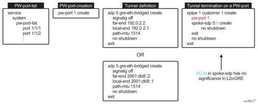
Perform the following common provisioning steps to terminate an L2oGRE tunnel on a Flex PW port:
- Create a PW port list.
- Add ports that are in hybrid mode to the PW port list.
- Create a PW port.
- Configure an L2oGRE tunnel using spoke-SDP.
- Terminate a tunnel on a PW port using an Epipe service.
A PW port must be configured within the Epipe before a spoke-SDP is added to the same Epipe.
The steps for L2oGRE termination on a Flex PW port are displayed in Figure 240.
Figure 240: Provisioning L2oGRE Spoke-SDP termination on a Flew PW Port
After a Flex PW port is associated with a tunnel, a payload from the tunnel can be extracted using service delimiting tags (such as S-tags or C-tags in the inner Ethernet header) on a PW SAP in a Layer 2 or Layer 3 service.
7.1.4.2.2. Flex PW-Port Operational State for L2oGRE-Based Spoke SDP
The operational state of the Flex PW port is determined by the ability of the stitching service (that is, the Epipe that ties the PW port to the tunnel using L2oGRE spoke-SDP) to forward traffic. This relationship can cause the stitching service’s operational status to transition to a down state in the following cases:
- the SDP far-end is not reachable
- the route-table entry is missing
- SDP is down
- the Epipe service is administratively or operationally down
7.1.4.2.3. Reassembly
Reassembly of L2oGRE over IPv4 transport is supported through a generic reassembly function that requires a vISA. Filters redirect fragmented traffic, as it enters the VSR node, to a vISA. After the traffic is reassembled in the vISA, it is re-inserted into the vFP where normal processing continues, as if the non-fragmented traffic had originally entered the node.
Perform the steps in Table 89 to configure reassembly for L2oGRE.
Table 89: Configuration Steps for L2oGRE Reassembly
Step | Sample CLI | Comments |
1. Create a NAT-group that contains MS-ISAs | configure isa nat-group 1 mda 1/1 | The reassembly function is performed in a NAT group that contains a vISA. |
2. Reference a reassembly-group that is used for traffic in the base routing context | configure router reassembly-group 1 | The reassembly-group that is used for traffic in the base routing context is identified. Upon reassembly, traffic is re-inserted in the same base routing context. The reassembly-group id corresponds to the nat-group id (in this case, the ID is 1). |
3. Identify and direct fragmented traffic to the reassembly function | configure filter ip-filter <id> default-action forward entry <id> create match protocol gre fragment true exit action reassemble exit | Fragmented GRE traffic is identified using a filter and is then redirected to the reassembly function. This filter must be applied to all ingress interfaces on which GRE traffic is expected to arrive. |