2.15. Configuring a VLL Service with CLI
This section provides information to configure Virtual Leased Line (VLL) services using the command line interface.
2.15.1. Common Configuration Tasks
This section provides a brief overview of the tasks that must be performed, and the CLI commands to configure the VLL services, as follows:
- Associate the service with a customer ID.
- Define SAP parameters:
- Optionally - configure ATM parameters on the 7750 SR
- Optionally - select egress and ingress QoS and/or scheduler policies (configured in the config>qos context).
- Optionally - select accounting policy (configured in the config>log context).
- Define spoke-SDP parameters.
- Enable the service.
2.15.2. Configuring VLL Components
This section provides VLL configuration examples for the VLL services.
2.15.2.1. Creating an Apipe Service
Use the following CLI syntax to create an Apipe service on a 7750 SR.
The following example shows the command usage to create an Apipe service.
PE router 1 (A:ALA-41):
PE router 2 (A:ALA-42):
The following example shows the Apipe service creation output.
PE Router 1 (ALA-41):
PE Router 2 (ALA-42):
2.15.2.1.1. Configuring Basic Apipe SAP Parameters
Use the following CLI syntax to configure Apipe SAP parameters.
The following example shows the command usage to create Apipe SAPs:
PE router 1 (A:ALA-41):
PE router 2 (A:ALA-42):
The following output shows the Apipe SAP configuration.
PE Router 1 (ALA-41):
PE Router 2 (ALA-42):
2.15.2.1.2. Configuring an ATM SAP in the N-to-1 Mapping of ATM VPI/VCI to ATM Pseudowire
Users can configure an ATM-cell Apipe service with a new ATM SAP type. The SAP type refers to a preconfigured ATM connection profile name.
The ATM SAP connection profile is configured with the list of discrete VPI/VCI values, as follows:
A connection profile can only be applied to a SAP that is part of an Apipe VLL service of vc-type atm-cell. The ATM SAP can be on a regular port or APS port. A connection profile can be applied to any number of ATM SAPs.
Up to a maximum of 16 discrete VPI/VCI values can be configured in a connection profile. After creation of the connection profile, the user can subsequently add, remove, or modify the VPI/VCI entries. This triggers a re-evaluation of all the ATM SAPs that are currently using that profile.
The user must also override the PW type signaled to type '0x0009 N:1 VCC cell' by using the following command:
This command is not allowed in an Apipe VLL of vc-type value atm-cell if a configured ATM SAP is not using a connection profile. Conversely, if the signaling override command is enabled, only an ATM SAP with a connection profile assigned will be allowed.
The override command is not allowed on an Apipe VLL service of vc-type value other than atm-cell. It is also not allowed on a VLL service with the vc-switching option enabled because signaling of the pseudowire FEC in a Multi-Segment Pseudowire (MS-PW) is controlled by the T-PE nodes. Therefore, for this feature to be used on a MS-PW, configure an Apipe service of vc-type atm-cell at the T-PE nodes with the signaled-vc-type-override command enabled, and configure an Apipe VLL service of vc-type atm-vcc at the S-PE node with the vc-switching option enabled.
The following are the restrictions of this feature:
- A SAP-to-SAP VLL service is not supported using ATM SAP with a connection profile assigned. The user must configure each VPI/VCI into a separate SAP and create as many Apipe VLL services of type atm-vcc as required.
- An ATM SAP with a connection profile assigned cannot be configured on a port that is part of an MC-APS protection group.
- It is strongly recommended to not apply a VCI-based QoS Filter to the ingress of an ATM SAP with a connection profile. Because the filter matches the VCI value of the first cell of a concatenated packet, the entire packet will be treated the same way based on the action of the entry of the criteria; all cells of the concatenated packet will be mapped to the same FC and profile, based on the VCI value of the first cell.
This feature is supported on the 4-port OC-3/STM-1:OC-12/STM-4 ATM MDA and on the 16-port OC-3/STM-1 ATM MDA.
2.15.2.1.3. Configuring Apipe SDP Bindings
Use the following CLI syntax to create a spoke-SDP binding with an Apipe service.
The following example displays the command usage to create Apipe spoke-SDPs:
PE router 1 (A:ALA-41):
PE router 2 (A:ALA-42):
The following output shows the Apipe spoke-SDP configurations.
PE Router 1 (ALA-41):
PE Router 2 (ALA-42):
2.15.2.2. Creating a Cpipe Service
2.15.2.2.1. Basic Configuration
Use the following CLI syntax to create a Cpipe service on a 7750 SR. A route distinguisher must be defined in order for Cpipe to be operationally active.
For the 7450 ESS platforms, the vc-switching option must be configured for Cpipe functionality, as follows:
The following displays a Cpipe service configuration example:
2.15.2.2.2. Configuration Requirements
Before a Cpipe service can be provisioned, the following tasks must be completed:
2.15.2.2.2.1. Configuring a DS1 Port
The following example shows a DS1 port configured for CES:
2.15.2.2.2.2. Configuring a Channel Group
The following example shows a DS1 channel group configured for CES:
2.15.2.2.3. Configuring Cpipe SAPs and Spoke-SDPs
The following examples show Cpipe SAP and spoke-SDP configurations:
2.15.2.3. Creating an Epipe Service
Use the following CLI syntax to create an Epipe service.
The following example shows an Epipe configuration:
2.15.2.3.1. Configuring Epipe SAP Parameters
A default QoS policy is applied to each ingress and egress SAP. Additional QoS policies can be configured in the config>qos context. Filter policies are configured in the config>filter context and explicitly applied to a SAP. There are no default filter policies.
Use the following CLI syntax to create:
The following example shows a configuration for the 7950 XRS.
The following example shows a configuration for the 7450 ESS and 7750 SR.
2.15.2.3.1.1. Local Epipe SAPs
To configure a basic local Epipe service, enter the sap sap-id command twice with different port IDs in the same service configuration.
By default, QoS policy ID 1 is applied to ingress and egress service SAPs. Existing filter policies or other existing QoS policies can be associated with service SAPs on ingress and egress ports. Table 11 shows supported SAP types.
Table 11: Supported SAP Types
Uplink Type | Svc SAP Type | Cust. VID | Access SAPs | Network SAPs |
L2 | Null-star | — | Null, dot1q * | Q.* |
L2 | Dot1q | — | Dot1q | Q.* |
L2 | Dot1q-preserve | — | Dot1q (encap = X) | Q1.Q2 (where Q2 = X) |
An existing scheduler policy can be applied to ingress and egress SAPs to be used by the SAP queues and, at egress only, policers. The schedulers comprising the policy are created when the scheduler policy is applied to the SAP. If any policers or orphaned queues (with a non-existent local scheduler defined) exist on a SAP and the policy application creates the required scheduler, the status on the queue becomes non-orphaned at this time.
Ingress and egress SAP parameters can be applied to local and distributed Epipe service SAPs.
The following example shows the SAP configurations for local Epipe service 500 on SAP 1/1/2 and SAP 1/1/3 on ALA-1:
The following example shows the local Epipe configuration:
2.15.2.3.2. Distributed Epipe SAPs
To configure a distributed Epipe service, you must configure service entities on the originating and far-end nodes. You should use the same service ID on both ends (for example, Epipe 5500 on ALA-1 and Epipe 5500 on ALA-2). The spoke-sdp sdp-id:vc-id must match on both sides. A distributed Epipe consists of two SAPs on different nodes.
By default, QoS policy ID 1 is applied to ingress and egress service SAPs. Existing filter policies or other existing QoS policies can be associated with service SAPs on ingress and egress.
An existing scheduler policy can be applied to ingress and egress SAPs to be used by the SAP queues and, at egress only, policers. The schedulers comprising the policy are created when the scheduler policy is applied to the SAP. If any policers or orphaned queues (with a non-existent local scheduler defined) exist on a SAP and the policy application creates the required scheduler, the status on the queue becomes non-orphaned at this time.
Ingress and egress SAP parameters can be applied to local and distributed Epipe service SAPs.
For SDP configuration information, refer to the 7450 ESS, 7750 SR, 7950 XRS, and VSR Services Overview Guide. For SDP binding information, see Configuring SDP Bindings.
The following example shows a configuration of a distributed service between ALA-1 and ALA-2:
The following example shows the SAP configurations for ALA-1 and ALA-2:
2.15.2.3.2.1. PBB Epipe Configuration
The following example shows the PBB Epipe configuration:
2.15.2.3.2.2. Configuring Ingress and Egress SAP Parameters
By default, QoS policy ID 1 is applied to ingress and egress service SAPs. Existing filter policies or other existing QoS policies can be associated with service SAPs on ingress and egress ports.
An existing scheduler policy can be applied to ingress and egress SAPs to be used by the SAP queues and, at egress only, policers. The schedulers comprising the policy are created when the scheduler policy is applied to the SAP. If any policers or orphaned queues (with a non-existent local scheduler defined) exist on a SAP and the policy application creates the required scheduler, the status on the queue becomes non-orphaned at this time.
Ingress and egress SAP parameters can be applied to local and distributed Epipe service SAPs.
The following example shows the SAP ingress and egress parameters:
The following example shows the Epipe SAP ingress and egress configuration:
2.15.2.3.3. Configuring SDP Bindings
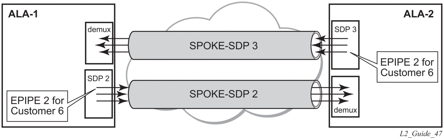
Figure 49 shows an example of a distributed Epipe service configuration between two routers, identifying the service and customer IDs, and the uni-directional SDPs required to communicate to the far-end routers.
A spoke-SDP is treated like the equivalent of a traditional bridge “port”, where flooded traffic received on the spoke-SDP is replicated on all other “ports” (other spoke and mesh SDPs or SAPs) and not transmitted on the port it was received.
Figure 49: SDPs — Uni-Directional Tunnels
Use the following CLI syntax to create a spoke-SDP binding with an Epipe service.
The following example shows the command usage to bind an Epipe service between ALA-1 and ALA-2. This example assumes the SAPs have already been configured (see Distributed Epipe SAPs).
The following example shows the SDP binding for the Epipe service between ALA-1 and ALA-2:
2.15.2.4. Creating an Fpipe Service
Use the following CLI syntax to create an Fpipe service on a 7750 SR.
The following example shows the command usage to create an Fpipe service:
PE router 1 (A:ALA-41):
PE router 2 (A:ALA-42):
The following example shows the Fpipe service creation output:
PE router 1 (A:ALA-41):
A:ALA-41>config>service# info
PE router 2 (A:ALA-42):
A:ALA-42>config>service# info
-------------------------------------------
2.15.2.4.1. Configuring Fpipe SAP Parameters
Use the following CLI syntax to configure Fpipe SAP parameters.
The following example shows the command usage to create an Fpipe SAP:
PE router 1 (A:ALA-41):
PE router 2 (A:ALA-42):
The following example shows the Fpipe SAP configuration:
PE Router 1 (ALA-41):
PE Router 2 (ALA-42):
2.15.2.4.2. Configuring Fpipe SDP Bindings
Use the following CLI syntax to create a spoke-SDP binding with an Fpipe service.
The following example shows the command usage to create an Fpipe spoke-SDP:
PE router 1 (A:ALA-41):
PE router 2 (A:ALA-42):
The following example shows the Fpipe spoke-SDP configuration:
PE Router 1 (ALA-41):
PE Router 2 (ALA-42):
2.15.2.5. Creating an Ipipe Service
Use the following CLI syntax to create an Ipipe service on a 7450 ESS or 7750 SR.
The following example shows an Ipipe configuration:
2.15.2.5.1. Configuring Ipipe SAP Parameters
The following example shows an Ipipe SAP configuration:
The following example shows a Frame Relay to Ethernet local Ipipe configuration.
The following example shows the output:
The following example shows a PPP to Ethernet local Ipipe configuration.
The following example shows the output:
2.15.2.5.2. Configuring Ipipe SDP Bindings
The following example shows an Ipipe SDP configuration:
2.15.3. Using Spoke-SDP Control Words
The control word command provides the option to add a control word as part of the packet encapsulation for PW types for which the control word is optional. These are Ethernet pseudowire (Epipe), ATM N:1 cell mode pseudowires (Apipe vc-types atm-vcc and atm-vpc), and VT pseudowire (Apipe vc-type atm-cell). The control word might be needed because when ECMP is enabled on the network, packets of a specific pseudowire may be spread over multiple ECMP paths if the hashing router mistakes the PW packet payload for an IPv4 or IPv6 packet. This occurs when the first nibble following the service label corresponds to a value of 4 or 6.
The control word negotiation procedures described in Section 6.2 of RFC 4447 are not supported and, therefore, the service will only come up if the same C-bit value is signaled in both directions. If a spoke-SDP is configured to use the control word, but the node receives a label mapping message with a C-bit clear, the node releases the label with an “Illegal C-bit” status code per Section 6.1 of RFC 4447. As soon as the user enables control of the remote peer, the remote peer withdraws its original label and sends a label mapping with the C-bit set to 1 and the VLL service is up in both nodes.
When the control word is enabled, VCCV packets also include the VCCV control word. In that case, the VCCV CC type 1 (OAM CW) is signaled in the VCCV parameter in the FEC. If the control word is disabled on the spoke-SDP, the Router Alert label is used. In that case, VCCV CC type 2 is signaled. For a multi-segment pseudowire (MS-PW), the CC type 1 is the only type supported; therefore, the control word must be enabled on the spoke-SDP to be able to use VCCV-ping and VCCV-trace.
The following example shows a spoke-SDP control word configuration:
2.15.4. Same-Fate Epipe VLANs Access Protection
The following example shows a G.8031 Ethernet tunnel for Epipe protection configuration for 7450 ESS or 7750 SR using same-fate SAPs for each Epipe access (two Ethernet member ports 1/1/1 and 2/1/1/1 are used):
2.15.5. Pseudowire Configuration Notes
The vc-switching parameter must be specified when the VLL service is created. When the vc-switching parameter is specified, you are configuring an S-PE. This is a pseudowire switching point (switching from one pseudowire to another). Therefore, you cannot add a SAP to the configuration.
The following example shows the configuration when a SAP is added to a pseudowire. The CLI generates an error response if you attempt to create a SAP. VC switching is only needed on the pseudowire at the S-PE.
Use the following CLI syntax to create pseudowire switching VLL services. These are examples only. Different routers support different pseudowire switching VLL services.
The following example shows the command usage to configure VLL pseudowire switching services:
The following example shows configurations for each service:
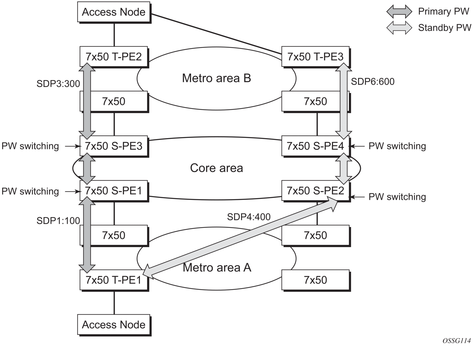
2.15.6. Configuring Two VLL Paths Terminating on T-PE2
Figure 50: VLL Resilience with Pseudowire Redundancy and Switching
T-PE1
The following shows an example of the T-PE1 configuration:
The following shows an example of the T-PE2 configuration for 7950 XRS.
T-PE2
The following shows and example of the T-PE2 configuration for 7450 ESS and 7750 SR.
T-PE2
S-PE1: Specifying the vc-switching parameter enables a VC cross-connect, so the service manager does not signal the VC label mapping immediately, but will put this into passive mode.
The following example shows the configuration:
S-PE2: Specifying the vc-switching parameter enables a VC cross-connect, so the service manager does not signal the VC label mapping immediately, but will put this into passive mode.
The following example shows the configuration:
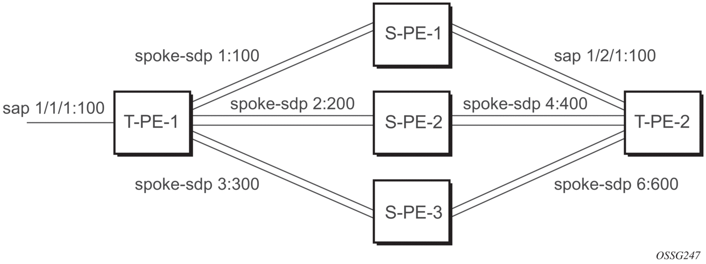
2.15.7. Configuring VLL Resilience
Figure 51 shows an example to create VLL resilience. The zero revert-time value means that the VLL path will be switched back to the primary immediately after it comes back up.
Figure 51: VLL Resilience

PE-1:
The following example shows the configuration on PE-1:
2.15.8. Configuring VLL Resilience for a Switched Pseudowire Path
Figure 52: VLL Resilience with Pseudowire Switching
T-PE-1
The following example shows the configuration on T-PE-1.
T-PE-2
The following example shows the configuration on T-PE-2.
S-PE-1
The following example shows the configuration on S-PE-1.
2.15.9. Configuring BGP Virtual Private Wire Service (VPWS)
2.15.9.1. Single-Homed BGP VPWS
Figure 53 shows an example topology for a BGP VPWS service used to create a virtual lease-line across an MPLS network between two sites: A and B.
Figure 53: Single-Homed BGP VPWS Configuration Example
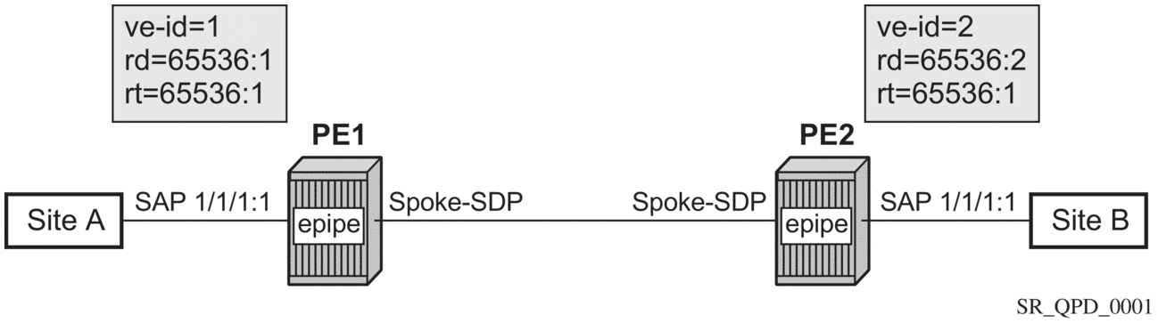
An Epipe is configured on PE1 and PE2 with BGP VPWS enabled. PE1 and PE2 are connected to site A and B, respectively, each using a SAP. The interconnection between the two PEs is achieved through a pseudowire, using Ethernet VLAN encapsulation, which is signaled using BGP VPWS over a tunnel LSP between PE1 and PE2. A MIP or MEP can be configured on a BGP VPWS SAP. However, fault propagation between a MEP and the BGP update state signaling is not supported. BGP VPWS routes are accepted only over an IBGP session.
The following example shows the BGP VPWS configuration on each PE:
The BGP-VPWS update can be shown using the following command:
2.15.9.2. Dual-Homed BGP VPWS
Single Pseudowire Example:
Figure 54 shows an example topology for a dual-homed BGP VPWS service used to create a virtual lease-line across an MPLS network between two sites: A and B. A single pseudowire is established between the designated forwarder of the dual-homed PEs and the remote PE.
Figure 54: Example of Dual-Homed BGP VPWS with Single Pseudowire
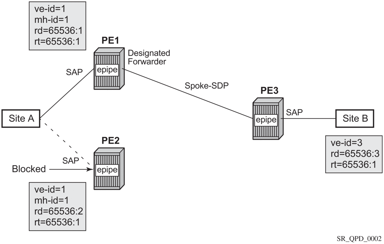
An Epipe with BGP VPWS enabled is configured on each PE. Site A is dual-homed to PE1 and PE2 with a remote PE (PE3) connected to site B; each connection uses a SAP. A single pseudowire using Ethernet Raw Mode encaps connects PE3 to PE1. The pseudowire is signaled using BGP VPWS over a tunnel LSP between the PEs.
Site A is configured on PE1 and PE2 with the BGP route selection, the site state, and the site-preference used to ensure PE1 is the designated forwarder when the network is fully operational.
The following example shows the BGP VPWS configuration on each PE.
PE1:
PE2:
PE3:
Active/Standby Pseudowire Example:
Figure 55 shows an example topology for a dual-homed BGP VPWS service used to create a virtual lease-line across an MPLS network between two sites: A and B. Two pseudowires are established between the remote PE and the dual-homed PEs. The active pseudowire used for the traffic is the one connecting the remote PE to the designated forwarder of the dual-homed PEs.
Figure 55: Example of Dual-homed BGP VPWS with Active/Standby Pseudowires
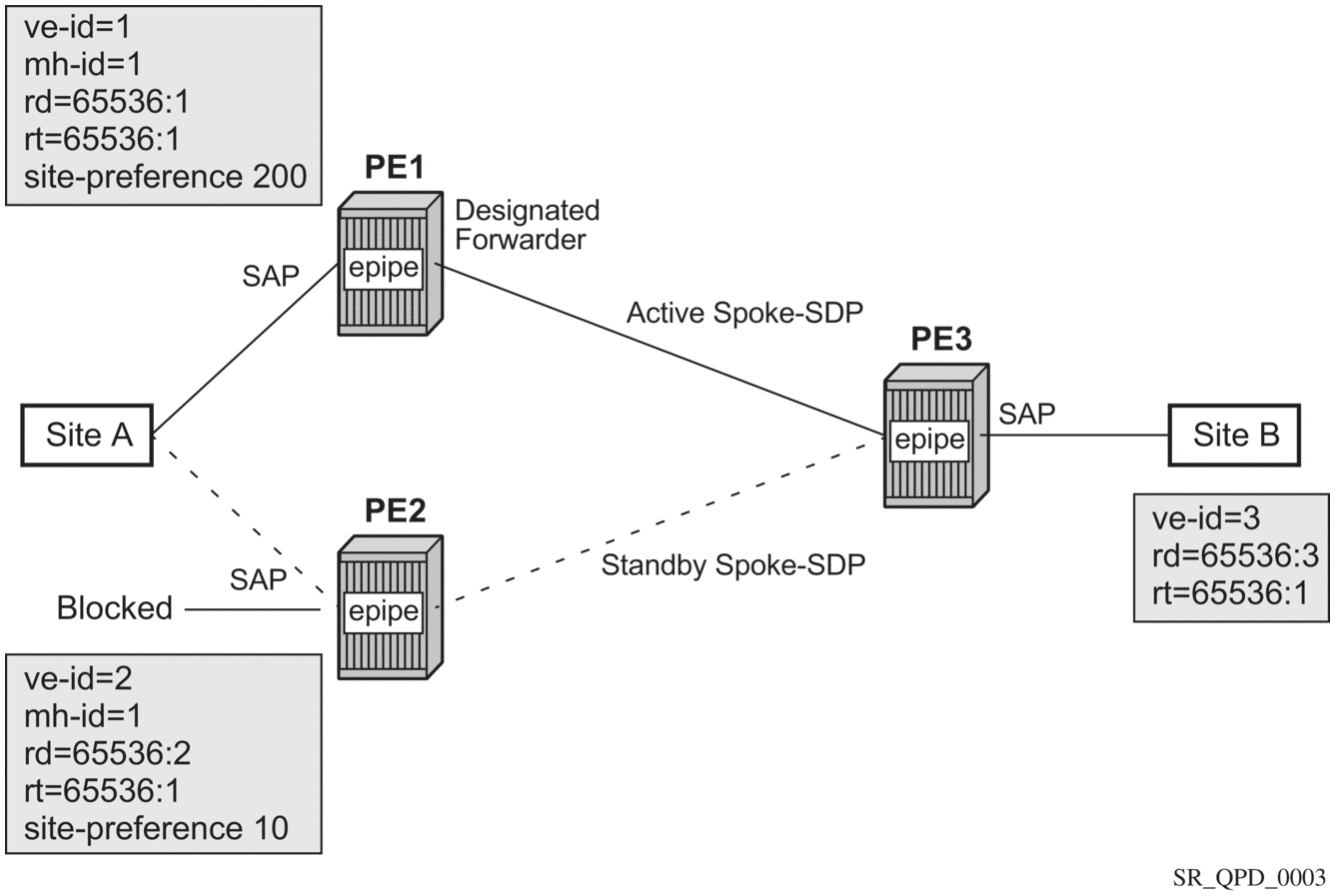
An Epipe with BGP VPWS enabled is configured on each PE. Site A is dual-homed to PE1 and PE2 with a remote PE (PE3) connected to site B; each connection uses a SAP. Active/standby pseudowires using Ethernet Raw Mode encaps connect PE3 to PE1 and PE2, respectively. The pseudowires are signaled using BGP VPWS over a tunnel LSP between the PEs.
Site A is configured on PE1 and PE2 with the site-preference set to ensure that PE1 is the designated forwarder when the network is fully operational. An endpoint is automatically created on PE3 in which the active/standby pseudowires are created.
The following example shows the BGP VPWS configuration on each PE.
PE1:
PE2:
PE3:
2.16. Service Management Tasks
This section discusses VLL service management tasks.
2.16.1. Modifying Apipe Service Parameters
The following example shows the command usage to modify Apipe parameters, supported on the 7750 SR only:
PE router 1 (A:ALA-41):
PE router 2 (A:ALA-42):
2.16.2. Disabling an Apipe Service
An Apipe service can be shut down without deleting any service parameters.
PE router 1 (A:ALA-41):
PE router 2 (A:ALA-42):
PE Router 1 (ALA-41):
PE Router 2 (ALA-42):
2.16.3. Re-enabling an Apipe Service
Use the following CLI syntax to re-enable an Apipe service that was shut down.
PE router 1 (A:ALA-41):
PE router 2 (A:ALA-42):
2.16.4. Deleting an Apipe Service
An Apipe service cannot be deleted until the SAP is shut down. If protocols and/or a spoke-SDP are defined, they must be shut down and removed from the configuration as well.
Use the following CLI syntax to delete Apipe services.
PE router 1 (A:ALA-41):
PE router 2 (A:ALA-42):
2.16.5. Modifying a Cpipe Service
The following example shows the Cpipe service configuration, supported on the 7750 SR only:
2.16.6. Deleting a Cpipe Service
A Cpipe service cannot be deleted until SAPs are shut down and deleted. If a spoke-SDP is defined, it must be shut down and removed from the configuration as well.
Use the following CLI syntax to delete a Cpipe service.
2.16.7. Modifying Epipe Service Parameters
The following example shows how to add an accounting policy to an existing SAP:
The following example shows the SAP configuration:
2.16.8. Disabling an Epipe Service
You can shut down an Epipe service without deleting the service parameters.
2.16.9. Re-enabling an Epipe Service
Use the following CLI syntax to re-enable an Epipe service that was shut down.
2.16.10. Deleting an Epipe Service
Perform the following steps prior to deleting an Epipe service:
- Shut down the SAP and SDP.
- Delete the SAP and SDP.
- Shut down the service.
Use the following CLI syntax to delete an Epipe service.
2.16.11. Modifying Fpipe Service Parameters
The following example shows the command usage to modify Fpipe parameters, supported on the 7750 SR only:
PE router 1 (A:ALA-41):
PE router 2 (A:ALA-42):
PE Router 1 (ALA-41):
PE Router 2 (ALA-42):
2.16.12. Disabling an Fpipe Service
An Fpipe service can be shut down without deleting any service parameters.
PE router 1 (A:ALA-41):
PE router 2 (A:ALA-42):
PE Router 1 (ALA-41):
PE Router 2 (ALA-42):
2.16.13. Re-enabling an Fpipe Service
Use the following CLI syntax to re-enable an Fpipe service that was shut down.
PE router 1 (A:ALA-41):
PE router 2 (A:ALA-42):
2.16.14. Deleting an Fpipe Service
An Fpipe service cannot be deleted until the SAP is shut down. If protocols and/or a spoke-SDP are defined, they must be shut down and removed from the configuration as well.
Use the following CLI syntax to delete a Fpipe service.
PE router 1 (A:ALA-41):
PE router 2 (A:ALA-42):
2.16.15. Modifying Ipipe Service Parameters
The following example shows the command usage to modify Ipipe parameters, supported on the 7450 ESS and 7750 SR only:
2.16.16. Disabling an Ipipe Service
An Ipipe service can be shut down without deleting any service parameters.
2.16.17. Re-enabling an Ipipe Service
Use the following CLI syntax to re-enable an Ipipe service that was shut down.
2.16.18. Deleting an Ipipe Service
An Ipipe service cannot be deleted until the SAP is shut down. If protocols and/or a spoke-SDP are defined, they must be shut down and removed from the configuration as well.
Use the following CLI syntax to delete an Ipipe service.