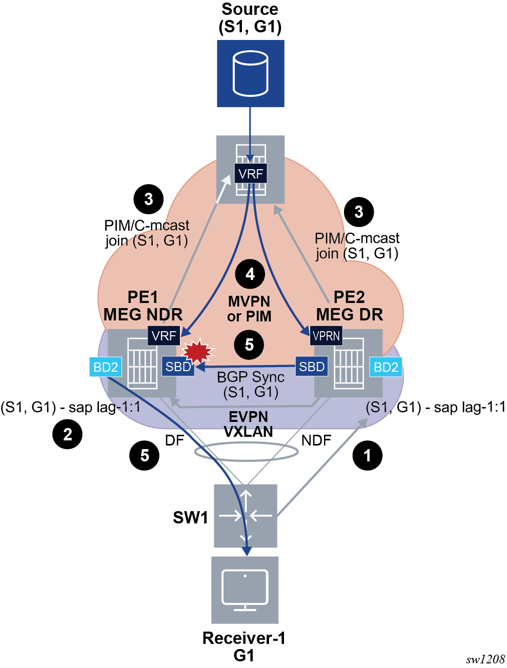
Figure 1, shows an initial situation where MEG or PEG routers PE1 and PE2 are multihomed to a local receiver in BD2. PE2 is the DR for the SBD. As both PEs are MEG or PEG for the same SBD, no EVPN destination exists between the PEs for the SBD.
The following figures shows local multihomed receivers.

The following workflow applies to the example shown in the preceding graphic.
-
PE2 learns, via IGMP/MLD, that Receiver-1 is interested in (S1,G1) and adds the ES SAP to the OIF list.
-
PE2 synchronizes the (S1,G1) state with PE1 via BGP multicast synch routes and adds the ES SAP to the OIF list.
- Both PE1 and PE2 originate an SMET(S1,G1) following normal OISM
procedures.
- Also, both PEs generate the corresponding MVPN/PIM join route for (S1,G1) because the MEG or PEG DR election only occurs in the SBD. In this case, the state is created in BD2 and both PEs send the MVPN/PIM join route.
- Also, both PEs generate the corresponding MVPN/PIM join route for (S1,G1). This is because the MEG or PEG DR election occurs only in the SBD and the state is created in BD2. Consequently, both PEs send the MVPN/PIM join route in this case.
- Step 3 causes traffic
from the source to flow to both the DF and NDF, although only the DF forwards the
traffic.
- The MEG or PEG DR and non-DR states only impact the addition of the SBD interface to the Layer 3 OIF.
- The data path extensions prevent MVPN traffic from being sent to EVPN destinations other than an SBD EVPN destination.
- PE2’s SBD is added to the Layer 3 OIF list. However, since there is no EVPN destination between the MEG/PEGs of the same SBD, multicast is not sent from PE2 to PE1.
Local-bias behavior only applies to Layer 2 multicast (BUM in general) and not to Layer 3 multicast. That is, in Figure 1, the following applies to Layer 3 multicast traffic arriving at PE1 and PE2:
- can be forwarded to single-homed and DF SAPs in BD2
- cannot be forwarded to non-DF SAPs in BD2
- cannot be forwarded to EVPN destinations in BD2, in accordance with the OISM rules