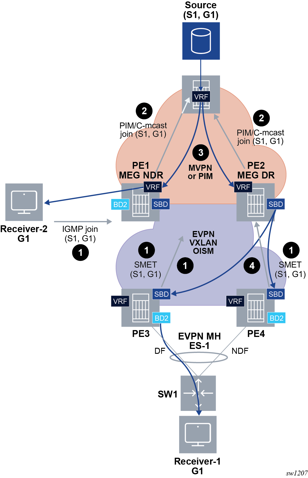
Figure 1 shows an initial situation where PE1 and PE2 are MEG/PEGs and PE2 is elected as the MEG or PEG DR. PE1 and PE2 do not have an EVPN destination between their SBDs.
The following shows a local single-homed receiver.

The following workflow applies to the example shown in the preceding graphic.
-
PE1 learns via IGMP/MLD that Receiver-2 is interested in (S1,G1).
As shown in Figure 1, Receiver-1, which is connected to a remote OISM non-MEG PE, issues an IGMP join for the same group. This triggers the corresponding SMET route from PE3 and PE4.
-
PE1 determines from its route table that there is a route to S1 via IP-VPN.
PE1 originates an MVPN C-multicast source tree join (S,G) route or a PIM (S,G) join, via normal MVPN or PIM procedures.
- PE1 adds the MVPN tunnel or PIM interface as the Layer 3 IIF. The BD2 IRB is added to the Layer 3 OIF list.
- PE1 also issues an SMET route as usual.
- Since PE2 is the SBD’s MEG DR, PE2 also sends a PIM/C-multicast join route upon receiving the SMET route from PE3 and PE4.
- PE1 or PE2 receives the multicast traffic from the appropriate tunnel or interface,
and passes RPF check. PE1 sends multicast down the BD2 IRB to the receiver. Since
PE1 is non-DR for the SBD, the SBD IRB is not in the Layer 3 OIF
list.
PE2’s SBD does not send the multicast flow to PE1, because there are no EVPN destinations between MEG or PEG PEs of the same SBD.
- Only PE2, the SBD’s MEG or PEG DR, sends the multicast down the SBD’s IRB to the remote OISM PEs and regular OISM forwarding follows on PE3 and PE4.