Segment Routing steers packets by encoding the packet-processing instructions for each intermediate and destination router directly in the packet header.
The datapath pushes a list of instructions in the form of Segment Identifiers (SIDs) onto the packet, to forward the payload packet directly to the destination using the shortest path or using source routing via one or more transit routers. Each router that terminates a SID in the segment list performs the instructions related to that SID.
Segment Routing standards specify the following two methods for programming the datapath of the encapsulated packet:
- Segment Routing MPLS (SR-MPLS) — The SID is encoded in 32 bits and programmed as an MPLS label; provides a tunnel to both IPv4 and IPv6 destinations. See Segment routing with MPLS data plane (SR-MPLS).
- Segment Routing IPv6 (SRv6) — The SID is encoded in 128 bits and programmed as an IPv6 address; provides a tunnel to IPv6 destinations
SRv6 datapath encapsulation models each SID using a 128-bit address. In shortest path routing, the destination SID is encoded in the Destination Address (DA) field of the outer IPv6 header. In source routing, the SIDs of the nodes the packet must visit are encoded as a SID list in a Segment Routing Header (SRH) that is a new type of routing header compliant with RFC 8200. The next SID in a segment list to which the packet is to be forwarded is copied from the SRH into the DA field of the outer IPv6 header.
SRv6 provides more than IPv6 transport with shortest path and source-routing capabilities; it provides a framework for programmability of IPv6 networks that takes advantage of the large IPv6 address space.
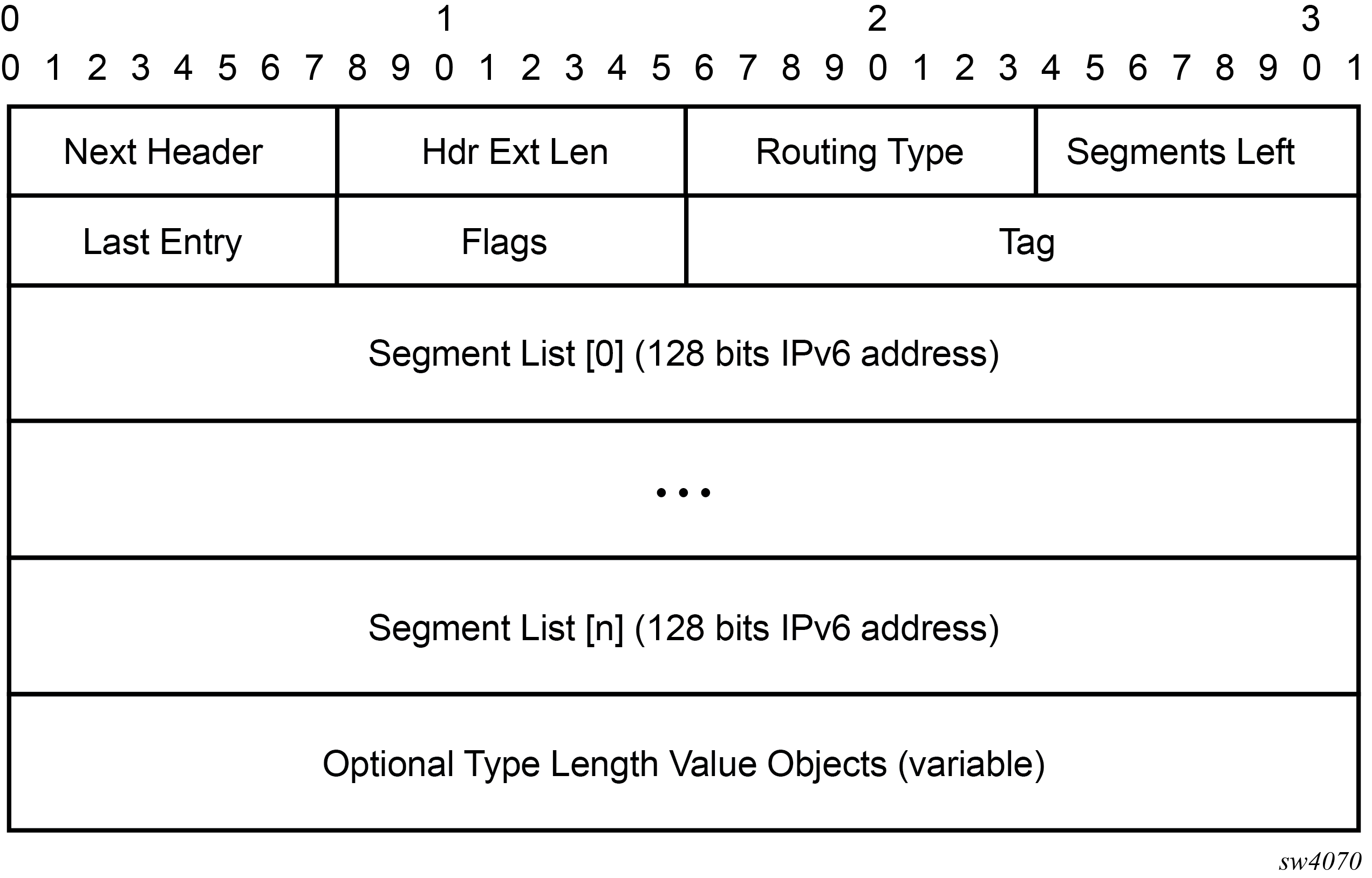
Figure 1 shows the SRv6 SRH format and fields (excerpt from RFC 8986).
| Field name | Description |
|---|---|
|
Next Header |
Defined in RFC8200, Section 4.4 |
|
Hdr Ext Len |
Defined in RFC8200, Section 4.4 |
|
Routing Type |
4 |
|
Segments Left |
Defined in RFC8200, Section 4.4 |
|
Last Entry |
Contains the index (zero based), in the Segment List, of the last element of the Segment List |
|
Flags |
RFC8754, Section 8.1 creates an IANA registry for new flags to be defined. The following flags are defined, as shown in Figure - TBD |
|
Tag |
Tag a packet as part of a class or group of packets; for example, packets sharing the same set of properties. When Tag is not used at the source, it must be set to zero on transmission. When Tag is not used during SRH processing, it is ignored. Tag is not used when processing the SID; as defined in RFC8754, Section 4.3.1. It may be used when processing other SIDs that are not defined in this document. The allocation and use of tag is outside the scope of this document. |
|
Segment List[0..n] |
128-bit IPv6 addresses representing the nth segment in the Segment List. The Segment List is encoded starting from the last segment of the SR policy. That is, the first element of the Segment List (Segment List[0]) contains the last segment of the SR policy, the second element contains the penultimate segment of the SR policy, and so on. |
|
TLV |
Type Length Value (TLV); see RFC8754, Section 2.1, and Figure 3. |

| Flag | Description |
|---|---|
|
U |
Unused and for future use. Must be 0 on transmission and ignored on receipt. |
Figure 3 shows the SRv6 Segment Identifier (SID) encoding format and fields.
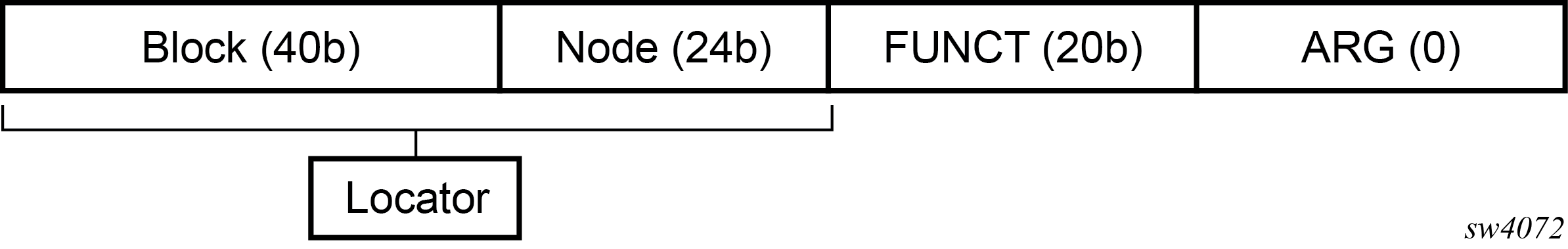
The 128-bit address of an SRv6 SID is split into a three-field structure: {LOCATOR:FUNCTION:ARGUMENT). The size of these fields is configurable. This structure is used to encode both the transport, or reachability, information in the LOCATOR field, and SID function information in the FUNCTION field.
- LOCATOR field — encodes the transport or reachability information
- FUNCTION field — encodes the node SID function (End SID), an adjacency SID function (End.X SID), or a service function that is the equivalent of a service label in SR-MPLS
- ARGUMENT field — can be used to carry limited service or application metadata; typical use is to encode a value that identifies the source Ethernet Segment for EVPN services that require multi-homing or Etree procedures
Figure 4 shows the operation of the data and control planes when an IP-VPN route is resolved to an SRv6 tunnel.
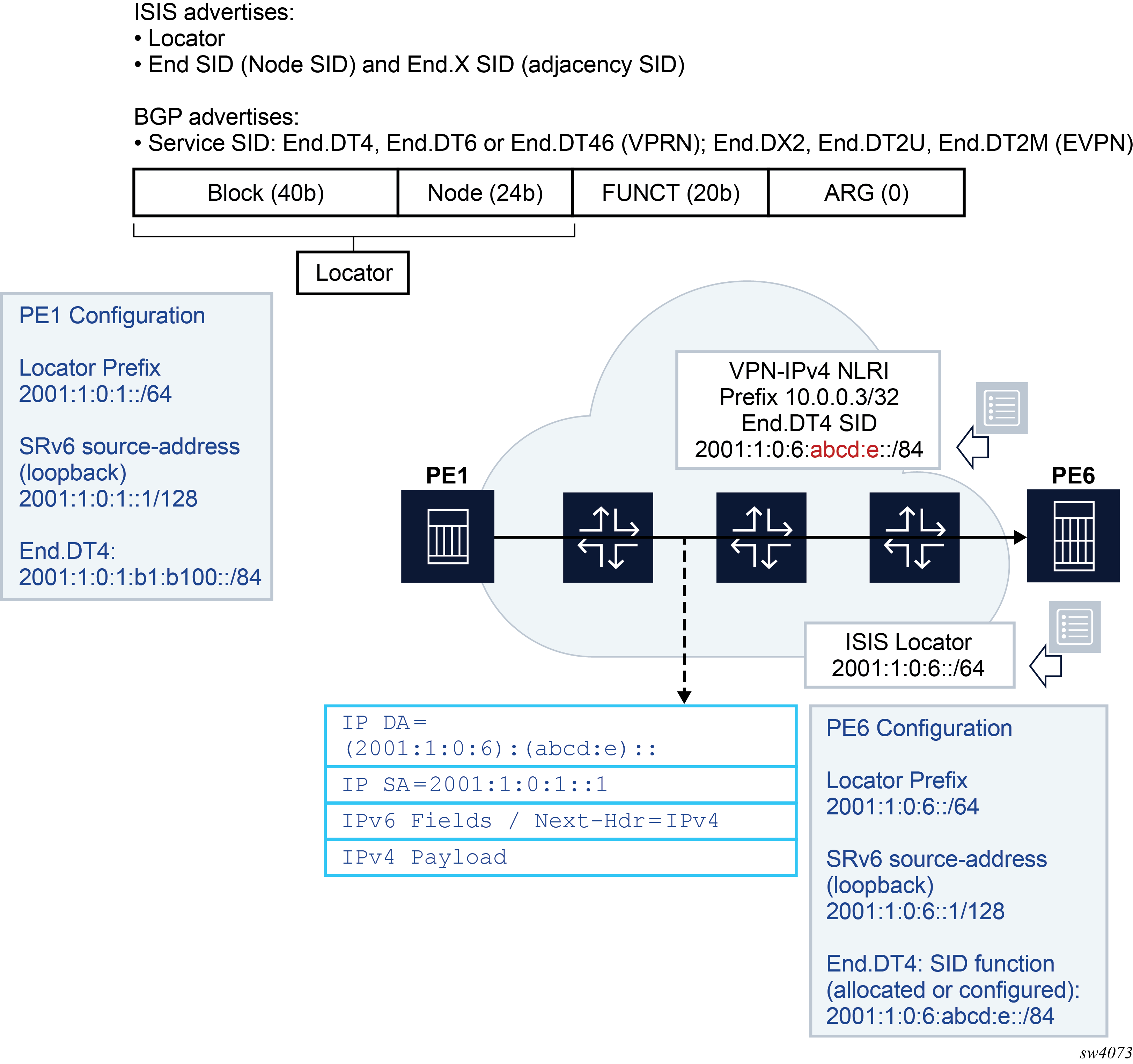
The PE6 egress router advertises in IS-IS the locator route that contains its locator prefix and optionally a local node SID (End). It also advertises the SID of each adjacency (End.X) to its IS-IS neighbors.
The locator prefix provides the route to reach PE6 and is used by other routers to forward an SRv6 packet destined for any SID owned by PE6. Other routers use the End and End.X SIDs to create the repair tunnel for the Remote LFA and TI-LFA backup paths.
In BGP, PE6 advertises a VPN-IPv4 route and includes the service SID End.DT4 (equivalent in SR-MPLS to the service label in the label per-VRF model). In SRv6, the difference is the End.DT4 SID contains both the function value that identifies the specific VRF-ID in PE6 and the locator prefix that provides the reachability to router PE6.
The PE1 router resolves the received VPN-IPv4 route by validating the next hop and checking the reachability of the locator prefix of PE6 in the routing table. When PE1 receives an IPv4 packet from a CE node, it pushes an outer IPv6 header that contains the End.DT4 SID in the DA field and looks up the address in the routing table. The packet is then forwarded to one of the next hops of the route of the locator prefix of PE6.