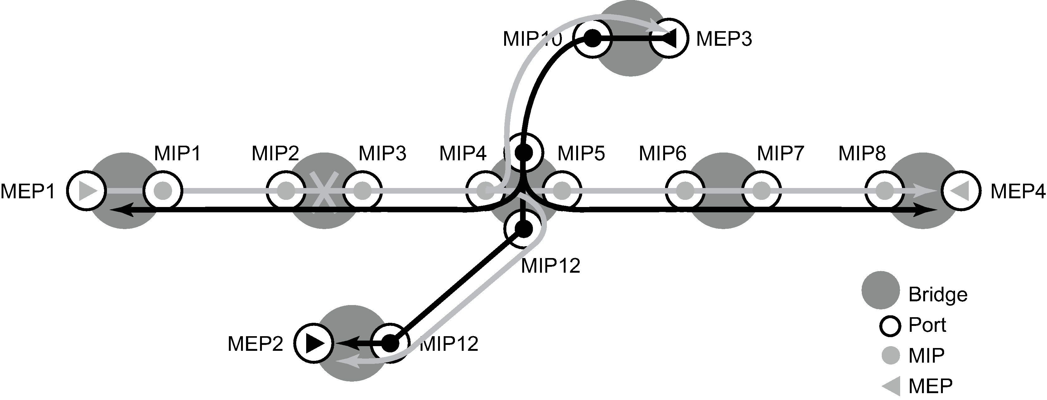
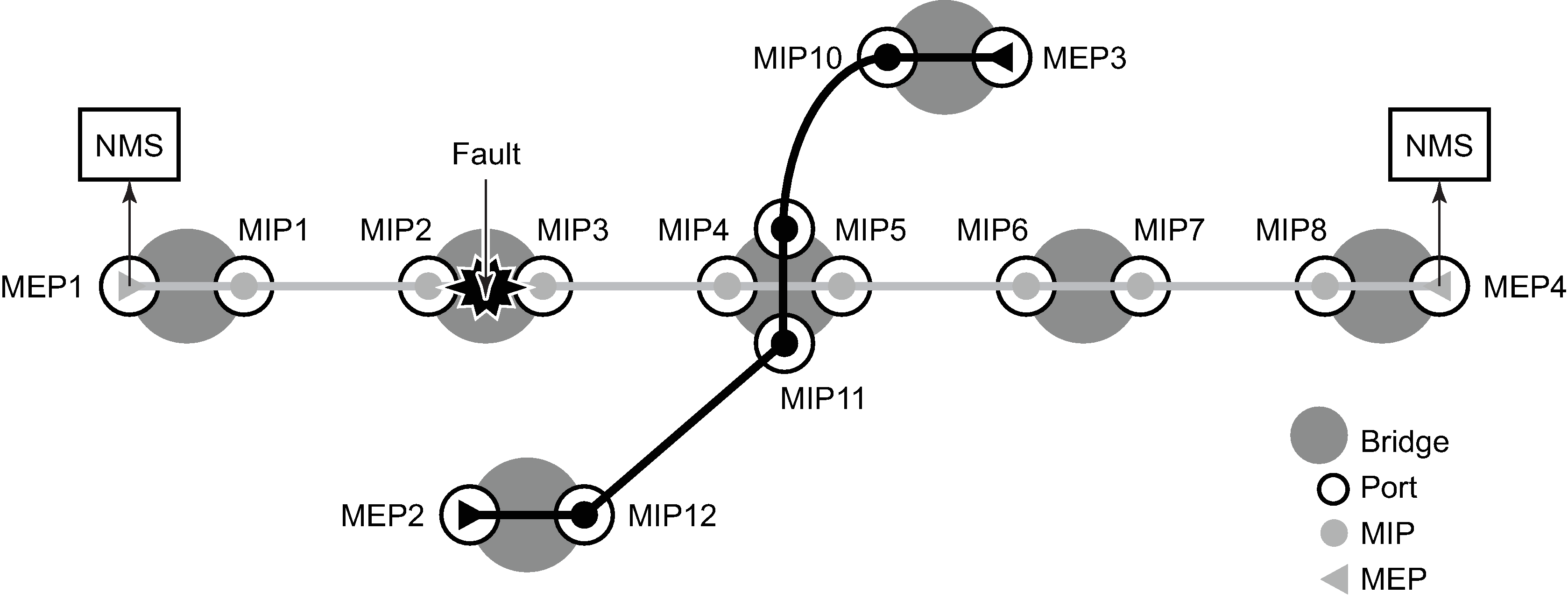
A Continuity Check Message (CCM) is a multicast frame that is generated by a MEP and multicast to all other MEPs in the same MA. The CCM does not require a reply message. To identify faults, the receiving MEP maintains an internal list of remote MEPs it should be receiving CCM messages from.
This list is based off of the remote-mepid configuration within the association the MEP is created in. When the local MEP does not receive a CCM from one of the configured remote MEPs within a pre-configured period, the local MEP raises an alarm.


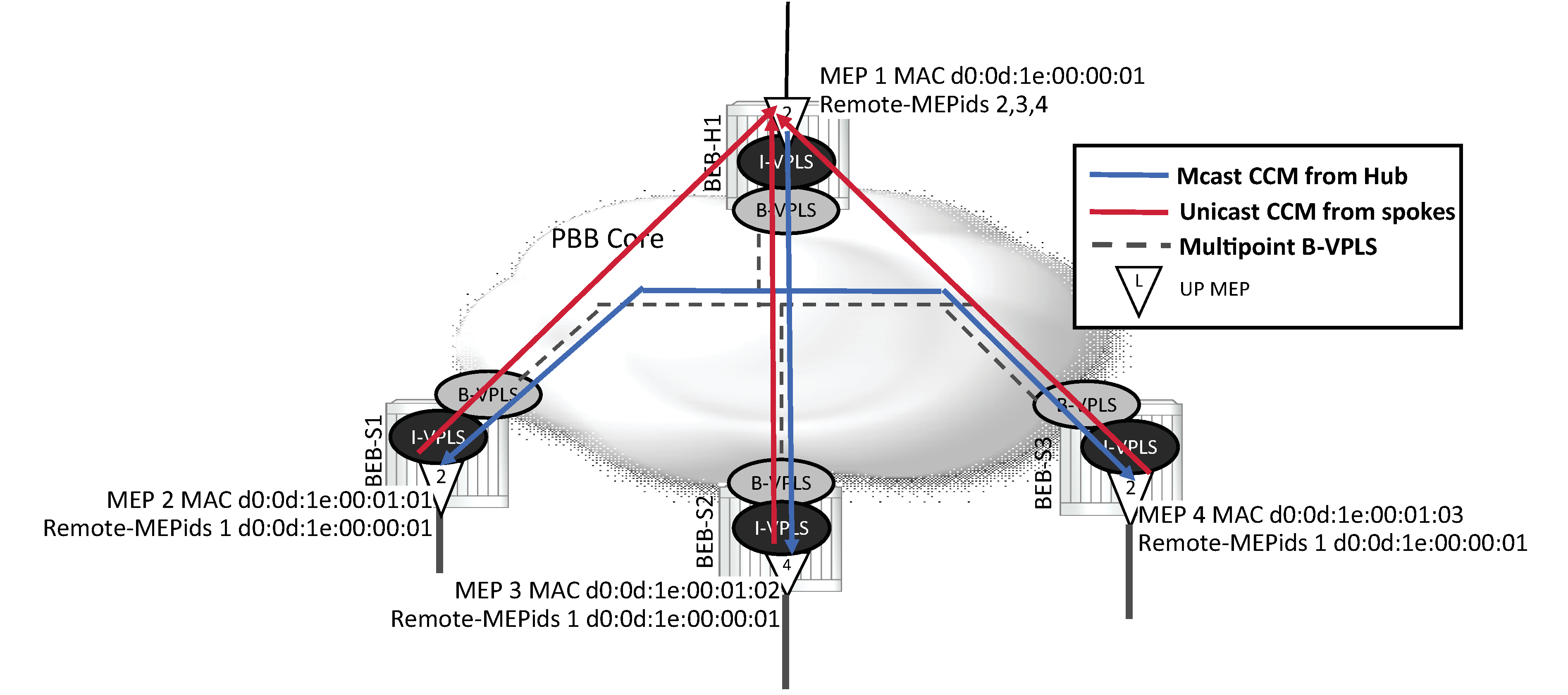
An MEP may be configured to generate ETH-CC packet using a unicast destination Layer 2 MAC address. This may help reduce the overhead in some operational models where Down MEPs per peer are not available. For example, mapping an I-VPLS to a PBB core where a hub is responsible for multiple spokes is one of the applicable models. When ETH-CFM packets are generated from an I-context toward a remote I-context, the packets traverse the B-VPLS context. Because many B-contexts are multipoint, any broadcast, unknown or multicast packet is flooded to all appropriate nodes in the B-context. When ETH-CC multicast packets are generated, all the I-VPLS contexts in the association must be configured with all the appropriate remote MEPids. If direct spoke to spoke connectivity is not part of the validation requirement, the operational complexity can be reduced by configuring unicast DA addressing on the ‟spokes” and continuing to use multicast CCM from the ‟hub”. When the unicast MAC is learned in the forwarding database, traffic is scoped to a single node.

Defect condition, reception, and processing remains unchanged for both hub and spokes. When an ETH-CC defect condition is raised on the hub or spoke, the appropriate defect condition is set and distributed throughout the association from the multicasting MEP. For example, should a spoke raise a defect condition or timeout, the hub sets the RDI bit in the multicast ETH-CC packet which is received on all spokes. Any local hub MEP defect condition continues to be propagated in the multicast ETH-CC packet. Defect conditions are cleared as per normal behavior.
The forwarding plane must be considered before deploying this type of ETH-CC model. A unicast packet is handled as unknown when the destination MAC does not exist in local forwarding table. If a unicast ETH-CC packet is flooded in a multipoint context, it reaches all the appropriate I-contexts. This causes the spoke MEPs to raise the ‟DefErrorCCM” condition because an ETH-CC packet was received from a MEP that has not been configured as part of the receiving MEPs database.
The remote unicast MAC address must be configured and is not automatically learned. A MEP cannot send both unicast and multicast ETH-CC packets. Unicast ETH-CC is only applicable to a local association with a single configured remote peer. There is no validation of MAC addresses for ETH-CC packets. The configured unicast destination MAC address of the peer MEP only replaces the multicast class 1 destination MAC address with a unicast destination.
Unicast CCM is not supported on any MEPs that are configured with sub second CCM-intervals.
The following functions are supported:
Enable and disable CC for an MEP
Configure and delete the MEP entries in the CC MEP monitoring database manually. It is only required to provision remote MEPs. Local MEPs shall be automatically put into the database when they are created.
CCM transmit interval: 10ms, 100ms, 1s, 10s 60s, 600s. Default: 10s. Interval support is platform dependent. When configuring MEPs with sub-second CCM intervals, bandwidth consumption must be taken into consideration. Each CCM PDU is approximately 100 bytes (800 bits). Taken individually, this is a small value. However, the bandwidth consumption increases rapidly as multiple MEPs are configured with 10ms timers, 100 packets per second.
The following section describes some basic hierarchical considerations and the software requirements and configurations that need to be met when considering sub-second enabled MEPs.
Down MEPs only
Single peer only
Any MD Level
As long as lower MD level MEPs are not CCM or ETH-APS enabled
G.8031 Ethernet-Tunnels enables OpCode39 Linear APS
G.8032 Ethernet-Rings enables OpCode 40 Ring APS
As long as lower MD levels MEPs are not receiving ETH-CCM or ETH-APS PDUs, even if they not locally enabled or configured to do so
The reception of the lower MD level ETH-CCM and ETH-APS PDUs are processed by the sub second CCM enabled MEP, regardless of MD Level
All other ETH-CFM PDUs are handled by the MEP at the MD level matching the PDU that has arrived, assuming one has been configured
Service MEPs (excluding primary VLAN MEPs)
Ethernet SAPs configured on Port with any Ethernet Encapsulation (null, dot1q or QinQ)
Facility MEPs
Ethernet Port Based MEPs
Ethernet LAG Based MEPs
Ethernet QinQ Tunnel based MEPs (LAG+VLAN, PORT+VLAN)
Base Router IP Interfaces
Service MEPs and Facility MEPs can simultaneously execute sub second CCM enabled MEPs as these are considered different MEP families.
General processing rules for Service MEPs and Facility MEPs must be met regardless of the CCM interval. These are included here because of the impact misunderstanding could have on the CCM extraction.
All the above rules apply
MD level hierarchy must be ensured across different families
Facility MEPs are the first processing routine for ETH-CFM PDUs
VLAN encapsulation uniqueness must exist when processing the ETH-CFM PDU across the two families
Unique Example: An Ethernet Port Based Facility Down MEP configured on port 1/1/1 and Service Down MEP SAP 1/1/1:100 (dot1q encaps) are unique
Conflict Example: An Ethernet Port Based Facility Down MEP configured on port 1/1/1 and Service Down MEP SAP 1/1/1 (null encaps) are in conflict and cannot coexist. All ETH-CFM PDUs arrive untagged and the Facility MEP takes precedence.
G.8031 (Ethernet-Tunnels) support both sub second and 1 second CCM intervals and optionally no CCM. When the MEP is created on a G.8031 Ethernet-Tunnel no other MEP that is any way connected to the G.8031 Ethernet-Tunnel can execute sub second CCM intervals. Facility MEPs are not supported in conjunction with G.8031 (Ethernet-Tunnel MEPs)
G.8032 (Ethernet-Ring) support both sub second and 1 second CCM intervals and optionally no CCM. Facility MEPs are supported in combination with G.8032 MEPs. However, facility MEPs and G.8032 MEPs cannot both execute sub second CCM where the infrastructure is shared. If the operator configures this combination the last updated sub second MEP overwrites the previous sub second MEP and interrupt the previous configured MEP causing a defRemoteCCM condition.
The size of the CCM PDU may be increased by configuring the optional Data TLV. This is accomplished by configuring the ccm-padding-size command under the specific MEP. The configured value represents the total length of the Data TLV that is included with the other CCM PDU informational elements. The no form of this command removes the optional Data TLV from the CCM PDU. The operator must consider a CCM PDU is 83 byte size in length (75 base elements plus 8 bytes for port status and interface status). If the size of the optional TLV combined with the size of the CCM PDU exceeds 1500 bytes the packet is dropped if the MTU is 1518/1522.
CCM declares a defect when:
it stops hearing from one of the remote MEPs for 3.5 times CC interval
it hears from a MEP with a LOWER MD level
it hears from a MEP that is not part of the local MEPs MA
it hears from a MEP that is in the same MA but not in the configured MEP list
it hears from a MEP in the same MA with the same MEP ID as the receiving MEP
the CC interval of the remote MEP does not match the local configured CC interval
the remote MEP is declaring a fault
An alarm is raised and a trap is sent if the defect is greater than or equal to the configured low-priority-defect value.
Remote Defect Indication (RDI) is supported but by default is not recognized as a defect condition because the low-priority-defect setting default does not include RDI.
SenderID TLV may optionally be configured to carry the ChassisID. When configured, this information is included in CCM messages.
Only the ChassisID portion of the TLV is included.
The Management Domain and Management Address fields are not supported on transmission.
SenderID TLV is not supported with sub second CCM enabled MEPs.
Supported for both service (id-permission) and facility MEPs (facility-id-permission).
Alarm notification alarm and reset times are configurable under the MEP. By default, the alarm notification times are set to zero, which means the behavior is immediate logging and resetting. When the value is zero and a previous higher level alarm is reset, if a lower level alarm exists, and is above the low-priority defect, a log event is created. However, when either of the alarm notification timers are non-zero and a lower priority alarm exists, it is not logged.
Alarm (fng-alarm-time) delays the generation of the log event by the value configured. The alarm must be present for this amount of time before the log event is created. This is for only log event purposes.
Reset (fng-reset-time) is the amount of time the alarm must be absent before it is cleared.
The optional ccm-tlv-ignore command ignores the reception of interface-status and port-status TLVs in the ETH-CCM PDU on Facility MEPs (port, LAG, QinQ, tunnel and router). No processing is performed on the ignored ETH-CCM TLVs values.
Any TLV that is ignored is reported as absent for that remote peer and the values in the TLV do not have an impact on the ETH-CFM state machine. This the same behavior as if the remote MEP never included the ignored TLVs in the ETH-CCM PDU. If the TLV is not properly formed, the CCM PDU fails the packet parsing process, which causes it to be discarded and a defect condition is raised.
There are various display commands that are available to show the status of the MEP and the list of remote peers.