4. Virtual Private LAN Service
This chapter provides information about Virtual Private LAN Service (VPLS), process overview, and implementation notes.
4.1. VPLS Service Overview
Virtual Private LAN Service (VPLS) is a class of virtual private network service that allows the connection of multiple sites in a single bridged domain over a provider-managed IP/MPLS network. The customer sites in a VPLS instance appear to be on the same LAN, regardless of their location. VPLS uses an Ethernet interface on the customer-facing (access) side which simplifies the LAN/WAN boundary and allows for rapid and flexible service provisioning. The 7210 SAS supports provisioning of access or uplink spokes to connect to the provider edge IP/MPLS routers.
VPLS provides a balance between point-to-point Frame Relay service and outsourced routed services (VPRN). VPLS enables each customer to maintain control of their own routing strategies. All customer routers in the VPLS service are part of the same subnet (LAN) which simplifies the IP addressing plan, especially when compared to a mesh constructed from many separate point-to-point connections. The VPLS service management is simplified since the service is not aware of nor participates in the IP addressing and routing.
A VPLS service provides connectivity between two or more SAPs on one (which is considered a local service) or more (which is considered a distributed service) service routers. The connection appears to be a bridged domain to the customer sites so protocols, including routing protocols, can traverse the VPLS service.
Other VPLS advantages include:
- VPLS is a transparent, protocol-independent service.
- There is no Layer 2 protocol conversion between LAN and WAN technologies.
- There is no need to design, manage, configure, and maintain separate WAN access equipment, therefore, eliminating the need to train personnel on WAN technologies such as Frame Relay.
4.1.1. VPLS Packet Walkthrough
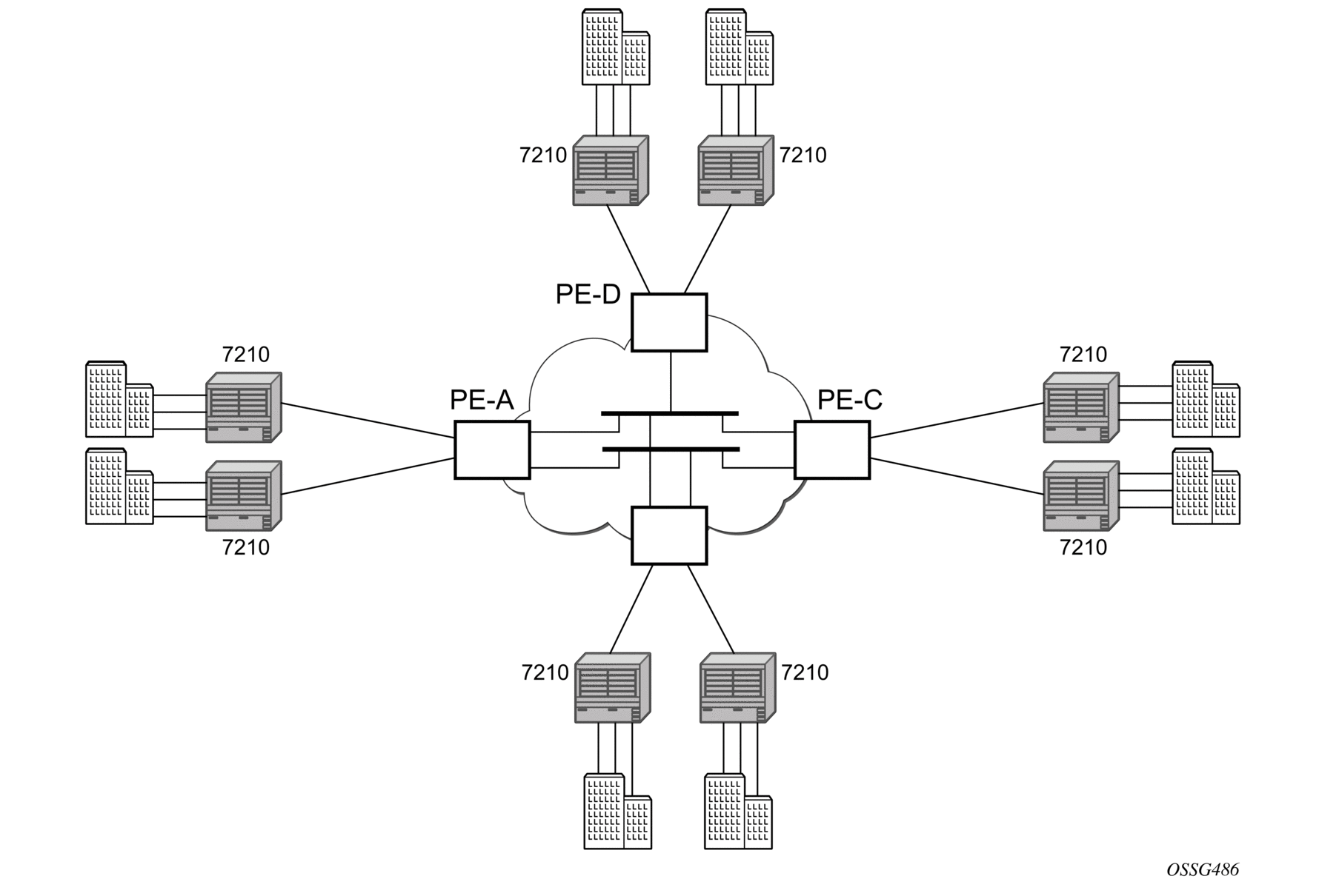
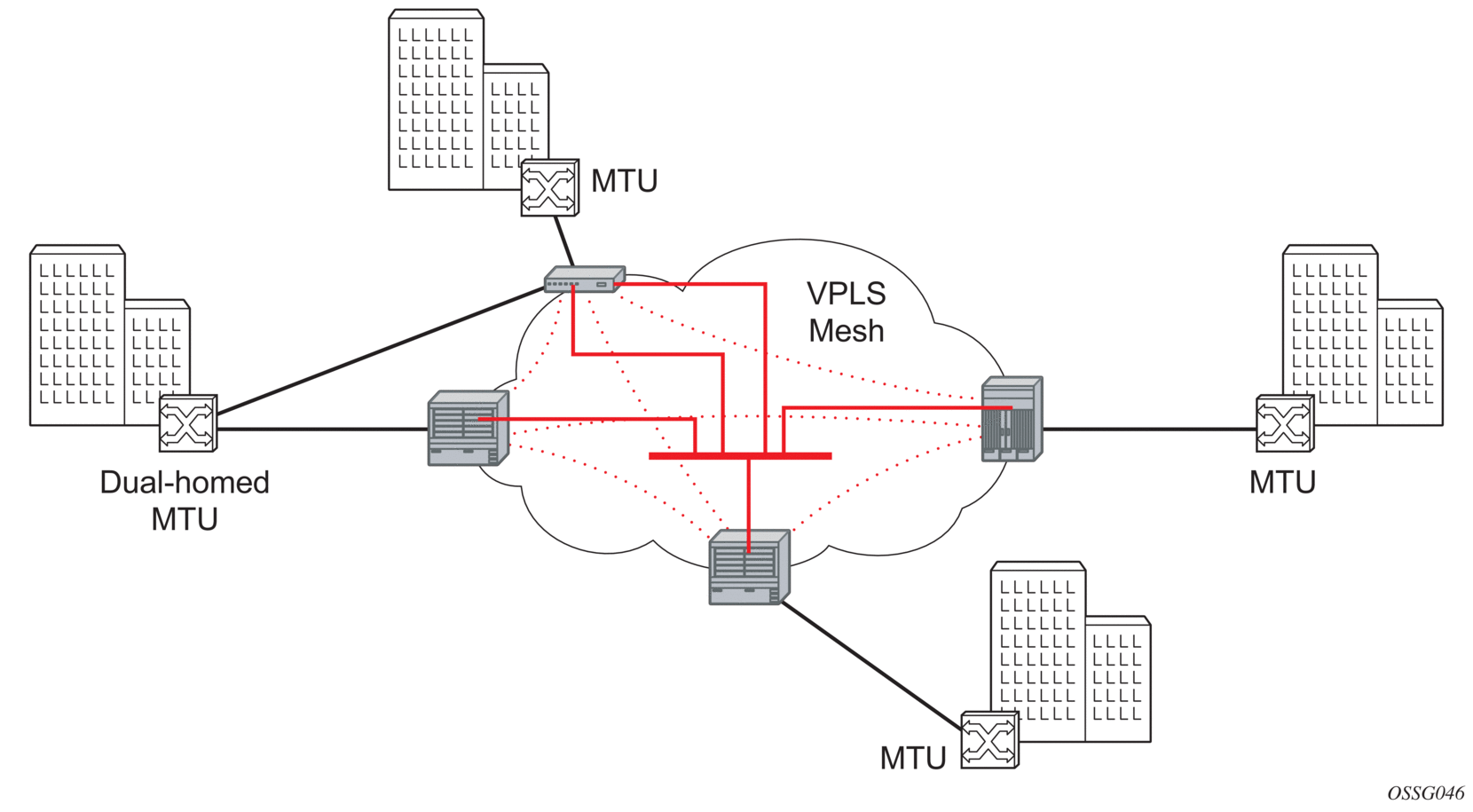
This section provides an example of VPLS processing of a customer packet sent across the network from site-A, which is connected to PE-Router-A through a 7210 SAS to site-C, which is connected through 7210 SAS to PE-Router-C (shown in Figure 34) in an H-VPLS configuration. This section does not describe the processing on the PE routers, but only on 7210 SAS routers.
Figure 34: VPLS Service Architecture
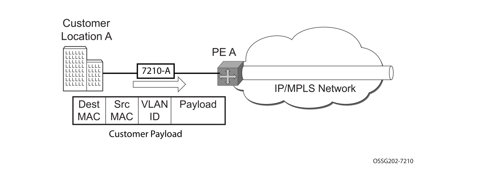
- 7210-A (Figure 35)
- Service packets arriving at are associated with a VPLS service instance based on the combination of the physical port and the IEEE 802.1Q tag (VLAN-ID) in the packet.
Figure 35: Access Port Ingress Packet Format and Lookup
- 7210-A learns the source MAC address in the packet and creates an entry in the FIB table that associates the MAC address to the service access point (SAP) on which it was received.
- The destination MAC address in the packet is looked up in the FIB table for the VPLS instance. There are two possibilities: either the destination MAC address has already been learned (known MAC address) or the destination MAC address is not yet learned (unknown MAC address). For a Known MAC Address (Figure 36).
- If the destination MAC address has already been learned by 7210, an existing entry in the FIB table identifies the far-end PE-Router and the service VC-label (inner label) to be used before sending the packet to PE-Router-A.
- The 7210 SAS chooses a transport LSP to send the customer packets to PE-Router-A. The customer packet is sent on this LSP when the IEEE 802.1Q tag is stripped and the service VC-label (inner label) and the transport label (outer label) are added to the packet. For an Unknown MAC Address (Figure 37).
- If the destination MAC address has not been learned, 7210 will flood the packet to spoke-SDPs that are participating in the service.
Figure 36: Network Port Egress Packet Format and Flooding Customer Location A
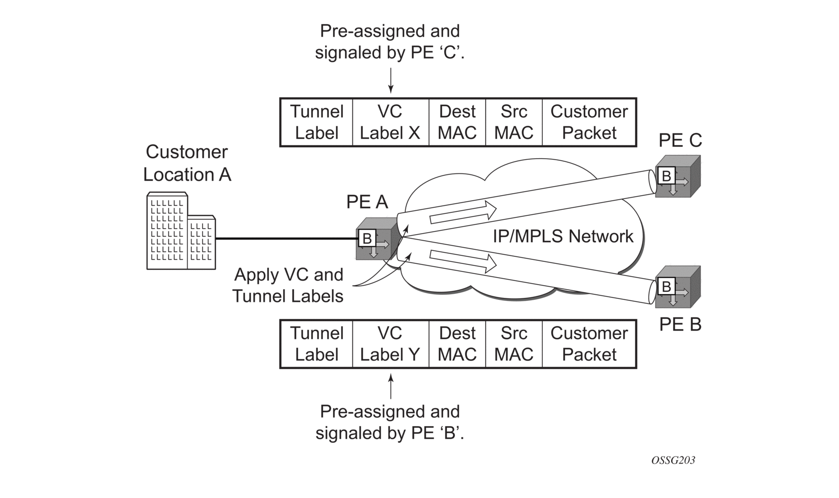
Figure 37: Network Port Egress Packet Format and Flooding
- Core Router Switching
- All the core routers ('P' routers in IETF nomenclature) between PE-Router-A and PE-Router-B and PE-Router-C are Label Switch Routers (LSRs) that switch the packet based on the transport (outer) label of the packet until the packet arrives at far-end PE-Router. All core routers are unaware that this traffic is associated with a VPLS service.
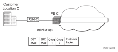
- 7210-C (Figure 35)
- 7210-C associates the packet with the VPLS instance based on the VC label in the received packet after the stripping of the tunnel label.
- 7210-C learns the source MAC address in the packet and creates an entry in the FIB table that associates the MAC address to the spoke-SDP on which the packet was received.
- The destination MAC address in the packet is looked up in the FIB table for the VPLS instance. Again, there are two possibilities: either the destination MAC address has already been learned (known MAC address) or the destination MAC address has not been learned on the access side of 7210-C (unknown MAC address).
- If the destination MAC address has been learned by an existing entry in the FIB table identifies the local access port and the IEEE 802.1Q tag to be added before sending the packet to customer Location-C. The egress Q tag may be different from the ingress Q tag.
- If the destination MAC address has not been learned, 7210 will flood the packet to all the access SAPs that are participating in the service.
4.2. VPLS Features
This section describes VPLS features.
4.2.1. VPLS Enhancements
The Nokia VPLS implementation includes several enhancements beyond basic VPN connectivity. The following VPLS features can be configured individually for each VPLS service instance:
- Extensive MAC and IP filter support (up to Layer 4). Filters can be applied on a per SAP basis.
- Forwarding Information Base (FIB) management features including:
- Configurable FIB size limit
- FIB size alarms
- MAC learning disable
- Discard unknown
- Separate aging timers for locally and remotely learned MAC addresses.
- Ingress rate limiting for broadcast, multicast, and destination unknown flooding on a per SAP basis.
- Implementation of Spanning Tree Protocol (STP) parameters on a per VPLS, per SAP and per spoke-SDP basis.
- Optional SAP and/or spoke-SDP redundancy to protect against node failure.
- IGMP snooping on a per-SAP and SDP basis.
4.2.2. VPLS over MPLS
The VPLS architecture proposed in draft-ietf-ppvpn-vpls-ldp-0x.txt specifies the use of provider equipment (PE) that is capable of learning, bridging, and replication on a per-VPLS basis. The PE routers that participate in the service are connected using MPLS Label Switched Path (LSP) tunnels in a full-mesh composed of mesh SDPs or based on an LSP hierarchy (Hierarchical VPLS (H-VPLS)) composed of mesh SDPs and spoke SDPs. The 7210 SAS M supports only H-VPLS.
Multiple VPLS services can be offered over the same set of LSP tunnels. Signaling specified in RFC 4905 is used to negotiate a set of ingress and egress VC labels on a per-service basis. The VC labels are used by the PE routers for de-multiplexing traffic arriving from different VPLS services over the same set of LSP tunnels.
H-VPLS is provided over MPLS by:
- connecting the 7210 SAS-R6 and 7210 SAS-R12 to bridging-capable provider edge (PE) routers through a spoke-SDP. The PE routers are connected using a full mesh of LSPs.
- negotiating per-service VC labels using draft-Martini encapsulation
- replicating unknown and broadcast traffic in a service domain
- enabling MAC learning over tunnel and access ports (see VPLS MAC Learning and Packet Forwarding).
- using a separate forwarding information base (FIB) per VPLS service
4.2.3. VPLS MAC Learning and Packet Forwarding
The 7210 SAS edge devices perform the packet replication required for broadcast and multicast traffic across the bridged domain. MAC address learning is performed by the 7210 SAS device to reduce the amount of unknown destination MAC address flooding.
Each 7210 SAS maintains a Forwarding Information Base (FIB) for each VPLS service instance and learned MAC addresses are populated in the FIB table of the service. All traffic is switched based on MAC addresses and forwarded between all participating nodes using the LSP tunnels. Unknown destination packets (for example, the destination MAC address has not been learned) are forwarded on all LSPs to all participating nodes for that service until the target station responds and the MAC address is learned by the 7210 SAS associated with that service.
4.2.4. Configuration Notes for VPLS Forwarding
The 7210 SAS-R6 and 7210 SAS-R12 devices, uses the packet header fields that computes the hash for unicast traffic to be sent out of a SAP configured over a LAG and forwards it over the member ports of the LAG. For unknown unicast, broadcast and multicast traffic, it does not compute a hash and forwards all traffic out of the primary port of the LAG. For more information, refer to the 7210 SAS-M, T, R6, R12, Mxp, Sx, S Interface Configuration Guide.
4.2.5. IGMP Snooping in VPLS Service
| Note: This section provides information about IGMP snooping support in a VPLS service. It does not apply to routed VPLS (RVPLS) services. IGMP snooping can also be enabled for routed VPLS services. See Routed VPLS and IGMPv3 Snooping for details. |
In Layer 2 switches, multicast traffic is treated like an unknown MAC address or broadcast frame, which causes the incoming frame to be flooded out (broadcast) on every port within a VLAN. Although this is acceptable behavior for unknowns and broadcast frames, this flooded multicast traffic may result in wasted bandwidth on network segments and end stations, as IP multicast hosts can join and be interested in only specific multicast groups.
IGMP snooping entails using information in Layer 3 protocol headers of multicast control messages to determine the processing at Layer 2. By doing so, an IGMP snooping switch provides the benefit of conserving bandwidth on those segments of the network in which no node has expressed interest in receiving packets addressed to the group address.
IGMP snooping can be enabled in the context of VPLS services. The IGMP snooping feature allows for optimization of the multicast data flow to only those SAPs or SDPs that are members of the group. The system builds a database of group members per service by listening to IGMP queries and reports from each SAP or SDP, as follows:
- When the switch receives an IGMP report from a host for a particular multicast group, the switch adds the host port number to the forwarding table entry.
- When it receives an IGMP leave message from a host, it removes the host port from the table entry, if no other group members are present. It also deletes entries if it does not receive periodic IGMP membership reports from the multicast clients.
The following are IGMP snooping features:
- IGMP v1, v2, and v3 are supported (RFC 1112, Host Extensions for IP Multicasting, and RFC 2236, Internet Group Management Protocol, Version 2).
- IGMP snooping can be enabled and disabled on individual VPLS service instances.
- IGMP snooping can be configured on individual SAPs that are part of a VPLS service. When IGMP snooping is enabled on a VPLS service, all its contained SAPs and SDPs automatically have snooping enabled.
- Fast leave terminates the multicast session immediately, rather than using the standard group-specific query to check if other group members are present on the network.
- SAPs and SDPs can be statically configured as multicast router ports. This allows the operator to control the set of ports to which IGMP membership reports are forwarded.
- Static multicast group membership on a per SAP and as per SDP basis can be configured.
- The maximum number of multicast groups (static and dynamic) that a SAP or SDP can join can be configured. An event is generated when the limit is reached.
- The maximum number of multicast groups (static and dynamic) that a VPLS instance simultaneously supports can be configured.
- Proxy summarization of IGMP messages reduces the number of IGMP messages processed by upstream devices in the network.
- IGMP filtering allows a subscriber to a service or the provider to block, receive, or transmit permission (or both) to individual hosts or a range of hosts. The following types of filters can be defined:
- Filter group membership that report from a particular host or range of hosts. This filtering is performed by importing an appropriately-defined routing policy into the SAP or SDP.
- Filters that prevent a host from transmitting multicast streams into the network. The operator can define a data-plane filter (ACL) that drops all multicast traffic, and apply this filter to a SAP or SDP.
4.2.5.1. Configuration Guidelines for IGMP Snooping in VPLS Service
The following IGMP snooping considerations apply:
- Layer 2 multicast is supported in VPLS services.
- IGMP snooping is not supported for VCs (either VC-Ether or VC-VLAN) with control-word enabled.
- IGMP snooping fast leave processing can be enabled only on SAPs and SDPs. IGMP snooping proxy summarization is enabled by default on SAPS and SDPs and cannot be disabled. Proxy summarization and fast leave processing are supported only on SDPs whose VC are configured to use vc-type ether and do not have control-word enabled.
- IGMP filtering using policies is available on SAPs and SDPs. It is supported only on SDPs whose VC are configured to use vc-type ether and do not have control-word enabled.
- Dynamic learning is only supported on SDPs whose VC are configured to use vc-type ether and do not have control-word enabled.
- SDPs that are configured to use VC of type vc-vlan that need to be router ports must be configured statically. Multicast group memberships for such SDPs must be configured statically. Dynamic learning is not available for these SDPs.
- IGMP snooping is not supported for control word-enabled SDPs.
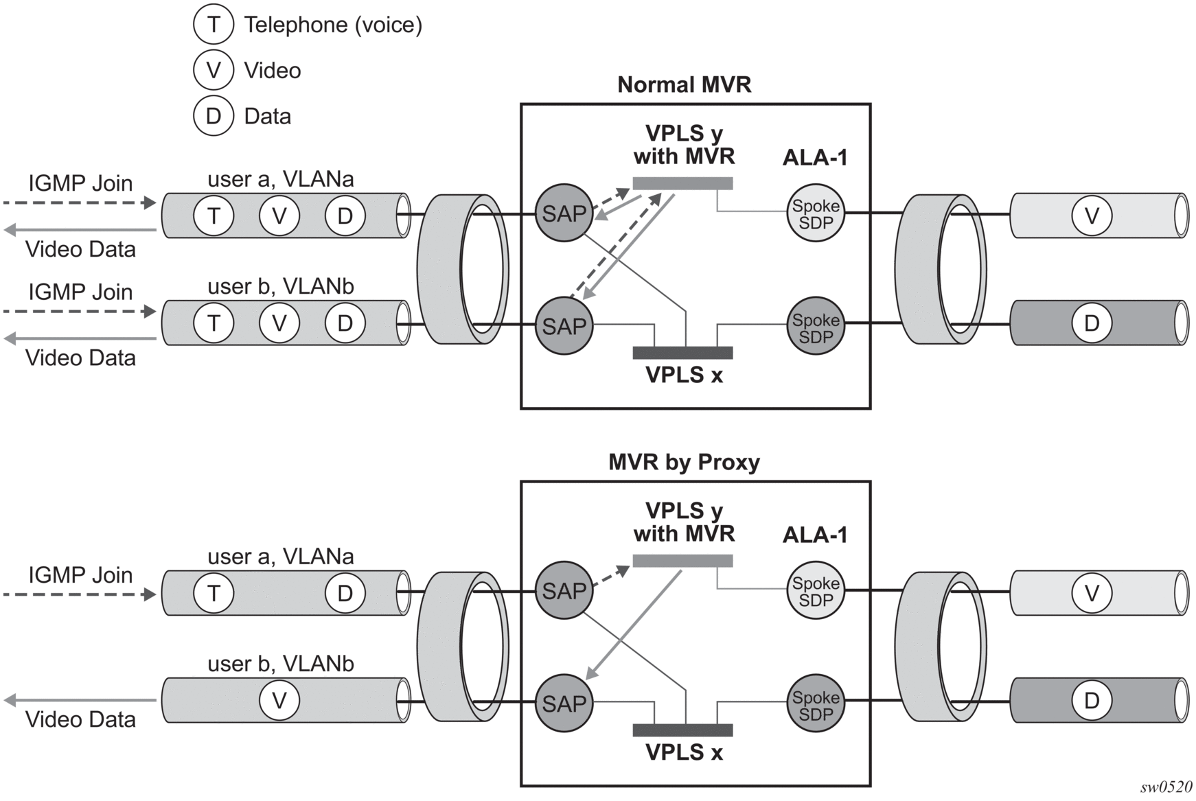
4.2.6. Multicast VLAN Registration (MVR) Support in VPLS Service
Multicast VPLS Registration (MVR) is a bandwidth optimization method for multicast in a broadband services network. MVR allows a subscriber on a port to subscribe and unsubscribe to a multicast stream on one or more network-wide multicast VPLS instances.
MVR assumes that subscribers join and leave multicast streams by sending IGMP join and leave messages. The IGMP leave and join message are sent inside the VPLS to which the subscriber port is assigned. The multicast VPLS is shared in the network while the subscribers remain in separate VPLS services. Using MVR, users on different VPLS cannot exchange any information between them, but still multicast services are provided.
On the MVR VPLS, IGMP snooping must be enabled. On the user VPLS, IGMP snooping and MVR work independently. If IGMP snooping and MVR are both enabled, MVR reacts only to join and leave messages from multicast groups configured under MVR. Join and leave messages from all other multicast groups are managed by IGMP snooping in the local VPLS. This way, potentially several MVR VPLS instances could be configured, each with its own set of multicast channels.
MVR by proxy — In some situations, the multicast traffic should not be copied from the MVR VPLS to the SAP on which the IGMP message was received (standard MVR behavior) but to another SAP. This is called MVR by proxy and is shown in Figure 38.
Figure 38: MVR and MVR by Proxy
4.2.6.1. Configuration Guidelines for MVR in VPLS Service
In a MVR configuration, the svc-sap-type of the VPLS service that is the source (also known as MVR VPLS service) and the svc-sap-type of the VPLS service that is the sink (also known as user VPLS service) should match.
4.2.7. Layer 2 Forwarding Table Management
The following sections describe VPLS features related to management of the Forwarding Information Base (FIB).
4.2.7.1. FIB Size
The following MAC table management features are required for each instance of a SAP or spoke-SDP within a particular VPLS service instance:
- MAC FIB size limits — Allows users to specify the maximum number of MAC FIB entries that are learned locally for a SAP or remotely for a spoke-SDP. If the configured limit is reached, then no new addresses will be learned from the SAP or spoke-SDP until at least one FIB entry is aged out or cleared.
- When the limit is reached on a SAP, packets with unknown source MAC addresses are still forwarded (this default behavior can be changed by configuration). By default, if the destination MAC address is known, it is forwarded based on the FIB, and if the destination MAC address is unknown, it will be flooded. Alternatively, if discard unknown is enabled at the VPLS service level, unknown destination MAC addresses are discarded.
- The log event SAP MAC limit reached is generated when the limit is reached. When the condition is cleared, the log event SAP MAC Limit Reached Condition Cleared is generated.
- Disable learning at the VPLS service level allows users to disable the dynamic learning function on the service. Disable Learning is supported at the SAP and spoke-SDP level as well.
- Disable aging allows users to turn off aging for learned MAC addresses. It is supported at the VPLS service level, SAP level and spoke-SDP level
4.2.7.2. FIB Size Alarms
The size of the VPLS FIB can be configured with a low watermark and a high watermark, expressed as a percentage of the total FIB size limit. If the actual FIB size grows above the configured high watermark percentage, an alarm is generated. If the FIB size falls below the configured low watermark percentage, the alarm is cleared by the system.
4.2.7.3. Local and Remote Aging Timers
Like a Layer 2 switch, learned MACs within a VPLS instance can be aged out if no packets are sourced from the MAC address for a specified period of time (the aging time). In each VPLS service instance, there are independent aging timers for locally learned MAC and remotely learned MAC entries in the forwarding database (FIB). A local MAC address is a MAC address associated with a SAP because it ingressed on a SAP. A remote MAC address is a MAC address received by an SDP from another router for the VPLS instance. The local-age timer for the VPLS instance specifies the aging time for locally learned MAC addresses, and the remote-age timer specifies the aging time for remotely learned MAC addresses.
In general, the remote-age timer is set to a longer period than the local-age timer to reduce the amount of flooding required for destination unknown MAC addresses. The aging mechanism is considered a low priority process. In most situations, the aging out of MAC addresses can happen in within tens of seconds beyond the age time. To minimize overhead, local MAC addresses on a LAG port and remote MAC addresses, in some circumstances, can take up to two times their respective age timer to be aged out.
4.2.7.4. Disable MAC Aging
The MAC aging timers can be disabled which will prevent any learned MAC entries from being aged out of the FIB. When aging is disabled, it is still possible to manually delete or flush learned MAC entries. Aging can be disabled for learned MAC addresses on a SAP or a spoke-SDP of a VPLS service instance.
4.2.7.5. Disable MAC Learning
When MAC learning is disabled for a service, new source MAC addresses are not entered in the VPLS FIB. MAC learning can be disabled for individual SAPs or spoke-SDPs.
4.2.7.6. Unknown MAC Discard
Unknown MAC discard is a feature which discards all packets ingressing the service where the destination MAC address is not in the FIB. The normal behavior is to flood these packets to all end points in the service.
Unknown MAC discard can be used with the disable MAC learning and disable MAC aging options to create a fixed set of MAC addresses allowed to ingress and traverse the service.
4.2.7.7. VPLS and Rate Limiting
Traffic that is flooded throughout the VPLS can be rate limited on SAP ingress through the use of service ingress QoS policies. In a service ingress QoS policy, individual meters can be defined per forwarding class to provide rate-limiting/policing of broadcast traffic, MAC multicast traffic and unknown destination MAC traffic.
4.2.7.8. MAC Move
The MAC move feature is useful to protect against undetected loops in a VPLS topology as well as the presence of duplicate MACs in a VPLS service.
If two clients in the VPLS have the same MAC address, the VPLS will experience a high relearn rate for the MAC. When MAC move is enabled, the 7210 SAS-R6 and 7210 SAS-R12 will shut down the SAP or spoke-SDP and create an alarm event when the threshold is exceeded.
MAC move allows sequential order port blocking. By configuration, some VPLS ports can be configured as “non-blockable” which allows simple level of control which ports are being blocked during loop occurrence.
4.2.7.8.1. Split Horizon SAP Groups and Split Horizon Spoke-SDP Groups
Within the context of VPLS services, a loop-free topology inside a fully meshed VPLS core is achieved by applying a split-horizon forwarding concept.The packets received from a mesh SDP are never forwarded to other mesh SDPs within the same service. The advantage of this approach is that no protocol is required to detect loops within the VPLS core network.
In applications such as DSL aggregation, it is useful to extend this split-horizon concept also to groups of SAPs and/or spoke-SDPs. This extension is referred to as a split horizon SAP group. Traffic arriving on a SAP or a spoke-SDP within a split horizon group will not be forwarded to other SAPs and spoke SDPs configured in the same split horizon group, but will be forwarded to other SAPs/spoke-SDPs, which are not part of the split horizon group.
4.2.7.8.2. Configuration Guidelines for use of Split Horizon Group in a VPLS Service
On all 7210 SAS platforms, except for 7210 SAS-R6 and 7210 SAS-R12 IMM-b, mesh SDPs cannot be configured in a service which uses split horizon group. Conversely, if a service has a mesh-sdp configured, split horizon group cannot be used in the same service. On 7210 SAS-R6 and 7210 SAS-R12 IMM-b, SHG can be configured along with spoke-SDP and mesh-SDP.
4.2.8. VPLS and Spanning Tree Protocol
The Nokia VPLS service provides a bridged or switched Ethernet Layer 2 network. Equipment connected to SAPs forward Ethernet packets into the VPLS service. The participating in the service learns where the customer MAC addresses reside, on ingress SAPs.
Unknown destinations, broadcasts, and multicasts are flooded to all other SAPs in the service. If SAPs are connected together, either through misconfiguration or for redundancy purposes, loops can form and flooded packets can keep flowing through the network. The Nokia implementation of the Spanning Tree Protocol (STP) is designed to remove these loops from the VPLS topology. This is done by putting one or several SAPs in the discarding state.
The Nokia implementation of the Spanning Tree Protocol (STP) incorporates some modifications to make the operational characteristics of VPLS more effective.
The STP instance parameters allow the balancing between resiliency and speed of convergence extremes. Modifying particular parameters can affect the behavior. For information about command usage, descriptions, and CLI syntax, refer to Configuring a VPLS Service with CLI.
4.2.8.1. Spanning Tree Operating Modes
Per VPLS instance, a preferred STP variant can be configured. The STP variants supported are:
- rstp — Rapid Spanning Tree Protocol (RSTP) compliant with IEEE 802.1D-2004 - default mode
- dot1w — Compliant with IEEE 802.1w
- comp-dot1w — Operation as in RSTP but backwards compatible with IEEE 802.1w (this mode allows interoperability with some MTU types)
- mstp — Compliant with the Multiple Spanning Tree Protocol specified in IEEE 802.1Q-REV/D5.0-09/2005. This mode of operation is only supported in an mVPLS.
While the 7210 SAS initially uses the mode configured for the VPLS, it will dynamically fall back (on a per-SAP basis) to STP (IEEE 802.1D-1998) based on the detection of a BPDU of a different format. A trap or log entry is generated for every change in spanning tree variant.
Some older 802.1W compliant RSTP implementations may have problems with some of the features added in the 802.1D-2004 standard. Interworking with these older systems is improved with the comp-dot1w mode. The differences between the RSTP mode and the comp-dot1w mode are:
- The RSTP mode implements the improved convergence over shared media feature, for example, RSTP will transition from discarding to forwarding in 4 seconds when operating over shared media. The comp-dot1w mode does not implement this 802.1D-2004 improvement and transitions conform to 802.1w in 30 seconds (both modes implement fast convergence over point-to-point links).
- In the RSTP mode, the transmitted BPDUs contain the port's designated priority vector (DPV) (conforms to 802.1D-2004). Older implementations may be confused by the DPV in a BPDU and may fail to recognize an agreement BPDU correctly. This would result in a slow transition to a forwarding state (30 seconds). For this reason, in the comp-dot1w mode, these BPDUs contain the port's port priority vector (conforms to 802.1w).
The 7210 SAS supports BDPU encapsulation formats, and can dynamically switch between the following supported formats (on a per-SAP basis):
- IEEE 802.1D STP
- Cisco PVST
4.2.8.2. Multiple Spanning Tree
The Multiple Spanning Tree Protocol (MSTP) extends the concept of the IEEE 802.1w Rapid Spanning Tree Protocol (RSTP) by allowing grouping and associating VLANs to Multiple Spanning Tree Instances (MSTI). Each MSTI can have its own topology, which provides architecture enabling load balancing by providing multiple forwarding paths. At the same time, the number of STP instances running in the network is significantly reduced as compared to Per VLAN STP (PVST) mode of operation. Network fault tolerance is also improved because a failure in one instance (forwarding path) does not affect other instances.
The 7210 SAS implementation of Management VPLS (mVPLS) is used to group different VPLS instances under single RSTP instance. Introducing MSTP into the mVPLS allows the following:
- Interoperation with traditional Layer 2 switches in access network.
- Provides an effective solution for dual homing of many business Layer 2 VPNs into a provider network.
4.2.8.2.1. Configuration notes for Spanning Tree Protocol, L2PT and BPDU translation
The 7210 SAS-R6 and 7210 SAS-R12 devices, reserves some entries in the L2 FIB table for use with xSTP, L2PT and BPDU translation. A fixed amount of such resources are available per node. The user has an option to allocate these resources to services, where they plan to use one of these protocols, at service creation time. This is achieved with the new CLI parameter "allow-l2pt-xstp-bpdu [enable | disable]". This is a mandatory parameter that the user must configure if they plan to enable one of these protocols in the service. The software fails any attempt to enable these protocols, if this parameter has not been configured for the service.
4.2.8.3. MSTP for QinQ SAPs
MSTP runs in a MVPLS context and can control SAPs from source VPLS instances. QinQ SAPs are supported. The outer tag is considered by MSTP as part of VLAN range control
4.2.8.4. Enhancements to the Spanning Tree Protocol
To interconnect 7210 SAS devices (PE devices) across the backbone, service tunnels (SDPs) are used. These service tunnels are shared among multiple VPLS instances. The Nokia implementation of the Spanning Tree Protocol (STP) incorporates some enhancements to make the operational characteristics of VPLS more effective. The implementation of STP on the router is modified to guarantee that service tunnels will not be blocked in any circumstance without imposing artificial restrictions on the placement of the root bridge within the network. The modifications introduced are fully compliant with the 802.1D-2004 STP specification.
When running MSTP, spoke-SDPs cannot be configured. Also, ensure that all bridges connected by mesh SDPs are in the same region. If not, the mesh will be prevented from becoming active (trap is generated).
To achieve this, all mesh SDPs are dynamically configured as either root ports or designated ports. The PE devices participating in each VPLS mesh determine (using the root path cost learned as part of the normal protocol exchange) which of the 7210 SAS devices is closest to the root of the network. This PE device is internally designated as the primary bridge for the VPLS mesh. As a result of this, all network ports on the primary bridges are assigned the designated port role and therefore remain in the forwarding state.
The second part of the solution ensures that the remaining PE devices participating in the STP instance see the SDP ports as a lower cost path to the root rather than a path that is external to the mesh. Internal to the PE nodes participating in the mesh, the SDPs are treated as zero cost paths toward the primary bridge. As a consequence, the path through the mesh are seen as lower cost than any alternative and the PE node will designate the network port as the root port. This ensures that network ports always remain in forwarding state.
A combination of the preceding features ensure that network ports are never blocked and maintain interoperability with bridges external to the mesh that are running STP instances.
4.2.8.4.1. L2PT Termination
L2PT is used to transparently transport protocol data units (PDUs) of Layer 2 protocols such as STP, CDP, DTP, VTP, PAGP, and UDLD. This allows running these protocols between customer CPEs without involving backbone infrastructure.
The 7210 SAS routers allow transparent tunneling of PDUs across the VPLS core. However, in some network designs, the VPLS PE is connected to CPEs through a legacy Layer 2 network, rather than having direct connections. In such environments termination of tunnels through such infrastructure is required.
L2PT tunnels protocol PDUs by overwriting MAC destination addresses at the ingress of the tunnel to a proprietary MAC address such as 01-00-0c-cd-cd-d0. At the egress of the tunnel, this MAC address is then overwritten back to MAC address of the respective Layer 2 protocol.
The 7210 SAS nodes support L2PT termination for STP BPDUs. More specifically:
- At ingress of every SAP which is configured as L2PT termination, all PDUs with a MAC destination address, 01-00-0c-cd-cd-d0 will be intercepted and their MAC destination address will be overwritten to MAC destination address used for the corresponding protocol. The type of protocol can be derived from LLC and SNAP encapsulation.
- In egress direction, PDUs of the corresponding protocol received on all VPLS ports will be intercepted and L2PT encapsulation will be performed for SAPs configured as L2PT termination points. Because of the implementation reasons, PDU interception and redirection to CPM can be performed only at ingress. Therefore, to comply with the preceding requirement, as soon as at least 1 port of a specific VPLS service is configured as L2PT termination port, redirection of PDUs to CPM will be set on all other ports (SAPs) of the VPLS service.
L2PT termination can be enabled only if STP is disabled in a context of the specific VPLS service.
4.2.8.4.2. BPDU Translation
VPLS networks are typically used to interconnect different customer sites using different access technologies such as Ethernet and bridged-encapsulated ATM PVCs. Typically, different Layer 2 devices can support different types of STP and even if they are from the same vendor. In some cases, it is necessary to provide BPDU translation to provide an interoperable e2e solution.
To address these network designs, BPDU format translation is supported on 7210 SAS devices. If enabled on a specific SAP, the system will intercept all BPDUs destined to that interface and perform required format translation such as STP-to-PVST or vice versa.
Similarly, BPDU interception and redirection to the CPM is performed only at ingress meaning that as soon as at least 1 port within a specific VPLS service has BPDU translation enabled, all BPDUs received on any of the VPLS ports will be redirected to the CPM.
BPDU translation involves all encapsulation actions that the data path would perform for a specific outgoing port (such as adding VLAN tags depending on the outer SAP and adding or removing all the required VLAN information in a BPDU payload.
This feature can be enabled on a SAP only if STP is disabled in the context of the specific VPLS service.
4.2.8.4.3. L2PT and BPDU Translation
L2PT termination for only STP (Spanning Tree Protocol) and PVST (Per VLAN Spanning Tree Protocol), Cisco Discovery Protocol (CDP), Digital Trunking Protocol (DTP), Port Aggregation Protocol (PAgP), Uni-directional Link Detection (UDLD), Virtual Trunk Protocol (VTP), STP (Spanning Tree Protocol) and PVST (per-VLAN Spanning Tree protocol) are supported on 7210 SAS devices.
These protocols automatically pass the other protocols tunneled by L2PT toward the CPM and all carry the same specific Cisco MAC.
The existing L2PT limitations apply.
- The protocols apply only to VPLS.
- The protocols are mutually exclusive with running STP on the same VPLS as soon as one SAP has L2PT/BPDU translation enabled.
- Forwarding occurs on the CPM and uses CPU processing cycles.
4.2.9. VPLS Redundancy
The VPLS standard (RFC 4762, Virtual Private LAN Services Using LDP Signaling) includes provisions for hierarchical VPLS, using point-to-point spoke SDPs. Two applications have been identified for spoke SDPs:
- To connect to Multi-Tenant Units (MTUs) to PEs in a metro area network;
- To interconnect the VPLS nodes of two networks.
In both applications the spoke SDPs serve to improve the scalability of VPLS. While node redundancy is implicit in non-hierarchical VPLS services (using a full mesh of SDPs between PEs), node redundancy for spoke SDPs needs to be provided separately. In VPLS services, only two spoke-SDPs are allowed in an endpoint.
Nokia routers have implemented special features for improving the resilience of hierarchical VPLS instances, in both MTU and inter-metro applications.
4.2.9.1. Spoke-SDP Redundancy for Metro Interconnection
When two or more meshed VPLS instances are interconnected by redundant spoke SDPs (as shown in Figure 39), a loop in the topology results. To remove such a loop from the topology, Spanning Tree Protocol (STP) can be run over the SDPs (links) which form the loop such that one of the SDPs is blocked. As running STP in each and every VPLS in this topology is not efficient, the node includes functionality which can associate a number of VPLSes to a single STP instance running over the redundant-SDPs. Node redundancy is therefore achieved by running STP in one VPLS, and applying the conclusions of this STP to the other VPLS services. The VPLS instance running STP is referred to as the “management VPLS” or mVPLS.
In the case of a failure of the active node, STP on the management VPLS in the standby node will change the link states from disabled to active. The standby node will then broadcast a MAC flush LDP control message in each of the protected VPLS instances, so that the address of the newly active node can be relearned by all PEs in the VPLS.
It is possible to configure two management VPLS services, where both VPLS services have different active spokes (this is achieved by changing the path-cost in STP). By associating different user VPLSes with the two management VPLS services, load balancing across the spokes can be achieved.
Figure 39: H-VPLS with Spoke Redundancy
4.2.9.2. Spoke-SDP-Based Redundant Access
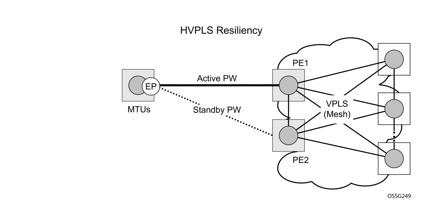
This feature provides the ability to have a node deployed as MTUs (Multi-Tenant Unit Switches) to be multi-homed for VPLS to multiple routers deployed as PEs without requiring the use of mVPLS.
In the configuration example shown in Figure 39, the MTUs have spoke-SDPs to two PEs devices. One is designated as the primary and one as the secondary spoke-SDP. This is based on a precedence value associated with each spoke. If the primary and secondary spoke-SDPs have the same precedence value, the spoke-SDP with lower ID functions as the primary SDP.
The secondary spoke is in a blocking state (both on receive and transmit) as long as the primary spoke is available. When the primary spoke becomes unavailable (due to link failure, PEs failure, etc.), the MTU immediately switches traffic to the backup spoke and starts receiving/sending traffic to/from the standby spoke. Optional revertive operation (with configurable switch-back delay) is applicable only when one of the spokes is configured with precedence of primary. If not, this action does not take place. Forced manual switchover is also supported.
To speed up the convergence time during a switchover, MAC flush is configured. The MTUs generates a MAC flush message over the newly unblocked spoke when a spoke change occurs. As a result, the PEs receiving the MAC flush will flush all MACs associated with the impacted VPLS service instance and forward the MAC flush to the other PEs in the VPLS network if “propagate-mac-flush” is enabled.
4.2.9.3. Inter-Domain VPLS Resiliency using Multi-Chassis Endpoints
| Note: MC-EP is not supported on 7210 SAS platforms. This section provides an example of how 7210 SAS devices can be used as MTU devices in an MC-EP solution. In this solution the 7750 SR routers provide the MC-EP functionality. |
Inter-domain VPLS refers to a VPLS deployment where sites may be located in different domains. An example of inter-domain deployment can be where different Metro domains are interconnected over a Wide Area Network (Metro1-WAN-Metro2) or where sites are located in different autonomous systems (AS1-ASBRs-AS2).
Multi-chassis endpoint (MC-EP) provides an alternate solution that does not require RSTP at the gateway VPLS PEs while still using pseudowires to interconnect the VPLS instances located in the two domains.
MC-EP expands the single chassis endpoint based on active-standby pseudowires for VPLS shown in Figure 40. In the solution shown by the Figure 40, 7210 devices are used as MTUs.
Figure 40: H-VPLS Resiliency Based on AS Pseudowires
The active-standby pseudowire solution is appropriate for the scenario when only one VPLS PE (MTU-s) needs to be dual-homed to two core PEs (PE1 and PE2).
4.2.10. VPLS Access Redundancy
A second application of hierarchical VPLS is using that are MPLS-enabled which must have spoke-SDPs to the closest PE node. To protect against failure of the PE node, an MTU can be dual-homed.
The following are several mechanisms that can be used to resolve a loop in an access circuit, however from operation perspective they can be subdivided into two groups:
- STP-based access, with or without mVPLS.
4.2.10.1. STP-Based Redundant Access to VPLS
In configuration shown in Figure 41, STP is activated on the MTU and two PEs to resolve a potential loop.
Figure 41: Dual Homed MTU-s in Two-Tier Hierarchy H-VPLS
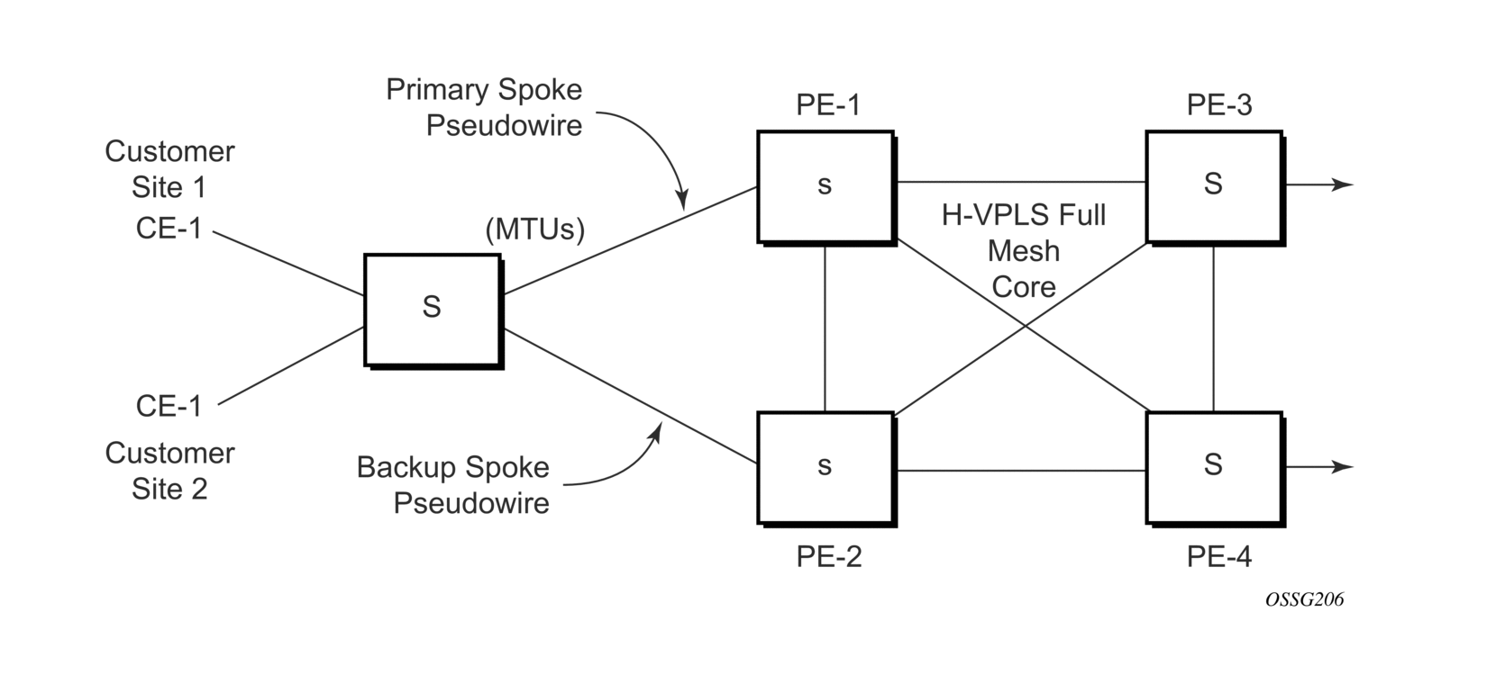
To remove such a loop from the topology, Spanning Tree Protocol (STP) can be run over the SDPs (links) which form the loop such that one of the SDPs is blocked. Running STP in every VPLS in this topology is not efficient as the node includes functionality which can associate a number of VPLSes to a single STP instance running over the redundant SDPs. Node redundancy is therefore achieved by running STP in one VPLS. Therefore, this applies the conclusions of this STP to the other VPLS services.
The VPLS instance running STP is referred to as the management VPLS or mVPLS. In the case of a failure of the active node, STP on the management VPLS in the standby node will change the link states from disabled to active. The standby node will then broadcast a MAC flush LDP control message in each of the protected VPLS instances, so that the address of the newly active node can be relearned by all PEs in the VPLS. It is possible to configure two management VPLS services, where both VPLS services have different active spokes (this is achieved by changing the path-cost in STP). By associating different user VPLSes with the two management VPLS services, load balancing across the spokes can be achieved.
In this configuration the scope of STP domain is limited to MTU and PEs, while any topology change needs to be propagated in the whole VPLS domain.
This is done by using “MAC-flush” messages defined by RFC 4762, Virtual Private LAN Services Using LDP Signaling. In the case where STP acts as a loop resolution mechanism, every Topology Change Notification (TCN) received in a context of STP instance is translated into an LDP-MAC address withdrawal message (also referred to as a MAC-flush message) requesting to clear all FDB entries except the ones learned from the originating PE. Such messages are sent to all PE peers connected through SDPs (mesh and spoke) in the context of VPLS services which are managed by the specific STP instance.
4.2.10.2. Redundant Access to VPLS without STP
The Nokia implementation also alternative methods for providing a redundant access to Layer 2 services, such as MC-LAG. Also in this case, the topology change event needs to be propagated into VPLS topology to provide fast convergence.
Figure 39 show a dual-homed connection to VPLS service (PE-A, PE-B, PE-C, PE-D) and operation in case of link failure (between PE-C and L2-B). Upon detection of a link failure PE-C will send MAC-Address-Withdraw messages, which will indicate to all LDP peers that they should flush all MAC addresses learned from PE-C. This will lead that to a broadcasting of packets addressing affected hosts and relearning process in case an alternative route exists.
Note that the message described here is different from the message described in previous section and in RFC 4762, Virtual Private LAN Services Using LDP Signaling. The difference is in the interpretation and action performed in the receiving PE. According to the standard definition, upon receipt of a MAC withdraw message, all MAC addresses, except the ones learned from the source PE, are flushed,
This section specifies that all MAC addresses learned from the source are flushed. This message has been implemented as an LDP address message with vendor-specific type, length, value (TLV), and is called the flush-mine message.
The advantage of this approach (as compared to RSTP based methods) is that only MAC-affected addresses are flushed and not the full forwarding database. While this method does not provide a mechanism to secure alternative loop-free topology, the convergence time is dependent on the speed of the specific CE device will open alternative link (L2-B switch in Figure 57) as well as on the speed PE routers will flush their FDB.
In addition, this mechanism is effective only if PE and CE are directly connected (no hub or bridge) as it reacts to physical failure of the link.
4.2.11. MAC Flush Message Processing
The previous sections described operation principle of several redundancy mechanisms available in context of VPLS service. All of them rely on MAC flush message as a tool to propagate topology change in a context of the specific VPLS. This section aims to summarize basic rules for generation and processing of these messages.
As described on respective sections, the 7210 SAS supports two types of MAC flush message, flush-all-but-mine and flush-mine. The main difference between these messages is the type of action they signal. Flush-all-but-mine requests clearing of all FDB entries which were learned from all other LDP peers except the originating PE. This type is also defined by RFC 4762 as an LDP MAC address withdrawal with an empty MAC address list.
Flush-all-mine message requests clearing all FDB entries learned from originating PE. This means that this message has exactly other effect then flush-all-but-mine message. This type is not included in RFC 4762 definition and it is implemented using vendor specific TLV.
The advantages and disadvantages of the individual types should be apparent from examples in the previous section. The description here focuses on summarizing actions taken on reception and conditions individual messages are generated.
Upon reception of MAC flush messages (regardless the type) SR-Series PE will take following actions:
- Clears FDB entries of all indicated VPLS services conforming the definition.
- Propagates the message (preserving the type) to all LDP peers, if “propagate-mac-flush” flag is enabled at corresponding VPLS level.
The flush-all-but-mine message is generated under following conditions:
- The flush-all-but-mine message is received from LDP peer and propagate-mac-flush flag is enabled. The message is sent to all LDP peers in the context of VPLS service it was received in.
- TCN message in a context of STP instance is received. The flush-all-but-mine message is sent to all LDP-peers connected with spoke and mesh SDPs in a context of VPLS service controlled by the specific STP instance (based on mVPLS definition). The message is sent only to LDP peers which are not part of STP domain, which means corresponding spoke and mesh SDPs are not part of mVPLS.
- Flush-all-but-mine message is generated when switch over between spoke SDPs of the same endpoint occurs. The message is sent to LDP peer connected through newly active spoke-SDP.
The flush-mine message is generated under following conditions:
- The flush-mine message is received from LDP peer and “propagate-mac-flush” flag is enabled. The message is sent to all LDP peers in the context of VPLS service it was received.
- The flush-mine message is generated when a SAP or SDP transitions from operationally up to an operationally down state and send-flush-on-failure flag is enabled in the context of the specific VPLS service. The message is sent to all LDP peers connected in the context of the specific VPLS service. Note, that enabling “send-flush-on-failure” the flag is blocked in VPLS service managed by mVPLS. This is to prevent both messages from being sent at the same time.
- The flush-mine message is generated when an MC-LAG SAP transitions from an operationally up state to an operationally down state. The message is sent to all LDP peers connected in the context of the specific VPLS service.
4.2.11.1. MAC Flush with STP
A second application of Hierarchical VPLS is in the use of Multi Tenant Units (MTU). MTUs are typically not MPLS-enabled, and therefore have Ethernet links to the closest PE node (see Figure 42). To protect against failure of the PE node, an MTU could be dual-homed and therefore have two SAPs on two PE nodes. To resolve the potential loop, STP is activated on the MTU and the two PEs.
Like in the preceding scenario, STP only needs to run in a single VPLS instance, and the results of the STP calculations are applied to all VPLSs on the link. Equally, the standby node will broadcast MAC flush LDP messages in the protected VPLS instances when it detects that the active node has failed.
Figure 42: H-VPLS with SAP Redundancy
4.2.11.2. Selective MAC Flush
When using STP as described previously is not appropriate, the “Selective MAC flush” feature can be used instead.
In this scenario, the 7210 SAS-M that detects a port failure will send out a flush-all-from-ME LDP message to all PEs in the VPLS. The PEs receiving this LDP message will remove all MAC entries originated by the sender from the indicated VPLS.
A drawback of this approach is that selective MAC flush does not signal that a backup path was found, only that the previous path is no longer available. In addition, the selective MAC Flush mechanism is effective only if the CE and PE are directly connected (no intermediate hubs or bridges) as it reacts only to a physical failure of the link. Consequently, Nokia recommends using the MAC flush with STP method described previously where possible.
4.2.11.3. Dual Homing to a VPLS Service
Figure 43 shows a dual-homed connection to VPLS service (PE-A, PE-B, PE-C, PE-D) and operation in case of link failure (between PE-C and L2-B). Upon detection of a link failure PE-C will send MAC-Address-Withdraw messages, which will indicate to all LDP peers that they should flush all MAC addresses learned from PE-C. This will lead that to a broadcasting of packets addressing affected hosts and relearning process in case an alternative route exists.
Figure 43: Dual Homed CE Connection to VPLS
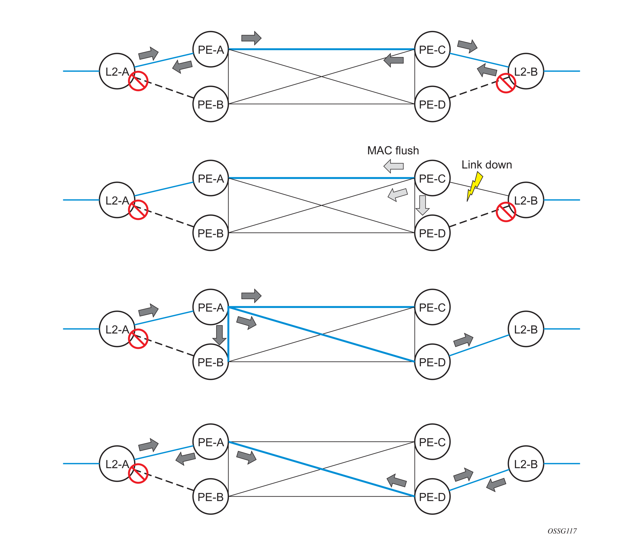
Note that the message described here is different from the message described in draft-ietf-l2vpn-vpls-ldp-xx.txt, Virtual Private LAN Services over MPLS. The difference is in the interpretation and action performed in the receiving PE. According the draft definition, upon receipt of a MAC-withdraw message, all MAC addresses, except the ones learned from the source PE, are flushed, This section specifies that all MAC addresses learned from the source are flushed. This message has been implemented as an LDP address message with vendor-specific type, length, value (TLV), and is called the flush-all-from-ME message.
The draft definition message is currently used in management VPLS which is using RSTP for recovering from failures in Layer 2 topologies. The mechanism described in this document represent an alternative solution.
The advantage of this approach (as compared to RSTP based methods) is that only MAC-affected addresses are flushed and not the full forwarding database. While this method does not provide a mechanism to secure alternative loop-free topology, the convergence time is dependent on the speed of the specific CE device will open alternative link (L2-B switch in Figure 43) as well as on the speed PE routers will flush their FDB.
In addition, this mechanism is effective only if PE and CE are directly connected (no hub or bridge) as it reacts to physical failure of the link.
4.2.12. VPLS Service Considerations
This section describes various 7210 SAS service features and any special capabilities or considerations as they relate to VPLS services.
4.2.12.1. SAP Encapsulations
VPLS services are designed to carry Ethernet frame payloads, so it can provide connectivity between any SAPs that pass Ethernet frames. The following SAP encapsulations are supported on the VPLS service:
- Ethernet null
- Ethernet Dot1q
- Ethernet Dot1q Default
- Ethernet Dot1q Explicit Null
4.2.12.2. VLAN Processing
The SAP encapsulation definition on Ethernet ingress ports defines which VLAN tags are used to determine the service that the packet belongs:
- Null encapsulation defined on ingress — Any VLAN tags are ignored and the packet goes to a default service for the SAP.
- Dot1q encapsulation defined on ingress — Only first VLAN tag is considered.
- Dot1q Default encapsulation defined on ingress — Tagged packets not matching any of the configured VLAN encapsulations would be accepted. This is like a default SAP for tagged packets.
- Dot1q Explicit Null encapsulation defined on ingress — Any untagged or priority tagged packets will be accepted.
4.3. BGP Auto-Discovery for LDP VPLS
BGP Auto Discovery (BGP AD) for LDP VPLS is a framework for automatically discovering the endpoints of a Layer 2 VPN offering an operational model similar to that of an IP VPN. This model allows carriers to leverage existing network elements and functions, including but not limited to, route reflectors and BGP policies to control the VPLS topology.
BGP AD is an excellent complement to an already established and well deployed Layer 2 VPN signaling mechanism target LDP providing one touch provisioning for LDP VPLS where all the related PEs are discovered automatically. The service provider may make use of existing BGP policies to regulate the exchanges between PEs in the same, or in different, autonomous system (AS) domains. The addition of BGP AD procedures does not require carriers to uproot their existing VPLS deployments and to change the signaling protocol.
4.3.1. BGP AD Overview
The BGP protocol establishes neighbor relationships between configured peers. An open message is sent after the completion of the three-way TCP handshake. This open message contains information about the BGP peer sending the message. This message contains Autonomous System Number (ASN), BGP version, timer information and operational parameters, including capabilities. The capabilities of a peer are exchanged using two numerical values: the Address Family Identifier (AFI) and Subsequent Address Family Identifier (SAFI). These numbers are allocated by the Internet Assigned Numbers Authority (IANA). BGP AD uses AFI 65 (L2VPN) and SAFI 25 (BGP VPLS).
4.3.2. Information Model
Following is the establishment of the peer relationship, the discovery process begins as soon as a new VPLS service instance is provisioned on the PE.
Two VPLS identifiers are used to indicate the VPLS membership and the individual VPLS instance:
- VPLS-ID — Membership information, unique network wide identifier; same value assigned for all VPLS switch instances (VSIs) belonging to the same VPLS; encodable and carried as a BGP extended community in one of the following formats:
- A two-octet AS specific extended community
- An IPv4 address specific extended community
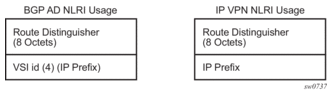
- VSI-ID— The unique identifier for each individual VSI, built by concatenating a route distinguisher (RD) with a 4 bytes identifier (usually the system IP of the VPLS PE); encoded and carried in the corresponding BGP NLRI.
To advertise this information, BGP AD employs a simplified version of the BGP VPLS NLRI where just the RD and the next 4 bytes are used to identify the VPLS instance. There is no need for Label Block and Label Size fields as T-LDP will take care of signaling the service labels later on.
The format of the BGP AD NLRI is very similar with the one used for IP VPN, as shown in Figure 44. The system IP may be used for the last 4 bytes of the VSI-ID further simplifying the addressing and the provisioning process.
Figure 44: BGP AD NLRI versus IP VPN NLRI
Network Layer Reachability Information (NLRI) is exchanged between BGP peers indicating how to reach prefixes. The NLRI is used in the Layer 2 VPN case to tell PE peers how to reach the VSI rather than specific prefixes. The advertisement includes the BGP next hop and a route target (RT). The BGP next hop indicates the VSI location and is used in the next step to determine which signaling session is used for pseudowire signaling. The RT, also coded as an extended community, can be used to build a VPLS full mesh or a H-VPLS hierarchy through the use of BGP import or export policies.
BGP is only used to discover VPN endpoints and the corresponding far end PEs. It is not used to signal the pseudowire labels. This task remains the responsibility of targeted-LDP (T-LDP).
4.3.3. FEC Element for T-LDP Signaling
Two LDP FEC elements are defined in RFC 4447, PW Setup & Maintenance Using LDP. The original pseudowire-ID FEC element 128 (0x80) employs a 32-bit field to identify the virtual circuit ID and it was used extensively in the initial VPWS and VPLS deployments. The simple format is easy to understand but it does not provide the required information model for BGP Auto-Discovery function. To support BGP AD and other new applications a new Layer 2 FEC element, the generalized FEC (0x81) is required.
The generalized pseudowire-ID FEC element has been designed for auto discovery applications. It provides a field, the address group identifier (AGI), that is used to signal the membership information from the VPLS-ID. Separate address fields are provided for the source and target address associated with the VPLS endpoints called the Source Attachment Individual Identifier (SAII) and respectively, Target Attachment Individual Identifier (TAII). These fields carry the VSI-ID values for the two instances that are to be connected through the signaled pseudowire.
The detailed format for FEC 129 is shown in Figure 45.
Figure 45: Generalized Pseudowire-ID FEC Element
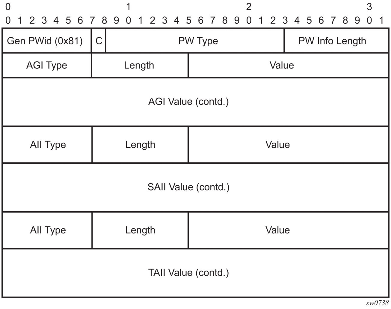
Each of the FEC fields are designed as a sub-TLV equipped with its own type and length providing support for new applications. To accommodate the BGP AD information model the following FEC formats are used:
- AGI (type 1) is identical in format and content with the BGP extended community attribute used to carry the VPLS-ID value.
- Source AII (type 1) is a 4 bytes value destined to carry the local VSI-id (outgoing NLRI minus the RD).
- Target AII (type 1) is a 4 bytes value destined to carry the remote VSI-ID (incoming NLRI minus the RD).
4.3.4. BGP-AD and Target LDP (T-LDP) Interaction
BGP is responsible for discovering the location of VSIs that share the same VPLS membership. LDP protocol is responsible for setting up the pseudowire infrastructure between the related VSIs by exchanging service specific labels between them.
When the local VPLS information is provisioned in the local PE, the related PEs participating in the same VPLS are identified through BGP AD exchanges. A list of far-end PEs is generated and triggers the creation, if required, of the necessary T-LDP sessions to these PEs and the exchange of the service specific VPN labels. The steps for the BGP AD discovery process and LDP session establishment and label exchange are shown in Figure 46.
Figure 46: BGP-AD and T-LDP Interaction
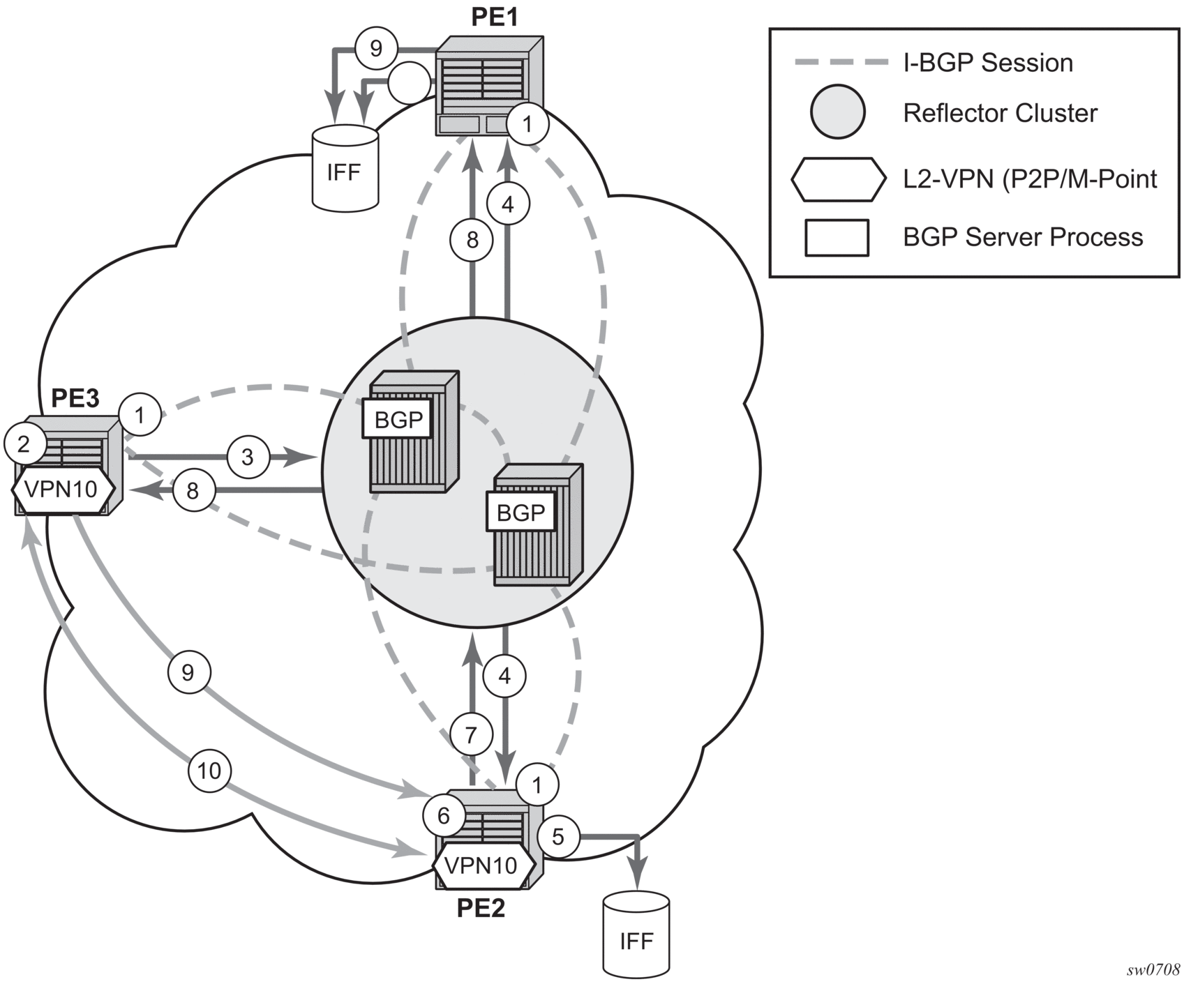
Key:
- Establish I-BGP connectivity RR.
- Configure VPN (10) on edge node (PE3).
- Announce VPN to RR using BGP-AD.
- Send membership update to each client of the cluster.
- LDP exchange or inbound FEC filtering (IFF) of non-match or VPLS down.
- Configure VPN (10) on edge node (PE2).
- Announce VPN to RR using BGP-AD.
- Send membership update to each client of the cluster.
- LDP exchange or inbound FEC filtering (IFF) of non-match or VPLS down.
- Complete LDP bidirectional pseudowire establishment FEC 129.
4.3.5. SDP Usage
Service Access Points (SAP) are linked to transport tunnels using Service Distribution Points (SDP). The service architecture of the 7210 platform allows services to be abstracted from the transport network.
MPLS transport tunnels are signaled using the Resource Reservation Protocol (RSVP-TE) or by the Label Distribution Protocol (LDP). The capability to automatically create an SDP only exists for LDP based transport tunnels. Using a manually provisioned SDP is available for both RSVP-TE and LDP transport tunnels. Refer to the 7210 SAS-M, T, R6, R12, Mxp, Sx, S MPLS Guide for more information about MPLS, LDP, and RSVP.
4.3.6. Automatic Creation of SDPs
When BGP AD is used for LDP VPLS and LDP is used as the transport tunnel there is no requirement to manually create an SDP. The LDP SDP can be automatically instantiated using the information advertised by BGP AD. This simplifies the configuration on the service node.
Enabling LDP on the IP interfaces connecting all nodes between the ingress and the egress, builds transport tunnels based on the best IGP path. LDP bindings are automatically built and stored in the hardware. These entries contain an MPLS label pointing to the best next hop along the best path toward the destination.
When two endpoints need to connect and no SDP exists, a new SDP will automatically be constructed. New services added between two endpoints that already have an automatically created SDP will be immediately used. No new SDP will be constructed. The far-end information is gleaned from the BGP next hop information in the NLRI. When services are withdrawn with a BGP_Unreach_NLRI, the automatically established SDP will remain up as long as at least one service is connected between those endpoints. An automatically created SDP will be removed and the resources released when the only or last service is removed.
4.3.7. Manually Provisioned SDP
The carrier is required to manually provision the SDP if they create transport tunnels using RSVP-TE. Operators have the option to choose a manually configured SDP, if they use LDP as the tunnel signaling protocol. The functionality is the same regardless of the signaling protocol.
Creating a BGP-AD enabled VPLS service on an ingress node with the manually provisioned SDP option causes the Tunnel Manager to search for an existing SDP that connects to the far-end PE. The far-end IP information is gleaned from the BGP next hop information in the NLRI. If a single SDP exists to that PE, it is used. If no SDP is established between the two endpoints, the service remains down until a manually configured SDP becomes active.
When multiple SDPs exist between two endpoints, the tunnel manager selects the appropriate SDP. The algorithm preferred SDPs with the best (lower) metric. Should there be multiple SDPs with equal metrics, the operational state of the SDPs with the best metric is considered. If the operational state is the same, the SDP with the higher SDP ID is used. If an SDP with a preferred metric is found with an operational state that is not active, the tunnel manager flags it as ineligible and restarts the algorithm.
4.3.8. Automatic Instantiation of Pseudowires (SDP Bindings)
The choice of manual or auto provisioned SDPs has limited impact on the amount of required provisioning. Most of the savings are achieved through the automatic instantiation of the pseudowire infrastructure (SDP bindings). This is achieved for every auto-discovered VSIs through the use of the pseudowire template concept. Each VPLS service that uses BGP AD contains the “pw-template-binding” option defining specific Layer 2 VPN parameters. This command references a “pw-template” which defines the pseudowire parameters. The same “pwtemplate” may be referenced by multiple VPLS services. As a result, changes to these pseudowire templates have to be treated with great care as they may impact many customers at once.
The Nokia implementation provides for safe handling of pseudowire templates. Changes to the pseudowire templates are not automatically propagated. Tools are provided to evaluate and distribute the changes. The following command is used to distribute changes to a “pw-template” at the service level to one or all services that use that template.
PERs-4# tools perform service id 300 eval-pw-template 1 allow-service-impact
If the service ID is omitted, then all services are updated. The type of change made to the “pwtemplate” influences how the service is impacted.
- Adding or removing a split-horizon-group will cause the router to destroy the original object and recreate using the new value.
- Changing parameters in the vc-type {ether | vlan} command requires LDP to resignal the labels.
Both of these changes affect the services. Other changes are not service affected.
4.3.9. Mixing Statically Configured and Auto-Discovered Pseudowires in a VPLS Service
The services implementation allows for manually provisioned and auto-discovered pseudowire (SDP bindings) to co-exist in the same VPLS instance (for example, both FEC128 and FEC 129 are supported). This allows for gradual introduction of auto discovery into an existing VPLS deployment.
As FEC 128 and 129 represent different addressing schemes, it is important to make sure that only one is used at any point in time between the same two VPLS instances. Otherwise, both pseudowires may become active causing a loop that might adversely impact the correct functioning of the service. Nokia recommends that the FEC128 pseudowire be disabled as soon as the FEC129 addressing scheme is introduced in a portion of the network. Alternatively, RSTP may be used during the migration as a safety mechanism to provide additional protection against operational errors.
4.3.10. Resiliency Schemes
The use of BGP-AD on the network side, or in the backbone, does not affect the different resiliency schemes Nokia has developed in the access network. This means that both Multi-Chassis Link Aggregation (MC-LAG) and Management-VPLS (M-VPLS) can still be used.
BGP-AD may co-exist with Hierarchical-VPLS (H-VPLS) resiliency schemes (for example, dual homed MTU-s devices to different PE-rs nodes) using existing methods (M-VPLS and statically configured Active or Standby pseudowire endpoint).
If provisioned SDPs are used by BGP AD, M-VPLS may be employed to provide loop avoidance. However, it is currently not possible to auto-discover active or standby pseudowires and to instantiate the related endpoint.
4.4. Routed VPLS
Routed VPLS (RVPLS) allows a VPLS instance to be associated with an IES IP interface.
Within an RPVLS service, traffic with a destination MAC matching that of the associated IP interface is routed based on the IP forwarding table; all other traffic is forwarded based on the VPLS forwarding table.
In network mode, RVPLS service can be associated with an IPv4 interface and supports static routing and other routing protocols. It can be used to provide a service to the customer or for inband management of the node.
4.4.1. IES or VPRN IP Interface Binding
A standard IP interface within an existing IES or VPRN service context may be bound to a service name. A VPLS service only supports binding for a single IP interface.
While an IP interface may only be bound to a single VPLS service, the routing context containing the IP interface (IES) may have other IP interfaces bound to other VPLS service contexts. That is, Routed VPLS allows the binding of IP interfaces in IES services to be bound to VPLS services.
4.4.2. Assigning a Service Name to a VPLS Service
When a service name is applied to any service context, the name and service ID association is registered with the system. A service name cannot be assigned to more than one service ID. Special consideration is given to a service name that is assigned to a VPLS service that has the configure>service>vpls>allow-ip-int-binding command is enabled. If a name is applied to the VPLS service while the flag is set, the system scans the existing IES services for an IP interface that is bound to the specified service name. If an IP interface is found, the IP interface is attached to the VPLS service associated with the name. Only one interface can be bound to the specified name.
If the allow-ip-int-binding command is not enabled on the VPLS service, the system does not attempt to resolve the VPLS service name to an IP interface. As soon as the allow-ip-int-binding flag is configured on the VPLS, the corresponding IP interface is adhered and become operational up. There is no need to toggle the shutdown or no shutdown command.
If an IP interface is not currently bound to the service name used by the VPLS service, no action is taken at the time of the service name assignment.
4.4.3. Service Binding Requirements
In the event that the defined service name is created on the system, the system checks to ensure that the service type is VPLS. If the created service type is VPLS, the IP interface is eligible to enter the operationally upstate.
4.4.3.1. Bound Service Name Assignment
In the event that a bound service name is assigned to a service within the system, the system first checks to ensure the service type is VPLS. Secondly the system ensures that the service is not already bound to another IP interface through the service name. If the service type is not VPLS or the service is already bound to another IP interface through the service ID, the service name assignment fails.
A single VPLS instance cannot be bound to two separate IP interfaces.
4.4.3.2. Binding a Service Name to an IP Interface
An IP interface within an IES or VPRN service context may be bound to a service name at anytime. Only one interface can be bound to a service. When an IP interface is bound to a service name and the IP interface is administratively up, the system scans for a VPLS service context using the name and takes the following actions:
- If the name is not currently in use by a service, the IP interface is placed in an operationally down: Non-existent service name or inappropriate service type state.
- If the name is currently in use by a non-VPLS service or the wrong type of VPLS service, the IP interface is placed in the operationally down: Non-existent service name or inappropriate service type state.
- If the name is currently in use by a VPLS service without the allow-ip-int-binding flag set, the IP interface is placed in the operationally down: VPLS service allow-ip-intbinding flag not set state. There is no need to toggle the shutdown or no shutdown command.
- If the name is currently in use by a valid VPLS service and the allow-ip-int-binding flag is set, the IP interface is eligible to be placed in the operationally up state depending on other operational criteria being met.
4.4.4. Routed VPLS Specific ARP Cache Behavior
In typical routing behavior, the system uses the IP route table to select the egress interface, an ARP entry is used forward the packet to the appropriate Ethernet MAC. With routed VPLS, the egress IP interface may be represented by multiple egress (VPLS service SAPs).
Table 39 describes how the ARP cache and MAC FIB entry states interact.
Table 39: Routing Behavior in RVPLS and Interaction ARP Cache and MAC FIB
ARP Cache Entry | MAC FIB Entry | Routing or System Behavior |
ARP Cache Miss (No Entry) | Known or Unknown | Triggers a request to control plane ARP processing module, to send out an ARP request, out of all the SAPs. (also known as virtual ports) of the VPLS instance. |
ARP Cache Hit | Known | Forward to specific VPLS virtual port or SAP. |
Unknown | This behavior cannot happen typically in 7210 SAS, as and when a L2 entry is removed from the FDB, the matching MAC address is also removed from the ARP cache. |
4.4.4.1. The allow-ip-int-binding VPLS Flag
The allow-ip-int-binding flag on a VPLS service context is used to inform the system that the VPLS service is enabled for routing support. The system uses the setting of the flag as a key to determine what type of ports the VPLS service may span.
The system also uses the flag state to define which VPLS features are configurable on the VPLS service to prevent enabling a feature that is not supported when routing support is enabled.
4.4.5. Routed VPLS SAPs only Supported on Standard Ethernet Ports
The allow-ip-int-binding flag is set (routing support enabled) on a VPLS service. SAPs within the service can be created on standard Ethernet ports.
4.4.5.1. LAG Port Membership Constraints
If a LAG has a non-supported port type as a member, a SAP for the routing-enabled VPLS service cannot be created on the LAG. When one or more routing enabled VPLS SAPs are associated with a LAG, a non-supported Ethernet port type cannot be added to the LAG membership.
4.4.5.2. VPLS Feature Support and Restrictions
When the allow-ip-int-binding flag is set on a VPLS service, the following features cannot be enabled (the flag also cannot be enabled while any of these features are applied to the VPLS service):
- In network mode, SDPs used in spoke or mesh SDP bindings cannot be configured.
- In network mode, the VPLS service type must be RVPLS; no other VPLS service is allowed.
- MVR from an RVPLS SAP to another SAP is not supported.
- Default QinQ SAPs are not supported in an RVPLS service.
- The allow-ip-int-binding command cannot be used in a VPLS service that is acting as the G.8032 control instance.
- IPv4 filters (ingress and egress) can be used with RVPLS SAPs. Additionally IP ingress override filters are supported, which affects the behavior of the IP filters attached to the RVPLS SAPs.
- MAC filters (ingress and egress) are not supported for use with RVPLS SAPs.
- A VPLS IP interface is not allowed in an RVPLS service, and an RVPLS service/SAP cannot be configured with a VPLS IP interface.
- In network mode, the RVPLS service can be configured only with access SAPs or with SAPs on hybrid ports (applies only to the 7210 SAS-R6 and 7210 SAS-R12).
- In network mode, the VPLS service can use the following svc-sap-type values: any, null-star, and dot1q-preserve.
- G.8032 or MVPLS/STP based protection mechanisms can be used with an RPVLS service. A separate G.8032 control instance or a separate MVPLS/STP instance must be used and the RVPLS SAPs must be associated with these control instances such that the RVPLS SAP forwarding state is driven by the control instance protocols
- IP multicast is not supported in an RVPLS service.
- IGMP snooping is supported in an RVPLS service for 7210 SAS-R6 and 7210 SAS-R12.
- DHCP snooping is not supported for the SAPs configured in an RVPLS service. Instead, DHCP relay can be enabled on the IES service associated with the RVPLS service.
- In network mode, an RVPLS SAP drops packets received with extra tags. That is, if a packet is received on a RVPLS SAP, with number of tags greater than the SAP tags to which it is mapped, then it is dropped. This is true for all supported encapsulations (that is, null, dot1q, and QinQ encapsulations) of the port. For example, double-tagged packets received on a dot1q SAP configured in a RVPLS service is dropped on ingress.
4.4.6. VPLS SAP Ingress IP Filter Override
When an IP Interface is attached to a VPLS service context, the VPLS SAP provisioned IP filter for ingress routed packets may be optionally overridden to provide special ingress filtering for routed packets. This allows different filtering for routed packets and non-routed packets. The filter override is defined on the IP interface bound to the VPLS service name. A separate override filter may be specified for IPv4 packet types.
If a filter for a specific packet type (IPv4) is not overridden, the SAP specified filter is applied to the packet (if defined).
Table 40 and Table 41 list ACL lookup behavior with and without ingress override filter attached to an IES interface in a RVPLS service.
Table 40: ACL Lookup Behavior with Ingress Override Filter Attached to an IES Interface in an RVPLS Service
Type of Traffic | SAP Ingress IPv4 Filter | SAP Egress IPv4 Filter | Ingress Override IPv4 Filter |
Destination MAC != IES IP interface MAC | Yes | Yes | No |
Destination MAC = IES IP interface MAC and Destination IP on same subnet as IES interface | No | No | Yes |
Destination Mac = IES IP interface mac and destination IP not on same subnet as IES IP interface and route to destination IP does not exist | No | No | No |
Destination Mac = IES IP interface mac and destination IP not on same subnet as IES IP interface and route to destination IP exists | No | No | Yes |
Destination MAC = IES IP interface MAC and IP TTL = 1 | No | No | No |
Destination MAC = IES IP interface MAC and IPv4 packet with Options | No | No | No |
Destination MAC = IES IP interface MAC and IPv4 Multicast packet | No | No | No |
Table 41: ACL Lookup Behavior without Ingress Override Filter Attached to an IES Interface in an RVPLS Service
Type of Traffic | SAP Ingress IPv4 Filter | SAP Egress IPv4 Filter |
Destination MAC != IES IP interface MAC | Yes | Yes |
Destination MAC = IES IP interface MAC and Destination IP on same subnet as IES IP interface | Yes | No |
Destination Mac = IES IP interface mac and destination IP not on same subnet as IES IP interface and route to destination IP does not exist | No | No |
Destination Mac = IES IP interface MAC and destination IP not on same subnet as IES IP interface and route to destination IP exists | Yes | No |
Destination MAC = IES IP interface MAC and IP TTL = 1 | No | No |
Destination MAC = IES IP interface MAC and IPv4 packet with Options | No | No |
Destination MAC = IES IP interface MAC and IPv4 Multicast packet | No | No |
4.4.6.1. QoS Support for VPLS SAPs and IP Interface in a Routed VPLS Service
- SAP ingress classification (IPv4 and MAC criteria) is supported for SAPs configured in the service. SAP ingress policies cannot be associated with IES IP interface.
- On 7210 SAS-R6 and 7210 SAS-R12, when the node is operating in SAP based queuing mode, unicast traffic sent out of RVPLS SAPs uses SAP based egress queues while BUM traffic sent out of RVPLS SAPs uses per port egress queues. When the 7210 SAS-R6 and 7210 SAS-R12 node is operating in port based queuing mode, both unicast and BUM traffic sent out of RVPLS SAPS uses per port egress queues. For more information, refer to the 7210 SAS-R6, R12 Quality of Service Guide.
- Port based Egress Marking is supported for both routed packets and bridged packets. The existing access egress QoS policy can be used for Dot1p marking and DSCP marking.
4.4.6.2. Routed VPLS Supported Routing Related Protocols
In network mode RPVLS is supported only in the base routing instance. Only IPv4 addressing support is available for IES and VPRN interfaces associated with Routed VPLS service. Table 42 lists the support available for routing protocols on IP interfaces bound to a VPLS service in network mode.
Table 42: Routing Protocols on IP Interfaces Bound to a VPLS Service
Services | Network |
Static-routing | Supported |
BGP | Not Supported |
OSPF | Supported |
ISIS | Supported |
BFD | Supported |
VRRP | Supported |
ARP and Proxy-Arp | Both are supported |
DHCP Relay 1 | Supported |
- DHCP relay can be configured for the IES interface associated with the Routed VPLS service. DHCP snooping cannot be configured on the VPLS SAPs in the routed VPLS Service.
Note:
4.4.6.3. Spanning Tree and Split Horizon
An R-VPLS context supports all spanning tree capabilities that a non-routed VPLS service supports. Service-based SHGs are not supported in an R-VPLS context.
4.4.7. Routed VPLS and IGMPv3 Snooping
This feature (IGMPv3 snooping in RVPLS) extends IGMP snooping to a routed VPLS service. On 7210 SAS, VPLS services that use MPLS uplinks (network mode) support IGMP snooping with IGMP v1 and v2 only. That is, IGMP v3 is not supported, which means that only Layer 2 multicast is supported. To support source-based IP multicast, support for IGMPv3 is needed. To provide source-based IP multicast, support for IGMP snooping v1, v2, and v3 is added to routed VPLS service. The IGMPv3 snooping in RVPLS feature gives customers an option to use a routed VPLS service without a configured IP interface association to deliver IP multicast traffic in access Layer 2 networks. Users also have an option to configure MVR service.
IGMPv3 snooping in RVPLS is supported only for IES (not for VPRNs).
For information about IGMP snooping in the context of VPLS, see IGMP Snooping in VPLS Service.
4.4.7.1. Configuration Guidelines and Restrictions for IGMP Snooping in RVPLS
The following items apply to IGMP snooping in RVPLS and should be included with the regular VPLS multicast configuration guidelines (see Configuration Guidelines for IGMP Snooping in VPLS Service and Routed VPLS Supported Functionality and Restrictions):
- RVPLS without an IP interface association can be used to emulate VPLS service with support for IGMPv3 snooping.
- RVPLS with or without IP interface association can be used for IGMPv3 snooping. If enabling MVR on the service then the service should not have an IP interface association.
- IGMPv3 snooping can be enabled in the context of the RVPLS (both with and without MVR). It cannot be enabled in regular VPLS service. Regular VPLS service supports IGMP v1 and v2 only.
- MVR can be configured in an RVPLS without an IP interface association. It can be used to leak multicast traffic to a user RVPLS service with an IP interface configuration. Therefore, a user RVPLS can be used to forward both unicast and multicast services.
In addition, the following list of guidelines and restrictions pertain to IGMP snooping in an RVPLS service:
- RVPLS service can only have a single SAP per port configured in a service. That is, two SAPs on the same port cannot be configured in the same service.
- Spoke SDPs and mesh SDPs cannot be configured in an RVPLS service.
- On 7210 SAS devices, on ingress of a port, multicast traffic can be processed in the context of either igmp-snooping (Layer 2 Ethernet multicast with IGMP v1 or v2 snooping) or l3-multicast (either multicast in an Layer 3 service or IGMP snooping in an RVPLS), but not both. That is, it is not possible to configure SAPs on the port such that one SAP is a receiver for multicast traffic to be processed by IGMP snooping, and another SAP is a receiver for multicast traffic to be processed by IP multicast in the context of Layer 3 service or RVPLS. An option per port is available using the configure> port> ethernet> multicast-ingress {l2-mc | ip-mc} command to enable one or the other. Refer to the 7210 SAS-M, T, R6, R12, Mxp, Sx, S Interface Configuration Guide for more information about this command. By default, IGMP snooping is enabled to be backward compatible. Users need to explicitly change the IGMP snooping configuration to allow processing of received multicast traffic as IP multicast in the context of Layer 3 service or RVPLS.
- If a VPLS SAP is configured on the same port as the port on which IP multicast is enabled, then multicast traffic received on the SAP is dropped. Unicast, broadcast, and unknown-unicast packets received on the SAP are forwarded appropriately. This behavior is true only for VPLS SAPs and does not apply to VPLS SDPs, Epipe SAPs, and Epipe SDPs.
- With RVPLS multicast, a port on which receivers are present can be configured to perform either Layer 2 multicast replication (that is, no IP TTL decrement and no source MAC replacement) or Layer 3 multicast replication (that is, IP TTL is decremented and source MAC is replaced with 7210 SAS chassis MAC or IP interface MAC). An option to use either Layer 2 or Layer 3 multicast replication is available using the configure> port> ethernet> multicast-egress {l2-switch | l3-forward} command. Refer to the7210 SAS-M, T, R6, R12, Mxp, Sx, S Interface Configuration Guide for more information about this command. All SAPs on the port have the same behavior.
- An MVR RVPLS must be configured without an IP interface and will support Layer 2 forwarding of both unicast and multicast traffic (that is, no IP forwarding).
- A user RPVLS can be configured with an IP interface and will support Layer 2 forwarding of both unicast and multicast (with (S,G) IP multicast replications) and support Layer 3 forwarding of unicast traffic.
- On 7210 SAS-Mxp and 7210 SAS-R6, when using SAP-based egress queues and scheduler, RVPLS BUM traffic uses per port egress queues—not per SAP egress queues.
- In an MVR configuration, the svc-sap-type of the RVPLS service that is the source (also known as MVR RVPLS service) and the svc-sap-type of the RVPLS service that is the sink (also known as user RVPLS service) should match.
- On 7210 SAS-R6 and 7210 SAS-R12, the MVR RVPLS service configured with IGMPv3 snooping shares resources with TWAMP. An increase in one decreases the amount of resources available for the other. Contact your Nokia representative for more information about scaling of these features.
4.4.8. Routed VPLS Supported Functionality and Restrictions
Routed VPLS supported functionality and restrictions for network mode are specified as follows.
- Static ARP cannot be configured with an IES IP interface that is associated with an RPVLS, though static MAC can be configured in an RPVLS service.
- In network mode, both static routing and dynamic routing protocols are supported.
- Whenever a VPLS FIB entry is removed either due to user action, aging or mac-move, the corresponding ARP entry whose MAC address matches that of the MAC in the FIB is removed from the ARP cache.
- In network mode RPVLS is supported only in the base routing instance. Only IPv4 addressing support is available for IES interfaces associated with Routed VPLS service.
- IPv6 addressing support is not available for IES interface associated with RPVLS service.
- In network mode, RPVLS service cannot be bound to an VPRN Service.
- In both network mode, multiple SAPs configured on the same port cannot be part of the same RPVLS Service. That is, a single service can only be configured with a single SAP on a specific port.
- Service MTU configuration is not supported in the RPVLS service.
- In network mode, in 'any' service (that is, svc-sap-type set to any), null SAP accepts only untagged packets. Tagged packets received are dropped.
- In network mode, MPLS protocols (For example: RSVP, LDP) cannot be enabled on RPVLS IP interface
- In network mode, MPLS-TP cannot use RPVLS, IES, and IP interface.
- In network mode, RPVLS SAPS can be configured on a MC-LAG LAG.
- The discard-unknown feature is not supported in the VPLS service associated with RPVLS (only on 7210 SAS-R6 and 7210 SAS-R12).
- In the saved configuration file, for the RVPLS service, the RVPLS service instance appears twice, once for service creation and once with all the other configuration parameters. This is required to resolve references to the RVPLS service and to execute the configuration without any errors.
- Service-based SHGs are not supported in an R-VPLS service.