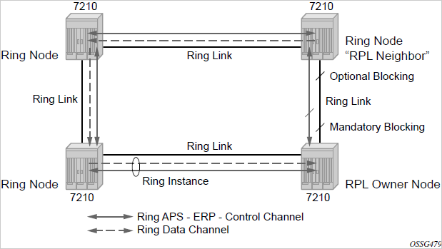
R-APS messages that carry the G.8032 protocol are sent on a dedicated protocol VLAN called ERP VLAN (or ring control instance). In a revertive case, G.8032 protocol ensures that one Ring Protection Link (RPL) owner blocks the RPL link. R-APS messages are periodically sent around in both directions to inform other nodes in the ring about the blocked port in the RPL owner node. In non-revertive mode, any link may be the RPL link.
Y.1731 Ethernet OAM CC is the basis of the R-APS messages. Y.1731 CC messages are typically used by nodes in the ring to monitor the health of each link in the ring in both directions. However, CC messages are not mandatory. Other link layer mechanisms could be considered; for example, LOS (Loss of Signal) when the nodes are directly connected.
Initially, each Ring Node blocks one of its links and notifies other nodes in the ring about the blocked link. When a ring node in the ring learns that another link is blocked, the node unblocks its blocked link, possibly causing FDB flush in all links of the ring for the affected service VLANs, controlled by the ring control instance. This procedure results in unblocking all links except the one link and the ring normal (or idle) state is reached.
In revertive mode, the RPL link will be the link that is blocked when all links are operable after the revert time. In non-revertive mode, the RPL link is no different from other ring links. Revertive mode provides predictability, particularly when there are multiple ring instances, and the operator can control which links are blocked on the different instances. Each time that there is a topology change that affects Reachability, the nodes may flush the FDB and MAC learning takes place for the affected service VLANs, allowing forwarding of packets to continue. The following figure shows this initial operational state:

When a ring failure occurs, a node or nodes detecting the failure (enabled by Y.1731 OAM CC monitoring) sends R-APS message in both directions. This allows the nodes at both ends of the failed link to block forwarding to the failed link, preventing it from becoming active. In revertive mode, the RPL owner then unblocks the previously blocked RPL and triggers an FDB flush for all nodes for the affected service instances. The ring is now in protecting state and full ring connectivity is restored. MAC learning takes place to allow Layer 2 packet forwarding on a ring. The following figure shows the failed link scenario.

When the failed link recovers, the nodes that blocked the link again send the R-APS messages indicating no failure this time. This causes the RPL owner to block the RPL link and indicate the blocked RPL link to the ring in R-APS message, when received by the nodes at the recovered link cause them to unblock that link and restore connectivity (again all nodes in the ring perform an FDB flush and MAC learning takes place). The ring is back in the normal (or idle) state.
Within each path, Y.1731 Maintenance Entity Group (MEG) Endpoints (MEPs) are used to exchange R-APS specific information (specifically to coordinate switchovers) as well as optionally fast Continuity Check Messages (CCMs), providing an inherent failure detection mechanism as part of the protocol. Failure detection of a ring path by one of the mechanisms activates the protection links. Upon failure, reconvergence times are dependent on the failure detection mechanisms.
In the case of Y.1731, the CCM transmit interval determines the response time. The 7210 SAS device supports 100 ms message timers that allow for quicker restoration times. Alternatively, 802.3ah (Ethernet in the First Mile) or LOS can trigger a protection switch where appropriate. In the case of direct connectivity between the nodes, there is no need to use Ethernet CC messaging for liveliness detection.
Revertive and non-revertive behaviors are supported. The RPL is configured and Eth-rings can be configured to revert to the RPL upon recovery.
G.8032 supports multiple data channels (VIDs) or instances per ring control instance (R-APS tag). G.8032 also supports multiple control instances such that each instance can support RPLs on different links, providing for a load balancing capability. However when services have been assigned to one instance, the rest of the services that need to be interconnected with those services must be on the same instance. That is, each data instance is a separate data VLAN on the same physical topology. When there is any one link failure or any one node failure in the ring, G.8032 protocols are capable of restoring traffic between all remaining nodes in these data instances.
Ethernet R-APS can be configured on any port configured for access mode using dot1q, QinQ encapsulation, enabling support for Ethernet R-APS protected services on the service edge toward the customer site, or within the Ethernet backbone. ELINE and ELAN services can be provided Ethernet R-APS protection and, although the Ethernet ring providing the protection uses a ring for protection, the services are configured independent of the ring properties. The intent of this is to cause minimum disruption to the service during Ethernet R-APS failure detection and recovery.
In the 7210 SAS implementation, the Ethernet ring is built from a VPLS service on each node with VPLS SAPs that provides ring path with SAPs. As a result, most of the VPLS SAP features are available on Ethernet rings, if needed. This results in a fairly feature-rich ring service.
The control tag defined under each eth-ring is used for encapsulating and forwarding the CCMs and the G.8032 messages used for the protection function. If a failure of a link or node affects an active Ethernet ring segment, the services will fail to receive the CC messages exchanged on that segment or will receive a fault indication from the Link Layer OAM module.
For failure detection using CCMs, three CC messages plus a configurable hold-off timer must be missed for a fault to be declared on the associated path. The latter mechanism is required to accommodate the existence of an additional 50 ms resiliency mechanism in the optical layer. After it receives the fault indication, the protection module will declare the associated ring link down and the G.8032 state machine will send the appropriate messages to open the RPL and flush the learned addresses.
Flushing is triggered by the G.8032 state machine and the 7210 SAS implementation allows flooding of traffic during the flushing interval to expedite traffic recovery.
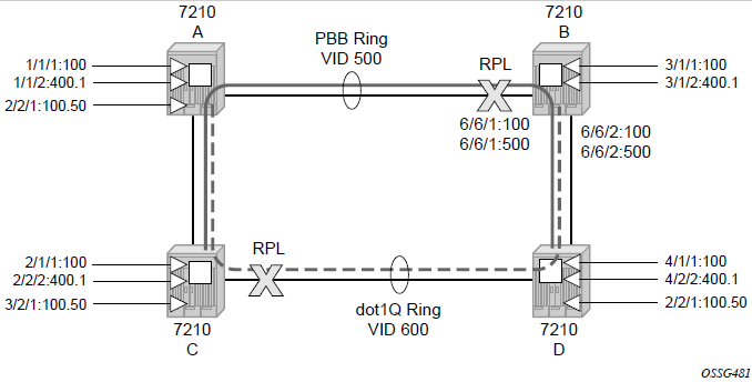
The following diagram shows an example G.8032 ring. The following Figure: 0 to 3 ring example shows a resilient ring service. In the ring example, a QinQ ring (solid line) using VID 500 carries two customer VLANs dot1q 100 and QinQ 400.1, respectively). The RPL for the G.8032 ring is between A and B, where B is the RPL owner. Figure: 0 to 3 ring example is also a QinQ service on the (dotted line) ring that uses dot1q VID 600 for the ring to connect service VLAN 100.50.
The two rings have RPLs on different nodes which allow a form of load balancing. The example serves to illustrate that service encapsulations and ring encapsulation can be mixed in various combinations.
Neither of the rings is a closed loop. A ring can restore connectivity when any one node or link fails to all remaining nodes within a small amount of transfer time (signaling time after detection).

The following is a sample configuration output for G.8032 ring for the preceding figure.
Step #1 - Configure G.8032 ring Paths and Control MEPs used for failure detection on ring ports.
Sample configuration:
configure eth-ring 1
     description "Ring PBB BLUE on Node B"
     revert-time 100
     guard-time 5
     ccm-hold-time down 100 up 200
     rpl-node owner
     path a 1/1/1 raps-tag 100 // CC Tag 100
          description "To A ring link"
          rpl-end
          eth-cfm
               mep 1 domain 1 association 1 direction down  // Control MEP
                    no shutdown
               ccm-enable
               control-mep
               exit
          exit
          no shutdown  // would allow protect switching
                // in absence of the "force" cmd
     exit
     path b 6/6/2 raps-tag 100 //Tag 100
          description "to D Ring Link"
          eth-cfm
               mep 1 domain 1 association 1 direction down
                    no shutdown
                         ccm-enable
                         control-mep
               exit
          exit
          no shutdown
     exit
no shutdown
exit
Step #2 - Configure VPLS service used for G.8032 control instances (identified with VID tag 100 and 500) used to exchange R-APS messages for the two control instances created on the ring.
configure> service
     vpls 10 customer 1 create // Ring APS SAPs
          description "Ring Control VID 100"
          sap 1/1/1:100 eth-ring 1 create  // TAG for the Control Path a
          exit
          sap 6/6/2:100 eth-ring 1 create  // TAG for the Control Path b
          exit
          no shutdown
     exit
configure> service
     vpls 40 customer 1 create //Data Channel on Ring
          description "Ethernet Ring 1 VID 500"
          sap 1/1/1:500 eth-ring 1 create   // TAG for the Data Channel Path a
          exit
          sap 6/6/2:500 eth-ring 1 create   // TAG for the Data Channel Path b
          exit
     exit
Step #3 - Configure VPLS data services that will use G.8032 for protection.
configure> service vpls 1001 // CPE traffic
          sap 3/1/2:400.1 create
          // CPE SAP
          exit

          sap 6/6/1:2000 create
          // uplink SAP
          exit

          no shutdown
     exit

configure> service vpls 1001 // CPE traffic
          sap 2/2/1:100.50 create
          // CPE SAP
          exit

          sap 6/6/1:600 create
          // uplink SAP
          exit

          no shutdown
     exit