The remote LFA next-hop calculation by the IGP LFA SPF is enabled by appending the remote-lfa option to the loopfree-alternate command:
configure>router>isis>loopfree-alternate remote-lfa
    configure>router>ospf>loopfree-alternate remote-lfa
The SPF calculates the remote LFA after the regular LFA next-hop calculation when the following conditions are met:
The remote-lfa option is enabled in an IGP instance.
The LFA next-hop calculation did not result in protection for one or more prefixes resolved to a specific interface.
Remote LFA extends the loop-free alternate fast reroute (LFA FRR) protection coverage to any topology by automatically computing and establishing or tearing down shortcut tunnels (repair tunnels) to a remote LFA node that puts the packets back on the shortest path without looping them back to the node that forwarded them over the repair tunnel. A repair tunnel can be an RSVP LSP, an LDP-in-LDP tunnel, or an SR tunnel. This feature is restricted to using an SR repair tunnel to the remote LFA node.
The remote LFA feature can only use an SR repair tunnel to the remote LFA node.
The remote LFA algorithm for link protection is described in RFC 7490, Remote Loop-Free Alternate (LFA) Fast Reroute (FRR). Unlike the regular LFA calculation, which is calculated per prefix, the LFA algorithm for link protection is a per-link LFA SPF calculation. It provides protection for all destination prefixes that share the protected link by using the neighbor on the other side of the protected link as a proxy for all destinations. The following figure shows an example of a remote LFA topology.
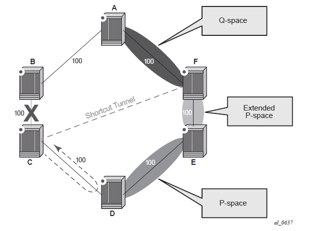
When the LFA SPF in node C computes the per-prefix LFA next-hop, prefixes that use link C to B as the primary next-hop have no LFA next-hop because of the ring topology. If node C uses node link C to D as a back-up next-hop, node D loops a packet back to node C. The remote LFA then runs the ‟PQ Algorithm” as described in RFC 7490.
Computes the extended P space of node C for link C to B. The extended P space is the set of nodes reachable from node C without any path transiting the protected link (C to B). The computation yields nodes D, E, and F.
The extended P space of node C is determined by running SPF on behalf of each of the neighbors of C; the same computation is used for the regular LFA.
Note:According to the P space concept initially introduced in RFC 7490, node F would be excluded from the P space because, from the node C perspective, a few node C has a couple of ECMP paths would already exist in node C, including a path going through link C to B. However, because the remote LFA next-hop is activated when link C-B fails, this rule can be relaxed to include node F, which then yields the extended P space.
You can limit the search for candidate P nodes to reduce the number of SPF calculations in topologies where many eligible P nodes may exist. Use the following CLI commands to configure the maximum IGP cost from node C for a P node to be an eligible candidate:
configure>router>isis>loopfree-alternate remote-lfa max-pq-cost value
configure>router>ospf>loopfree-alternate remote-lfa max-pq-cost value
Compute the Q space of node B for link C-B. The Q space is the set of nodes from which the destination proxy (node B) can be reached without a path transiting the protected link (link C-B).
The Q space calculation is a reverse SPF on node B. A reverse SPF is run on behalf of each neighbor of C to protect all destinations that resolve over the link to the neighbor. This yields nodes F and A in the example shown in Figure: Example topology remote LFA algorithm.
You can limit the search for candidate Q nodes to reduce the number of SPF calculations in topologies where many eligible Q nodes may exist. Use the CLI commands described in step1 to configure the maximum IGP cost from node C for a Q node to be an eligible candidate.
Select the best alternate node, which is the intersection of extended P and Q spaces. In the Figure: Example topology remote LFA algorithm example, the best alternate node (PQ node) is node F. From node F onwards, traffic follows the IGP shortest path.
If many PQ nodes exist, the lowest IGP cost from node C is used to narrow the selection; if more than one PQ node remains, the node with the lowest router ID is selected.
The following figure shows label stack encoding for a packet that is forwarded over the remote LFA next-hop.
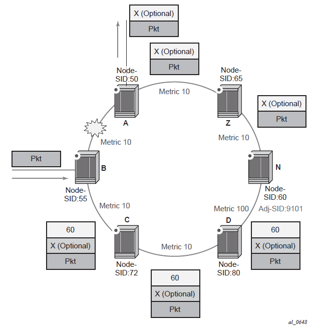
The label corresponding to the node SID of the PQ node is pushed on top of the original label of the SID of the resolved destination prefix. If node C has resolved multiple node SIDs corresponding to different prefixes of the selected PQ node, it pushes the lowest node SID label on the packet when forwarded over the remote LFA backup next-hop.
If the PQ node is also the advertising router for the resolved prefix, the label stack is compressed in the following cases depending on the IGP:
In IS-IS, the label stack is always reduced to a single label, which is the label of the resolved prefix owned by the PQ node.
In OSPF, the label stack is reduced to the single label of the resolved prefix when the PQ node advertises a single node SID in this OSPF instance. If the PQ node advertises a node SID for multiple of its loopback interfaces within the same OSPF instance, the label stack is reduced to a single label only in the case where the SID of the resolved prefix is the lowest SID value.
The following rules and limitations apply to the remote LFA implementation:
LFA policy is supported for IP next-hops only. It is not supported with tunnel next-hops when IGP shortcuts are used for LFA backup. Remote LFA is also a tunnel next-hop and a user-configured LFA policy is not applied in the selection of a remote LFA backup next-hop when multiple candidates are available.
As a result, if an LFA policy is applied and does not find an LFA IP next-hop for a set of prefixes, the remote LFA SPF searches for a remote LFA next-hop for the same prefixes. The selected remote LFA next-hops, if found, may not satisfy the LFA policy constraints.
If the loopfree-alternate-exclude CLI command (IS-IS or OSPF context of the interface) is used to exclude a network IP interface from being used as an LFA next-hop, the interface is also excluded from being used as the outgoing interface for a remote LFA tunnel next-hop.
As with the regular LFA algorithm, the remote LFA algorithm computes a backup next-hop to the ABR advertising an inter-area prefix and not to the destination prefix.