LDP over RSVP-TE provides end-to-end tunnels that have two important properties, fast reroute and traffic engineering which are not available in LDP. LDP over RSVP-TE is focused at large networks (over 100 nodes in the network). Simply using end-to-end RSVP-TE tunnels will not scale. While an LER may not have that many tunnels, any transit node will potentially have thousands of LSPs, and if each transit node also has to deal with detours or bypass tunnels, this number can make the LSR overly burdened.
Use of the implicit NULL MPLS label must be enabled with use of LDPoRSVP. Use the command configure>router>rsvp>implicit-null-label and configure>router>ldp> implicit-null-label to enable use of implicit NULL MPLS labels.
Only FRR one-to-one is supported when LDPoRSVP is used. FRR facility is not supported. This is not blocked in the CLI, but operators need to ensure it when configuring the nodes.
LDP over RSVP-TE allows tunneling of user packets using an LDP LSP inside an RSVP LSP.The main application of this feature is for deployment of MPLS based services, for example, VPRN, VLL, and VPLS services, in large scale networks across multiple IGP areas without requiring full mesh of RSVP LSPs between PE routers.
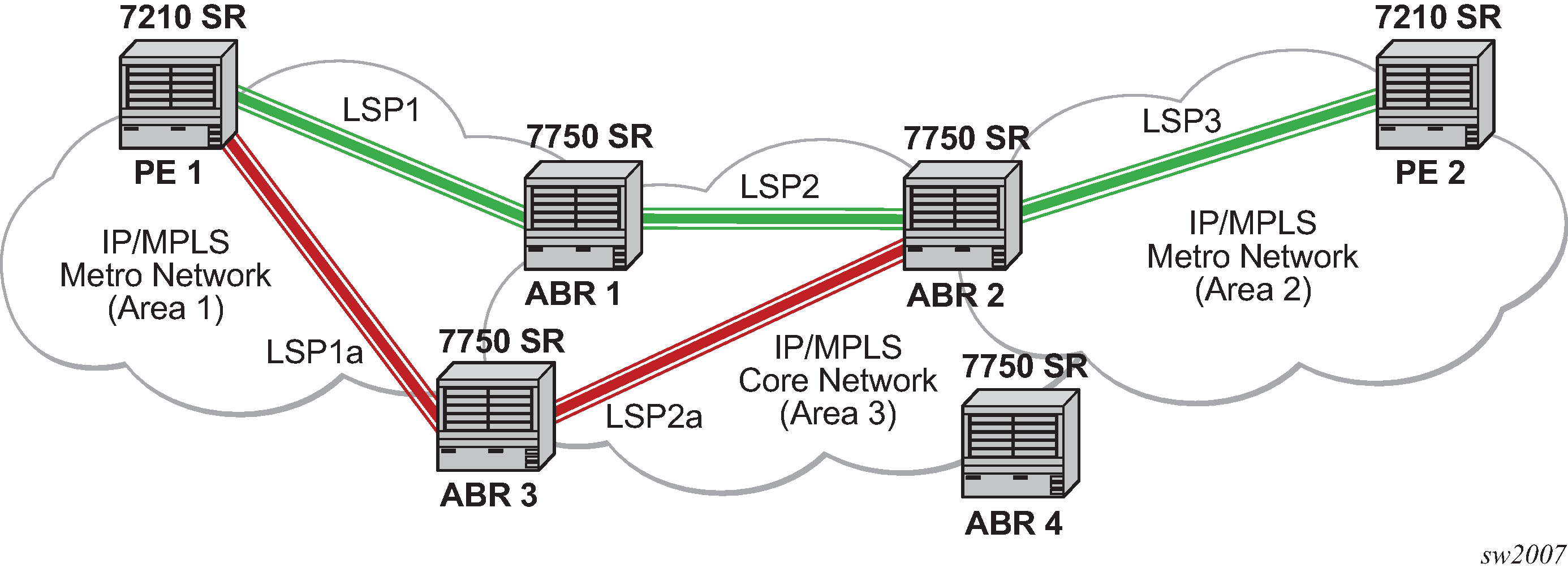
The network displayed in Figure: LDP over RSVP application consists of two metro areas, Area 1 and 2 respectively, and a core area, Area 3. Each area makes use of TE LSPs to provide connectivity between the edge routers. To enable services between PE1 and PE2 across the three areas, LSP1, LSP2, and LSP3 are set up using RSVP-TE. There are in fact 6 LSPs required for bidirectional operation but we will refer to each bidirectional LSP with a single name, for example, LSP1. A targeted LDP (T-LDP) session is associated with each of these bidirectional LSP tunnels. That is, a T-LDP adjacency is created between PE1 and ABR1 and is associated with LSP1 at each end. The same is done for the LSP tunnel between ABR1 and ABR2, and finally between ABR2 and PE2. The loopback address of each of these routers is advertised using T-LDP. Similarly, backup bidirectional LDP over RSVP tunnels, LSP1a and LSP2a, are configured via ABR3.

This setup effectively creates an end-to-end LDP connectivity which can be used by all PEs to provision services. The RSVP LSPs are used as a transport vehicle to carry the LDP packets from one area to another. Note that only the user packets are tunneled over the RSVP LSPs. The T-LDP control messages are still sent unlabeled using the IGP shortest path.
In this application, the bidirectional RSVP LSP tunnels are not treated as IP interfaces and are not advertised back into the IGP. A PE must always rely on the IGP to look up the next hop for a service packet. LDP-over-RSVP introduces a new tunnel type, tunnel-in-tunnel, in addition to the existing LDP tunnel and RSVP tunnel types. If multiple tunnels types match the destination PE FEC lookup, LDP will prefer an LDP tunnel over an LDP-over-RSVP tunnel by default.
The design in Figure: LDP over RSVP application allows a service provider to build and expand each area independently without requiring a full mesh of RSVP LSPs between PEs across the three areas.
To participate in a VPRN service, PE1 and PE2 perform the autobind to LDP. The LDP label which represents the target PE loopback address is used below the RSVP LSP label. Therefore a 3 label stack is required.
To provide a VLL service, PE1 and PE2 are still required to set up a targeted LDP session directly between them. Again a 3 label stack is required, the RSVP LSP label, followed by the LDP label for the loopback address of the destination PE, and finally the pseudowire label (VC label).
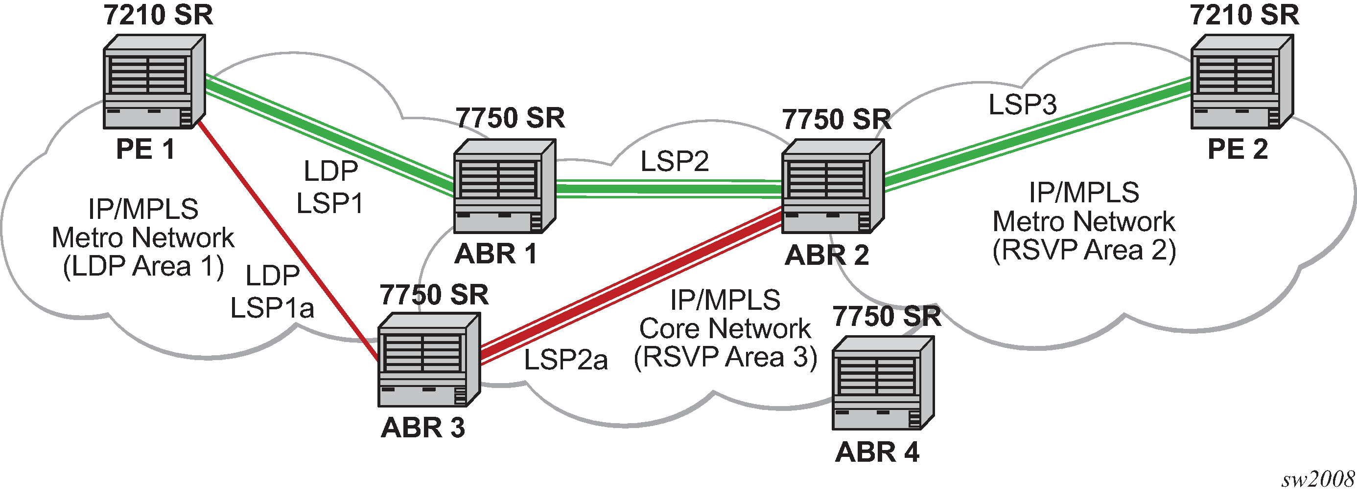
This implementation supports a variation of the application in Figure: LDP over RSVP application, in which area 1 is an LDP area. In that case, PE1 will push a two label stack while ABR1 will swap the LDP label and push the RSVP label as shown in Figure: LDP over RSVP application variant.
