VCCV effectively creates an IP control channel within the pseudowire between PE1 and PE2. PE2 should be able to distinguish on the receive side VCCV control messages from user packets on that VLL. There are three possible methods of encapsulating a VCCV message in a VLL which translates into three types of control channels:
Use of a Router Alert Label immediately preceding the VC label. This method has the drawback that if ECMP is applied to the outer LSP label (for example, transport label), the VCCV message will not follow the same path as the user packets. This effectively means it will not troubleshoot the appropriate path. This method is supported by the 7210 SAS.
Use of the OAM control word as illustrated in the following figure.
Figure: OAM control word format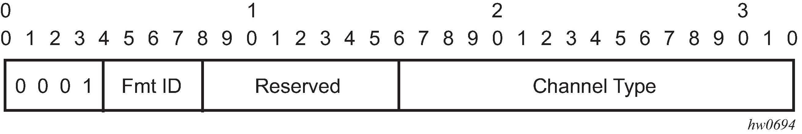
The first nibble is set to 0x1. The Format ID and the reserved fields are set to 0 and the channel type is the code point associated with the VCCV IP control channel as specified in the PWE3 IANA registry (RFC 4446). The channel type value of 0x21 indicates that the Associated Channel carries an IPv4 packet.
The use of the OAM control word assumes that the draft-martini control word is also used on the user packets. This means that if the control word is optional for a VLL and is not configured, the PE node will only advertise the router alert label as the CC capability in the Label Mapping message. This method is supported on 7210 SAS configured in the network mode of operation.
Set the TTL in the VC label to 1 to force PE2 control plane to process the VCCV message. This method is not guaranteed to work under all circumstances. For instance, the draft mentions some implementations of penultimate hop popping overwrite the TTL field. This method is not supported on the 7210 SAS.
When sending the label mapping message for the VLL, PE1 and PE2 must indicate which of the preceding OAM packet encapsulation methods (for example, which control channel type) they support. This is accomplished by including an optional VCCV TLV in the pseudowire FEC Interface Parameter field. The following figure shows the format of the VCCV TLV.
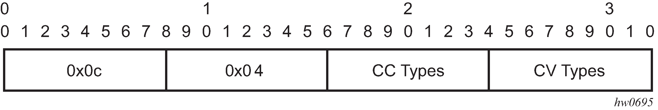
Note that the absence of the optional VCCV TLV in the Interface parameters field of the pseudowire FEC indicates the PE has no VCCV capability.
The Control Channel (CC) Type field is a bitmask used to indicate if the PE supports none, one, or many control channel types, as follows:
0x00 None of the following VCCV control channel types are supported
0x01 PWE3 OAM control word (see Figure: OAM control word format)
0x02 MPLS Router Alert Label
0x04 MPLS inner label TTL = 1
If both PE nodes support more than one of the CC types, a 7210 SAS PE will make use of the one with the lowest type value. For instance, OAM control word will be used in preference to the MPLS router alert label.
The Connectivity Verification (CV) bitmask field is used to indicate the specific type of VCCV packets to be sent over the VCCV control channel. The valid values are:
0x00 None of the following VCCV packet type are supported.
0x01 ICMP ping. Not applicable to a VLL over a MPLS SDP and therefore is not supported by the 7210 SAS.
0x02 LSP ping. This is used in VCCV-Ping application and applies to a VLL over an MPLS SDP. This is supported by the 7210 SAS.
A VCCV ping is an LSP echo request message as defined in RFC 4379. It contains an L2 FEC stack TLV which must include within the sub-TLV type 10 ‟FEC 128 Pseudowire”. It also contains a field which indicates to the destination PE which reply mode to use. There are four reply modes defined in RFC 4379:
Reply mode, meaning:
Do not reply. This mode is supported by the 7210 SAS.
Reply via an IPv4/IPv6 UDP packet. This mode is supported by the 7210 SAS.
Reply with an IPv4/IPv6 UDP packet with a router alert. This mode sets the router alert bit in the IP header and is not be confused with the CC type which makes use of the router alert label. This mode is not supported by the 7210 SAS.
Reply via application level control channel. This mode sends the reply message in-band over the pseudowire from PE2 to PE1. PE2 will encapsulate the Echo Reply message using the CC type negotiated with PE1. This mode is supported by the 7210 SAS.
The reply is an LSP echo reply message as defined in RFC 4379. The message is sent as per the reply mode requested by PE1. The return codes supported are the same as those supported in the 7210 SAS LSP ping capability.
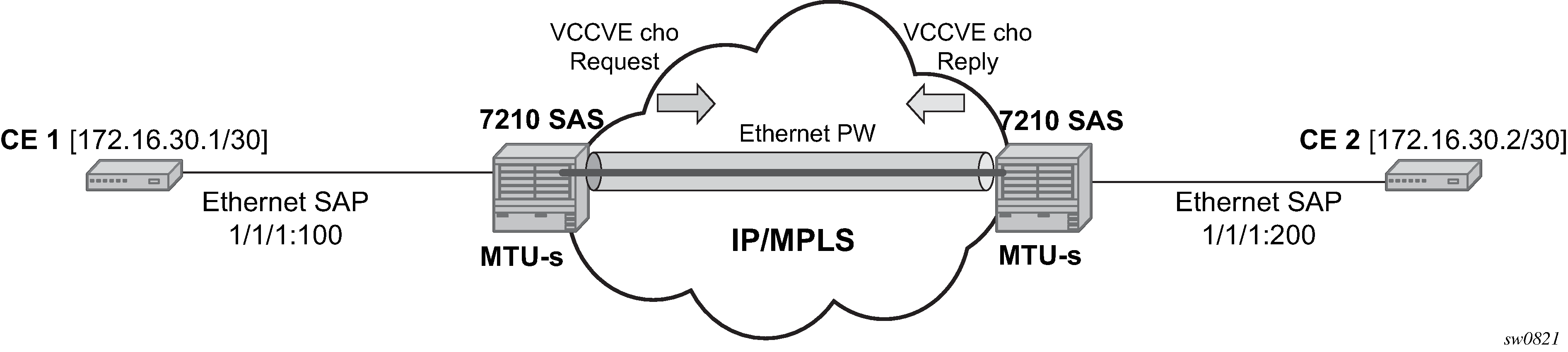
The VCCV ping feature is in addition to the service ping OAM feature which can be used to test a service between 7210 SAS nodes. The VCCV ping feature can test connectivity of a VLL with any third party node which is compliant to RFC 5085.
The following figure shows the VCCV-ping feature application.