3.17. Configuring MPLS and RSVP-TE with CLI
This section provides information to configure MPLS and RSVP-TE using the CLI.
Topics in this section include:
3.18. MPLS Configuration Overview
MPLS enables routers to forward traffic based on a label embedded in the packet header. A router examines the label to determine the next hop for the packet, instead of router address lookups to the next node when forwarding packets.
To implement MPLS on an LSP for outer tunnel and pseudowire assignment, the following entities must be configured:
- Signaling Protocol (for RSVP-TE or LDP)
3.18.1. Router Interface
At least one router interface and one system interface must be defined in the config>router>interface context in order to configure MPLS on an interface.
3.18.1.1. E-LSP for Differentiated Services
An EXP-inferred LSP (E-LSP) is an LSP that can support a variety of VLLs or traffic types. Up to eight types of traffic can be multiplexed over an E-LSP.
The prioritization of mission-critical traffic is handled by the settings of the three EXP bits. The EXP bits designate the importance of a particular packet. The classification and queuing at the Provider (P) or Provider Edge (PE) nodes typically take place based on the value of the EXP bits. Refer to the 7705 SAR Quality of Service Guide for more information on the use of EXP bits and differentiated services on the 7705 SAR.
3.18.2. Paths
To configure signaled LSPs, you must first create one or more named paths on the ingress router using the config>router>mpls>path command. For each path, the transit routers (hops) in the path are specified.
3.18.3. LSPs
The 7705 SAR supports static and dynamic LSPs.
To configure MPLS-signaled (dynamic) LSPs, the LSP must run from an ingress LER to an egress LER. Configure the dynamic LSP only at the ingress router, and either configure the LSP to allow the router software to make the forwarding decisions or configure some or all routers in the LSP path statically. The LSP is set up by RSVP-TE signaling messages. The 7705 SAR automatically manages label values. Labels that are automatically assigned have values ranging from 1024 through 1 048 575 (see Label Values).
A static LSP is a manually configured LSP where the next hop IP address and the outgoing label are explicitly specified.
To establish a static LSP, an LSP must be configured from an ingress LER to an egress LER. Labels must be manually assigned and the label values must be within the range of 32 to 1023 (see Label Values).
3.18.4. Pseudowires
To configure PW/VLL labels, the PW/VLL service must be configured. PW/VLL labels can be configured manually as statically allocated labels using any unused label within the static label range. Pseudowire/VLL labels can also be dynamically assigned by targeted LDP. Statically allocated labels and dynamically allocated labels are designated differently in the label information base.
PW/VLL labels are uniquely identified against a 7705 SAR, not against an interface or module.
As defined in RFC 3036, LDP Specification, and RFC 4447 Pseudowire Setup and Maintenance Using the Label Distribution Protocol (LDP), label distribution is handled in the Downstream Unsolicited (DU) mode. Generic Label TLV is used for all setup and maintenance operations.
3.18.5. Signaling Protocol
For static LSPs, the path and the label mappings and actions configured at each hop must be specified manually. RSVP-TE or LDP is not required for static LSPs.
For dynamic LSPs, RSVP-TE or LDP must be turned on. See RSVP and RSVP-TE or Label Distribution Protocol.
To implement dynamic pseudowire/VLL labels, entities must be enabled as follows:
- MPLS must be enabled on all routers that are part of a static LSP
- LDP must be enabled on the ingress and egress LERs
When MPLS is enabled and either RSVP-TE or LDP is also enabled, MPLS uses RSVP-TE or LDP to set up the configured LSPs. For example, when you configure an LSP with both MPLS and RSVP-TE running, RSVP-TE initiates a session to create the LSP. RSVP-TE uses the local router as the RSVP-TE session sender and the LSP destination as the RSVP-TE session receiver. Once the RSVP-TE session is created, the LSP is set up on the path created by the session. If the session is not successfully created, RSVP-TE notifies MPLS; MPLS can then either initiate backup paths or retry the initial path.
3.19. Basic MPLS Configuration
This section provides information to configure MPLS and gives configuration examples of common configuration tasks. To enable MPLS on a 7705 SAR router, you must configure at least one MPLS interface. The MPLS interface is configured in the config>router> mpls context. The other MPLS configuration parameters are optional.
The following example displays an MPLS configuration output. The admin-group is configured in the config>router>if-attribute context and associated with the MPLS interface in the config>router>mpls>interface context.
3.20. Common Configuration Tasks
This section provides a brief overview of the tasks to configure MPLS and provides the CLI commands.
The following protocols must be enabled on each participating router:
- MPLS
- RSVP-TE (for RSVP-TE-signaled MPLS only)
- LDP
In order for MPLS to run, you must configure at least one MPLS interface in the config>router>mpls context.
- An interface must be created in the config>router>interface context before it can be applied to MPLS.
- In the config>router>mpls context, configure the path parameters. A path specifies some or all hops from ingress to egress. A path can be used by multiple LSPs.
- When an LSP is created, the egress router must be specified in the to command and at least one primary or secondary path must be specified. All other settings under the LSP hierarchy are optional.
3.20.1. Configuring MPLS Components
Use the MPLS and RSVP-TE CLI syntax shown in the following information for:
3.20.2. Configuring Global MPLS Parameters
Admin groups can signify link colors, such as red, yellow, or green, or some other link quality. Shared risk link groups (SRLGs) are lists of interfaces that share the same risk of failure due to shared resources. MPLS interfaces advertise the admin groups and SRLGs that they support. CSPF uses the information when paths are computed for constraint-based LSPs. CSPF must be enabled in order for admin groups and SRLGs to be relevant.
Admin groups and SRLGs are created in the config>router>if-attribute context. Other global parameters are created in the config>router>mpls context.
To configure global MPLS parameters, enter the following commands:
The following example displays a global MPLS configuration output.
3.20.3. Configuring an MPLS Interface
The interface must exist in the system before it can be configured as an MPLS interface; refer to the 7705 SAR Router Configuration Guide for more information.
Once the MPLS protocol instance is created, the no shutdown command is not required since MPLS is administratively enabled upon creation. Configure the label-map parameters if the interface is used in a static LSP.
Use the following CLI syntax to configure an MPLS interface on a router:
The following example displays the interface configuration output.
3.20.4. Configuring MPLS Paths
When configuring an MPLS path for LSPs, the IP address of each hop that the LSP should traverse on its way to the egress router must be specified. The intermediate hops must be configured as either strict or loose, meaning that the LSP must take either a direct path from the previous hop router to this router (strict) or can traverse other routers (loose).
Use the following CLI syntax to configure a path:
The following example displays a path configuration output.
3.20.5. Configuring an MPLS LSP
When configuring an LSP, you must specify the IP address of the egress router in the to statement. You must also specify the primary path to be used. Secondary paths can be explicitly configured or signaled upon the failure of the primary path. All other statements are optional.
The following displays an MPLS LSP configuration.
3.20.6. Configuring a Static LSP
An LSP can be explicitly (manually) configured. The reserved range of static LSP labels is 32 to 1023. Static LSPs are configured on every node along the LSP path. The label’s forwarding information includes the address of the next hop router.
Use the following CLI syntax to configure a static LSP:
The following example displays the static LSP configuration output.
3.20.6.1. Configuring a Fast-Retry Timer for Static LSPs
A fast-retry timer can be configured for static LSPs. When a static LSP is trying to come up, MPLS tries to resolve the ARP entry for the next hop of the LSP. This request may fail because the next hop might still be down or unavailable. In that case, MPLS starts a retry timer before making the next request. The fast-retry command allows the user to configure the retry timer so that the LSP comes up shortly after the next hop is available.
Use the following CLI syntax to configure a fast-retry timer for static LSPs:
3.20.7. Configuring Manual Bypass Tunnels
Consider the following network setup in Figure 15. Assume that a manual bypass tunnel must be configured on Node B.
Figure 15: Manual Bypass Tunnels
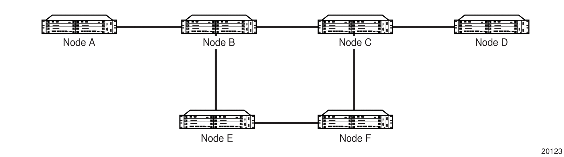
- Disable dynamic bypass tunnels on Node B.The CLI syntax for this configuration is:config>router>mpls>dynamic-bypass [disable | enable]By default, dynamic bypass tunnels are enabled.
- Configure an LSP on Node B, such as B-E-F-C, which will be used only as a bypass. Specify each hop in the path and assign its strict or loose option; in this case, the bypass LSP will have a strict path. Designate the LSP as a primary LSP.The CLI syntax for this configuration is:config>router>mpls>path path-name>hop hop-index ip-address [strict | loose]config>router>mpls>lsp lsp-name bypass-only(see also the configuration example below)Including the bypass-only keyword disables some options under the LSP configuration. See Table 8.
Table 8: Disabled and Enabled Options for Bypass-Only
Disabled Options
Enabled Options
- bandwidth
- fast-reroute
- secondary
- adaptive
- adspec
- cspf
- exclude
- hop-limit
- include
- metric
- Configure an LSP from A to D and indicate fast-reroute bypass protection by selecting facility as the FRR method.The CLI syntax for this configuration is:config>router>mpls>lsp lsp-name>fast-reroute facilityIf the LSP from A to D goes through Node B and bypass is requested, the next hop is Node C, and there is a manually configured bypass-only tunnel from B to C that excludes link BC (that is, path BEFC), then Node B uses the bypass-only tunnel.
The following example displays a bypass tunnel configuration output.
3.20.8. Configuring RSVP-TE Parameters and Interfaces
RSVP-TE is used to set up LSPs. RSVP-TE must be enabled on the router interfaces that are participating in signaled LSPs. The default values can be modified in the config>router>rsvp context.
Initially, interfaces are configured in the config>router>mpls>interface context. Only these existing (MPLS) interfaces are available to be modified in the config>router>rsvp context. Interfaces cannot be directly added in the rsvp context.
The following example displays an RSVP-TE configuration output.
3.20.9. Configuring RSVP-TE Message Pacing Parameters
RSVP-TE message pacing maintains a count of the messages that were dropped because the output queue for the egress interface was full.
Use the following CLI syntax to configure RSVP-TE message pacing parameters:
The following example displays an RSVP-TE message pacing configuration output.
3.21. MPLS Configuration Management Tasks
This section discusses the following MPLS configuration management tasks:
3.21.1. Deleting MPLS
The no form of the mpls command typically removes an MPLS instance and all associated information. However, MPLS must be disabled (shut down) and all SDP bindings to LSPs removed before an MPLS instance can be deleted. Once MPLS is shut down, the no mpls command deletes the protocol instance and removes all configuration parameters for the MPLS instance.
If MPLS is not shut down first, when the no mpls command is executed, a warning message on the console indicates that MPLS is still administratively up.
To delete the MPLS instance:
- Disable the MPLS instance using the shutdown command.
- Remove the MPLS instance from the router using the no mpls command.
3.21.2. Modifying MPLS Parameters
| Note: You must shut down MPLS entities in order to modify parameters. Re-enable (no shutdown) the entity for the change to take effect. |
3.21.3. Modifying an MPLS LSP
Some MPLS LSP parameters (such as primary and secondary), must be shut down before they can be edited or deleted from the configuration.
The following example displays an MPLS LSP configuration output. Refer to Configuring an MPLS Interface.
3.21.4. Modifying MPLS Path Parameters
In order to modify path parameters, the config>router>mpls>path context must be shut down first.
The following example displays an MPLS path configuration output. Refer to Configuring MPLS Paths.
3.21.5. Modifying MPLS Static LSP Parameters
Use the show>service>router>static-lsp command to display a list of LSPs.
In order to modify static LSP parameters, the config>router>mpls>static-lsp lsp-name context must be shut down.
To modify an LSP:
- Access the specific LSP by specifying the LSP name, and then shut it down.
- Enter the parameter to modify and then enter the new information.
The following example displays the static LSP configuration output.
3.21.6. Deleting an MPLS Interface
To delete an interface from the MPLS configuration:
- Administratively disable the interface using the shutdown command.
- Delete the interface with the no interface command.
The following example displays the configuration output when interface “to-104” has been deleted.
3.22. RSVP-TE Configuration Management Tasks
This section discusses the following RSVP-TE configuration management tasks:
3.22.1. Modifying RSVP-TE Parameters
Only interfaces configured in the MPLS context can be modified in the rsvp context.
The no rsvp command deletes this RSVP-TE protocol instance and removes all configuration parameters for this RSVP-TE instance. The shutdown command suspends the execution and maintains the existing configuration.
The following example displays a modified RSVP-TE configuration output.
3.22.2. Modifying RSVP-TE Message Pacing Parameters
RSVP-TE message pacing maintains a count of the messages that were dropped because the output queue for the egress interface was full.
The following example displays a modified RSVP-TE message pacing configuration output. Refer to Configuring RSVP-TE Message Pacing Parameters.
3.22.3. Deleting an Interface from RSVP-TE
Interfaces cannot be deleted directly from the RSVP-TE configuration. Because an interface is created in the mpls context and then configured in the rsvp context, it can only be deleted in the mpls context This removes the association from RSVP-TE.
Refer to Deleting an MPLS Interface.
3.23. Configuring and Operating SR-TE
This section provides information on the configuration and operation of the Segment Routing with Traffic Engineering (SR-TE) LSP. It covers the following topics:
3.23.1. SR-TE Configuration Prerequisites
To configure SR-TE, the user must first configure the prerequisite parameters.
First, configure the label space partition for the Segment Routing Global Block (SRGB) for all participating routers in the segment routing domain by using the mpls-labels>sr-labels command.
Enable segment routing, traffic engineering, and advertisement of router capability in all participating IGP instances in all participating routers by using the traffic-engineering, advertise-router-capability, and segment-routing commands.
Configure a segment routing tunnel MTU for the IGP instance, if required, by using the tunnel-mtu command.
Assign a node SID to each loopback interface that a router would use as the destination of a segment routing tunnel by using the node-sid command.
3.23.2. SR-TE LSP Configuration Overview
An SR-TE LSP can be configured as an LSP using the existing CLI command hierarchy under the MPLS context and specifying the sr-te LSP type.
A primary path can be configured for the SR-TE LSP.
Use the following CLI syntax to associate an empty path or a path with strict or loose explicit hops with the primary paths of the SR-TE LSP:
3.23.3. Configuring Path Computation and Control for SR-TE LSPs
Use the following syntax to configure the path computation requests only (PCE-computed) or both path computation requests and path updates (PCE-controlled) to the PCE for a specific LSP:
The PCC LSP database is synchronized with the PCE LSP database using the PCEP PCRpt (PCE Report) message for LSPs that have the following commands enabled:
3.23.3.1. Configuring Path Profile and Group for PCC-initiated and PCE-computed/controlled LSPs
The PCE supports the computation of disjoint paths for two different LSPs originating or terminating on the same or different PE routers. To indicate this constraint to the PCE, the user must configure the PCE path profile ID and path group ID that the LSP belongs to. These parameters are passed transparently by the PCC to the PCE and are therefore opaque data to the router. Use the following syntax to configure the path profile and path group:
The association of the optional path group ID is to allow the PCE to determine which profile ID this path group ID must be used with. One path group ID is allowed per profile ID. The user can, however, enter the same path group ID with multiple profile IDs by executing this command multiple times. A maximum of five entries of path-profile [path-group] can be associated with the same LSP. More details of the operation of the PCE path profile are provided in the PCEP chapter.
3.23.4. Configuring SR-TE LSP Label Stack Size
Use the following syntax to configure the maximum number of labels that the ingress LER can push for a specific SR-TE LSP:
This command allows the user to reduce the SR-TE LSP label stack size by accounting for additional transport (including entropy), service, and other labels when packets are forwarded in a particular context. See Data Path Support for more information about label stack size requirements in various forwarding contexts. If the CSPF on the PCE or the router's hop-to-label translation cannot find a path that meets the maximum SR label stack, the SR-TE LSP will remain on its current path or will remain down if it has no path. The range is 1 to 11 labels with a default value of 6.
3.23.5. Configuring Adjacency SID Parameters
Configure the adjacency hold timer for the LFA or remote LFA backup next hop of an adjacency SID.
Use the following syntax to configure the length time that LTN or ILM records of an adjacency SID are kept:
While protection is enabled globally for all node SIDs and local adjacency SIDs when the user enables the loopfree-alternate option in IS-IS or OSPF at the LER and LSR, there are applications where the user wants traffic to never divert from the strict hop computed by CSPF for an SR-TE LSP. In that case, use the following syntax to disable protection for all adjacency SIDs formed over a particular network IP interface:
3.23.6. Configuring PCC-controlled, PCE-computed, and PCE-controlled SR-TE LSPs
The following example shows the configuration of PCEP PCC parameters on LER routers that require peering with the PCE server:
The following example shows the configuration of a PCC-controlled SR-TE LSP that is not reported to the PCE:
The following example shows the configuration of a PCC-controlled SR-TE LSP that is reported to the PCE:
The following example shows the configuration of a PCE-computed SR-TE LSP that is reported to the PCE:
The following example shows the configuration of a PCE-controlled SR-TE LSP with no PCE path profile:
The following example shows the configuration of a PCE-controlled SR-TE LSP with a PCE path profile and a maximum label stack set to a non-default value: