4. OSPF
This chapter provides information about configuring the Open Shortest Path First (OSPF) protocol.
Topics in this chapter include:
4.1. Overview of OSPF
OSPF (Open Shortest Path First) is an interior gateway protocol (IGP) that is used within large autonomous systems (ASs). An autonomous system is a group of networks and network equipment under a common administration. OSPF is a link-state protocol; each router maintains an identical database (called the link-state database, topological database, or routing information database [RIB]) of the AS, including information about the local state of each router (for example, its usable interfaces and reachable neighbors).
OSPF-TE (OSPF with traffic engineering extensions) is used to advertise reachability information and traffic engineering information such as bandwidth. OSPF routers exchange status, cost, and other relevant interface information with neighboring routers. The information exchange enables all participating routers to establish their link-state database.
OSPF uses a cost metric that represents the status of the link and the bandwidth of the interface in an algorithm to determine the best route to a destination. The algorithm used is called the SPF (shortest path first) or Dijkstra algorithm. Path selection is based on lowest cost, which might not necessarily be the shortest route but is the best route in regards to bandwidth. Each router applies the algorithm to calculate the shortest path to each destination in the network.
When the best route to a particular destination is determined, the route information is sent to the routing table manager (RTM). The RTM may contain more than one best route to a destination from multiple protocols. Because metrics from different protocols are not comparable, the RTM uses preference to select the best route. The route with the lowest preference value is selected. For more information, see Configuring Route Preferences.
The best routes from the RTM are then added to the forwarding table (also known as the forwarding database [or FIB]). All forwarding decisions are based on the information in the forwarding database.
The forwarding (or dropping) of packets is controlled by filters applied to the interface and route policies applied to the OSPF protocol. Refer to the 7705 SAR Router Configuration Guide for information on filters and route policies.
The 7705 SAR implementation of OSPF conforms to OSPF Version 2 specifications presented in RFC 2328, OSPF Version 2 and OSPF Version 3 specifications presented in RFC 2740, OSPF for IPv6. Routers running OSPF can be enabled with minimal configuration. All default and command parameters can be modified.
Changes between OSPF for IPv4 and OSPFv3 for IPv6 include the following.
- Addressing semantics have been removed from OSPF packets and the basic link-state advertisements (LSAs). New LSAs have been created to carry IPv6 addresses and prefixes.
- OSPFv3 runs on a per-link basis, instead of on a per-IP-subnet basis.
- Flooding scope for LSAs has been generalized.
- Unlike OSPFv2, OSPFv3 authentication relies on IPV6's authentication header and encapsulating security payload.
- Most packets in OSPF for IPv6 are almost as compact as those in OSPF for IPv4, even with the larger IPv6 addresses.
- Most field and packet-size limitations present in OSPF for IPv4 have been relaxed.
- Option handling has been made more flexible.
The following major OSPF features are supported:
- areas – backbone, super backbone, stub, and not-so-stubby areas (NSSAs)
- virtual links
- neighbors and adjacencies
- link-state advertisements (LSAs)
- metrics
- authentication (OSPFv2 only)
- route redistribution and summarization
- OSPF traffic engineering (TE) extensions (to track and advertise available bandwidth (OSPFv2 only)– used by MPLS traffic engineering; that is, RSVP-TE)
4.1.1. OSPF Areas
An autonomous system can be divided into areas, with each area containing a group of networks. An area’s topology is concealed from the rest of the AS, which significantly reduces OSPF protocol traffic (LSA updates), simplifies the network topology, and simplifies the routing table by populating it with summarized routes rather than exact routes on each router. This decrease in LSA updates, link-state database size, and CPU time, all required for OSPF route calculations, results in a decrease in route calculation time.
All routers in an area have identical link-state databases for that area.
Areas within the same AS are linked to each other via area border routers (ABRs). An ABR is a router that belongs to, and passes reachability information between, more than one OSPF area. An ABR maintains a separate topological database for each area it is connected to.
Routing in the AS takes place on two levels, depending on whether the source and destination of a packet reside in the same area (intra-area routing) or different areas (inter-area routing). In intra-area routing, the packet is routed solely on information obtained within the area; that is, routing updates are only passed within the area. In inter-area routing, routing updates are passed between areas.
External routes refer to routing updates passed from another routing protocol into the OSPF domain.
Routers that pass information between an OSPF routing domain and a non-OSPF network are called autonomous system boundary routers (ASBRs).
4.1.1.1. Backbone Area
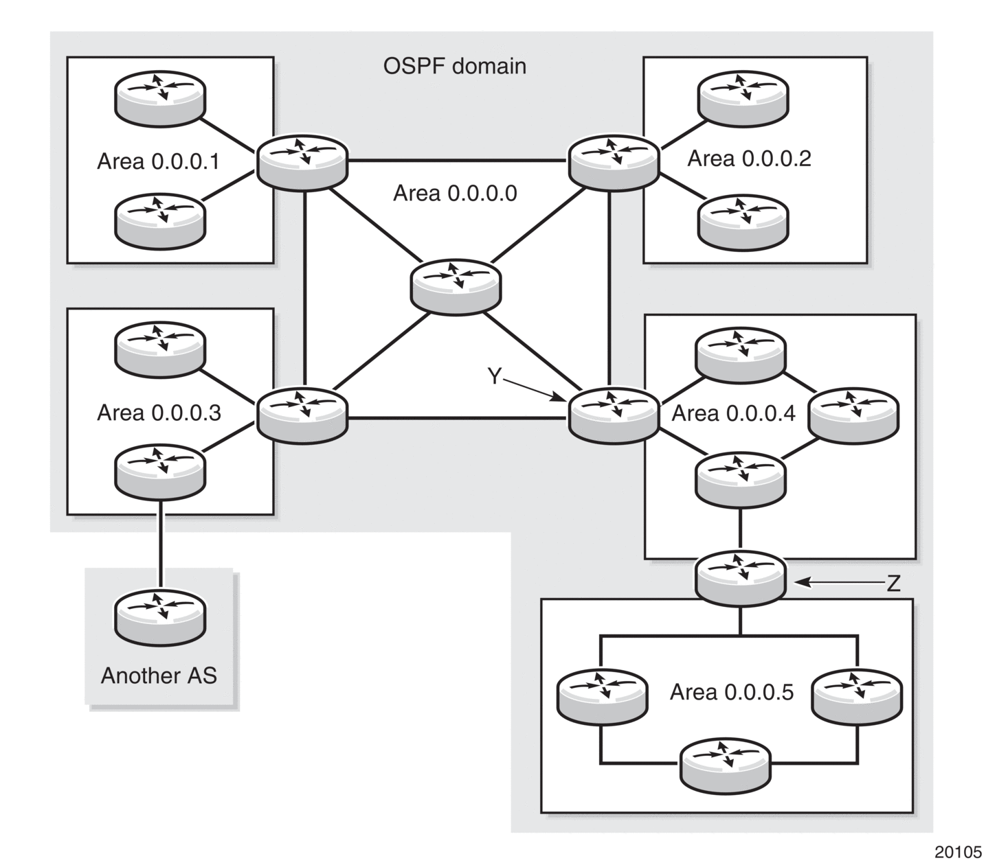
Every OSPF system requires a backbone area. The OSPF backbone area is uniquely identified as area 0 and uses the area ID 0.0.0.0. All other areas must be connected to the backbone area, either physically or logically. The backbone distributes routing information between areas. If it is not practical or possible to connect an area to the backbone (see area 0.0.0.5 in Figure 8), the ABRs (routers Y and Z in the figure) must be connected via a virtual link. The two ABRs form a point-to-point-like adjacency across the transit area (area 0.0.0.4).
Figure 8: Backbone Area
4.1.1.2. Super Backbone Area
| Note: The super backbone is only supported under the VPRN OSPF context. |
The 7705 SAR supports a version of the BGP/OSPF interaction procedures as defined in RFC 4577, OSPF as the Provider/Customer Edge Protocol for BGP/MPLS IP Virtual Private Networks (VPNs) (support for basic OSPF at PE-CE links), to provide an MPLS VPN super backbone area. The BGP/OSPF interaction procedures that are supported as part of the super backbone include the following:
- loop prevention
- handling LSAs received from the CE
- sham links
- managing VPN-IPv4 routes received by BGP
The MPLS VPN super backbone functions like an additional layer of hierarchy in OSPF. The PE routers that connect the OSPF areas to the super backbone function as OSPF ABRs in the OSPF areas to which they are attached. In order to achieve full compatibility, the PE routers can also function as ASBRs in NSSAs.
VPRN routes can be distributed among PE routers by BGP. If a PE router uses OSPF to distribute routes to a CE router, the standard procedures governing BGP/OSPF interactions cause routes from one site to be delivered to another site in type 5 LSAs as AS-external routes.
The PE routers insert inter-area routes from other areas into the area where a CE router is present. The CE routers are not involved at any level, nor are they aware of the super backbone or of other OSPF areas present beyond the MPLS VPN super backbone.
The CE always assumes that the PE is an ABR.
- If the CE is in the backbone, then the CE assumes that the PE is an ABR linking one or more areas to the backbone.
- If the CE is not in the backbone, the CE assumes that the backbone is on the other side of the PE.
- Therefore, the super backbone looks like another area to the CE.
Figure 9: PE Routers Connected to an MPLS VPN Super Backbone
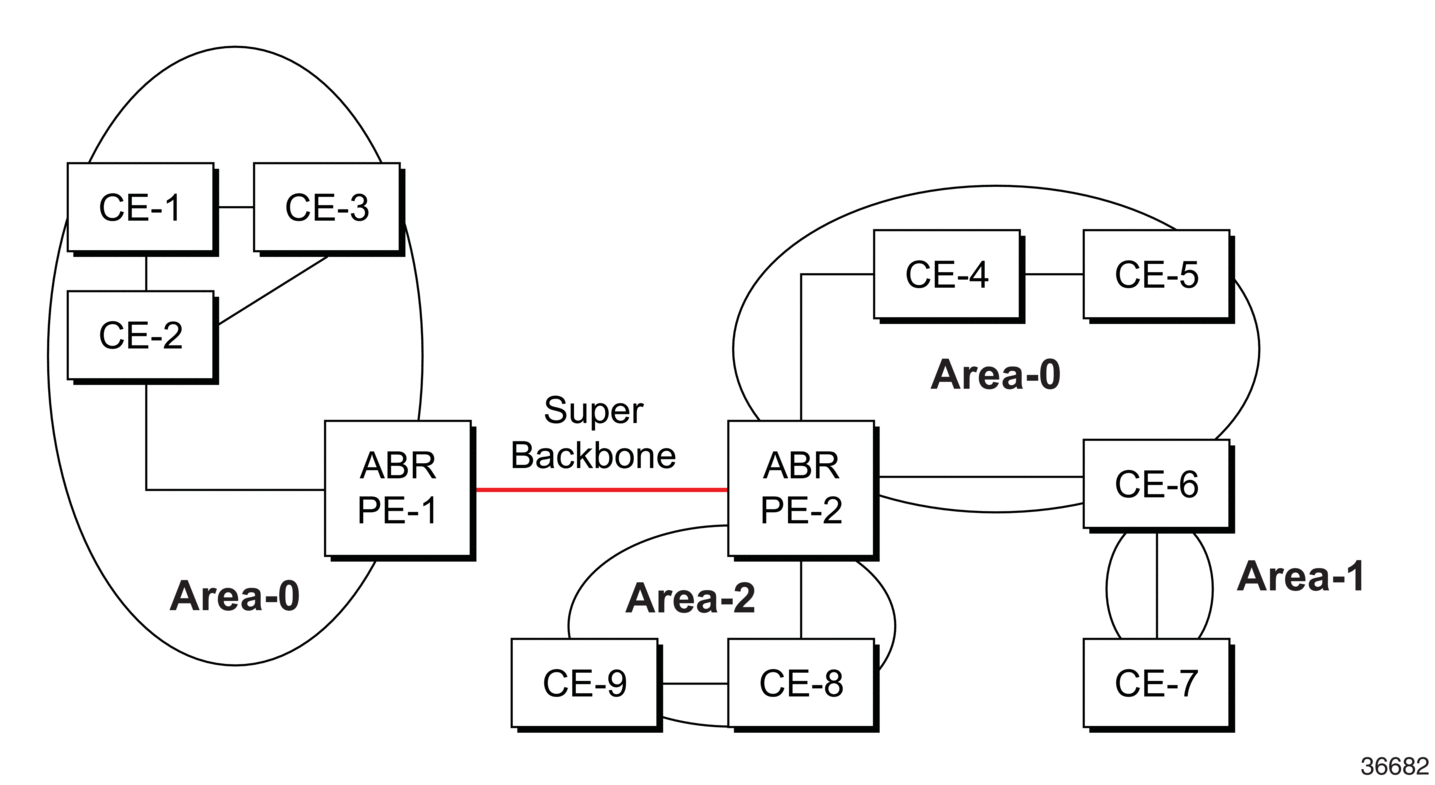
In Figure 9, the PE routers are connected to the MPLS VPN super backbone. In order to be able to distinguish if two OSPF instances are the same and require type 3 LSAs to be generated or if they are two separate routing instances that require type 5 external LSAs to be generated, the concept of a domain ID is used.
The domain ID is carried with the MP-BGP update message and indicates the source OSPF domain. When the routes are being redistributed into the same OSPF domain, the concepts of a super backbone described previously are applied and type 3 LSAs are generated. If the OSPF domain does not match the domain ID, the route type will be external.
When configuring the super backbone, all destinations learned by PEs with matching domain IDs become inter-area routes.
When configuring sham links, the links become intra-area routes if they are in the same area.
4.1.1.2.1. Sham Link
A sham link is a logical PE-to-PE unnumbered point-to-point interface that rides over the PE-to-PE transport tunnel. A sham link can be associated with any area and can appear as an intra-area link to CE routers attached to different PEs in a VPN.
Figure 10: Sham Link
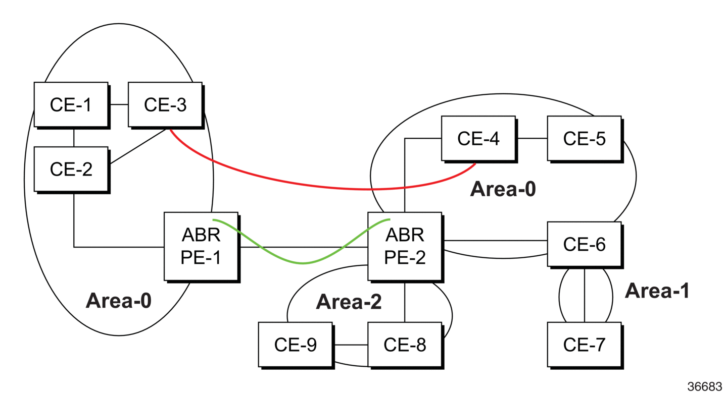
In Figure 10, the link between CE routers CE-3 and CE-4 (shown in red) is a low-speed OC-3/STM-1 link. Because the link establishes an intra-area route connection (backdoor link) between the CE-3 and CE-4 routers, a potential high-speed connection between PE routers PE-1 and PE-2 will not be utilized because OSPF always prefers intra-area links over inter-area links. Even as part of a super backbone configuration, the link between the PE routers is regarded as an inter-area connection.
To prevent the backdoor link from always being the preferred path, a sham link (shown in green) is also constructed as an inter-area link between PE routers. A normal OSPF adjacency is formed and the link-state database is exchanged across the MPLS VPN. As a result, the desired intra-area connectivity is created, and the cost of the sham link and backdoor link can be managed such that the backdoor link becomes a standby link and is used only if the sham link fails.
| Note: A sham link is only required with an MPLS VPN configuration if a backdoor link is present. |
4.1.1.2.2. Implementing the OSPF Super Backbone
With the OSPF super backbone architecture, the continuity of OSPF routing is preserved.
- The OSPF intra-area type 1 and type 2 LSAs advertised by the CE are inserted into the MPLS VPN super backbone by redistributing the OSPF route into MP-BGP by the PE adjacent to the CE.
- The MP-BGP route is propagated to other PE routers and inserted as an OSPF route into other OSPF areas. Because the PEs across the super backbone always act as ABRs, they will generate inter-area route OSPF summary type 3 LSAs.
- The inter-area route can now be propagated to other OSPF areas by other customer-owned ABRs within the customer site.
- Customer area 0 (backbone) routes appear as type 3 LSAs when carried across the MPLS VRN using MP-BGP even if the customer area remains area 0.
A BGP extended community (OSPF domain ID) provides the source domain of the route. This domain ID is not carried by OSPF but is carried by MP-BGP as an extended community attribute.
If the configured extended community value matches the receiving OSPF domain, the OSPF super backbone is implemented.
From a BGP perspective, the cost is copied into the MED attribute. For information on the MED attribute, see MED Attribute.
4.1.1.2.3. Loop Avoidance
If a route sent from a PE router to a CE router is then be received by another PE router from one of its own CE routers, routing loops may occur. RFC 4577 specifies several methods of loop avoidance.
4.1.1.2.4. DN Bit
When a type 3 LSA is sent from a PE router to a CE router, the DN bit in the LSA options field is set. This ensures that if any CE router sends the type 3 LSA to a PE router, the PE router does not redistribute it.
4.1.1.2.5. VPN Route Tag
If a particular VRF in a PE is associated with an OSPF instance, then by default the VRF is configured with a special OSPF route tag value called the VPN route tag. This route tag is included in the type 5 LSAs that the PE originates and sends to any of the attached CEs. The configuration and inclusion of the VPN route tag is required for backward compatibility with implementations that do not set the DN bit in type 5 LSAs.
4.1.1.3. Area Border Router
Areas within the same AS are linked to each other via ABRs. An ABR is a router that belongs to, and passes reachability information between, more than one area. An ABR maintains a separate topological database for each area it is connected to.
A base router OSPF instance assumes an ABR role if it is actively attached to two or more different areas with at least one operationally up interface, and one of the attached areas is area 0.
If an ABR has an area 0 adjacency, it always calculates inter-area routes using only backbone summary LSAs. A router connected to multiple areas without an area 0 adjacency calculates inter-area routes using summary LSAs from all actively attached areas. This functionality helps to avoid packet loss in some inter-area scenarios.
4.1.1.4. Stub Area
A stub area is a designated area that does not allow external route advertisements and cannot contain ASBRs. Virtual links cannot pass through stub areas.
To route to external destinations, the ABR of the stub area advertises a single default route into the stub area (0.0.0.0). A default route is the network route used by a router when no other known route exists for a given IP packet’s destination address. All packets for destinations not known by the router’s routing table are sent to the default route and thus out to the network.
This feature reduces the size of the router’s database and reduces OSPF protocol traffic, memory usage, and CPU route calculation time.
In Figure 8, areas 0.0.0.1, 0.0.0.2 and 0.0.0.5 could be configured as stub areas.
4.1.1.5. Not-So-Stubby Area
Another OSPF area type is called a not-so-stubby area (NSSA). NSSAs are similar to stub areas except that limited importing of external routes is allowed. Only routes within the AS are advertised. External routes learned by OSPF routers in the NSSA area are advertised as type 7 LSAs (external route advertisements only within the NSSA area) and are translated by ABRs into type 5 external route advertisements for distribution into other areas of the OSPF domain.
For information on LSA types, see Link-State Advertisements.
An NSSA area cannot be designated as the transit area of a virtual link.
In Figure 8, area 0.0.0.3 could be configured as an NSSA area.
4.1.2. Virtual Links
The backbone area in an OSPF AS must be contiguous and all other areas must be directly connected to the backbone area via an ABR. If it is not practical or possible to physically connect an area to the backbone, virtual links can be used to connect to the backbone through a non-backbone area.
A virtual link functions as a point-to-point link that passes through a transit area. Figure 8 depicts routers Y and Z as the start and end points of the virtual link while area 0.0.0.4 is the transit area. In order to configure virtual links, the router must be an ABR. Virtual links are identified by the router ID of the other endpoint, which is another ABR.
These two endpoint routers must be attached to a common area, called the transit area. The area through which the virtual link passes must have full routing information.
Transit areas pass traffic from an area adjacent to the backbone or to another area. The traffic does not originate or terminate in the transit area. The transit area cannot be a stub area or an NSSA area.
Virtual links are part of the backbone and function as if they were unnumbered point-to-point networks between the two routers. A virtual link uses the intra-area routing of its transit area to forward packets. Virtual links are brought up and down through the building of the shortest-path trees for the transit area.
4.1.3. Neighbors and Adjacencies
A router uses the OSPF Hello protocol to discover neighbors. Neighbors are routers that interface to a common network. In a broadcast-supported topology, one router sends Hello packets to a multicast address and receives Hello packets in return. Unicast Hello packets are used in non-broadcast topologies.
The neighbors then attempt to form adjacencies by exchanging link-state information with the goal of having identical link-state databases. When the link-state databases of two neighbors are synchronized, they are considered to be adjacent.
4.1.3.1. Designated Routers and Backup Designated Routers
In multi-access broadcast networks, such as Ethernet networks, with at least two attached routers, a designated router and a backup designated router can be elected. The concept of a designated router was developed in order to avoid the formation of adjacencies between all attached routers. Without a designated router, the area would be flooded with LSAs – a router would send LSAs to all its adjacent neighbors, and each in turn would send LSAs to all their neighbors, and so on. This would create multiple copies of the same LSA on the same link.
The designated router reduces the number of adjacencies required because each router forms an adjacency only with the designated router and backup designated router. Only the designated router sends LSAs in multicast format to the rest of the network, reducing the amount of routing protocol traffic and the size of the link-state database. If the designated router fails, the backup designated router becomes active.
The designated router is automatically elected based on priority – the router with the highest priority becomes the designated router and the router with the second-highest priority becomes the backup. If two routers have the same priority, the one with the highest router ID wins.
A router with a priority set to 0 can never become a designated router.
After a designated router is elected, it begins sending Hello packets to all other attached routers in order to form adjacencies.
Note:
|
4.1.4. Link-State Advertisements
Link-state advertisements (LSAs) describe the state of a router or network, including router interfaces and adjacency states. Each LSA is flooded throughout an area. The collection of LSAs from all routers and networks form the protocol’s link-state (or topological) database.
The distribution of topology database updates takes place along adjacencies. A router sends LSAs to advertise its state according to the configured interval and when the router’s state changes. These packets include information about the router's adjacencies, which allows detection of non-operational routes.
When a router discovers a routing table change or detects a change in the network, link-state information is advertised to other routers to maintain identical routing tables. Router adjacencies are reflected in the contents of its link-state advertisements. The relationship between adjacencies and the link states allow the protocol to detect non-operating routers. Link-state advertisements flood the area. The flooding mechanism ensures that all routers in an area have the same topological database. The database consists of the collection of LSAs received from each router belonging to the area.
OSPF sends only the changed information, not the whole topology information or whole link-state database, when a change takes place. From the topological database, each router constructs a tree of shortest paths with itself as root (that is, runs the Dijkstra algorithm). OSPF distributes routing information between routers belonging to a single AS.
Table 31 lists the types of LSAs generated by routers.
Table 31: LSA Types
LSA | Definition |
Type 1 - Router | Router link advertisements generated by each internal router for each area it belongs to LSAs are flooded only in the area in which they were originated Router LSAs list all the router’s links and the state and cost of the links |
Type 2 - Network | Network link advertisements generated by designated routers describing the set of routers attached to a particular network LSAs are flooded only in the area of the router that originated them Network LSAs list all attached routers, including the designated router |
Type 3 - Network Summary | Summary link advertisements generated by ABRs describing inter-area routes (areas within the AS but outside the area they are sent into) LSAs let internal routers know which destinations can be reached by the ABR LSAs are sent in both directions – into a non-zero area and into the backbone area |
Type 4 - ASBR Summary | Summary link advertisements generated by ABRs indicating the location of ASBRs An ABR generates a type 4 LSA after receiving a type 5 LSA from an ASBR |
Type 5 - AS External | Generated by an ASBR and describes destinations external to the AS or a default route external to the AS LSAs are flooded to all areas except stub areas |
Type 6 - Group membership | Group membership link entry generated by multicast OSPF routers Not applicable in this release |
Type 7 - NSSA External | NSSA external routes generated by an ASBR and used by the NSSA to import external routes into a stub area LSAs are flooded only to the NSSA The ABR converts type 7 LSAs into type 5 LSAs before flooding them into the backbone, where they are then flooded to all areas except stub areas |
4.1.5. Metrics
In OSPF, all interfaces have a cost value or routing metric used in the OSPF link-state calculation. A metric value is configured based on hop count, bandwidth, or other parameters, to compare different paths through an AS. OSPF uses cost values to determine the best path to a particular destination – the lower the cost value, the more likely the interface will be used to forward data traffic.
Costs are also associated with externally derived routing data, such as those routes learned from an Exterior Gateway Protocol (EGP), for example, BGP, and are passed transparently throughout the AS. This data is kept separate from the OSPF protocol’s link-state data. Each external route can be tagged by the advertising router, enabling the passing of additional information between routers on the boundaries of the AS.
4.1.6. Authentication
Protocol authentication protects against malicious attacks on the communications between routing protocol neighbors. These attacks could either disrupt communications or inject incorrect routing information into the system’s routing table. The use of authentication keys can help to protect routing protocols from these types of attacks.
All OSPF protocol exchanges can be authenticated. This guarantees that only trusted routers can participate in autonomous system routing.
Authentication must be explicitly configured and can be done using two separate mechanisms:
- configuration of an explicit authentication key and algorithm using the authentication-key and authentication-type commands
- configuration of an authentication keychain using the auth-keychain command
Either the authentication-key command or the auth-keychain command can be used by OSPF, but both cannot be supported at the same time. If both commands are configured, the auth-keychain configuration will be applied and the authentication-key command will be ignored.
By default, authentication is not enabled on an interface.
4.1.6.1. Authentication Key
For explicit authentication keys, OSPF supports plain text (simple password) and Message Digest 5 (MD5) authentication.
When authentication is enabled on a link, a text string password must be configured. Neighbor OSPF routers must supply the password in all OSPF packets they send to an interface.
Plain text authentication includes the password in each OSPF packet sent on a link.
MD5 authentication is more secure than plain text authentication. MD5 authentication uses the password as an encryption key. Routers in the same routing domain must be configured with the same key. When the MD5 hashing algorithm is used for authentication, MD5 is used to verify data integrity by creating a 128-bit message digest from the data input that is included in each packet. The packet is transmitted to the router neighbor and can only be decrypted if the neighbor has the correct password.
The following authentication commands can be configured at the interface level and the virtual link level:
- authentication-key – configures the password used by the OSPF interface or virtual link to verify OSPF protocol packets
- authentication-type – enables authentication and specifies the type of authentication to be used on the interface or virtual link, either password or message digest
- message-digest-key – used when the message-digest keyword is selected in the authentication-type command.
4.1.6.2. Authentication Keychains
The keychain mechanism allows for the creation of keys used to authenticate OSPF communications. Each keychain entry defines the authentication attributes to be used in authenticating OSPF messages from remote peers or neighbors; the entry must include at least one key entry to be valid. The keychain mechanism also allows authentication keys to be changed without affecting the state of the OSPF adjacencies and supports stronger authentication algorithms than plain text and MD5.
Keychains are configured in the config>system>security>keychain context. For more information about configuring keychains, refer to the 7705 SAR System Management Guide, “TCP Enhanced Authentication and Keychain Authentication”.
The keychain is then associated with an OSPF interface or virtual link with the auth-keychain command.
For a key entry to be valid, it must include a valid key, the current system clock value must be within the begin and end time of the key entry, and the algorithm specified must be supported by OSPF.
OSPF supports the following authentication algorithms:
- clear text password
- MD5
- HMAC-SHA-1-96
- HMAC-SHA-1
- HMAC-SHA-256
Keychain errors are handled as follows.
- If a keychain exists but there are no active key entries with an authentication type that matches the type supported by OSPF, inbound OSPF packets will not be authenticated and will be discarded and no outbound OSPF packets will be sent.
- If a keychain exists but the last key entry has expired, a log entry will be raised indicating that all keychain entries have expired.OSPF requires that the protocol continue to authenticate inbound and outbound traffic using the last valid authentication key.
4.1.7. Route Redistribution and Summarization
Route redistribution is the taking of routes from one protocol and sending them to another protocol. The 7705 SAR supports the redistribution of static routes into OSPF. These routes are advertised as type 5 or type 7 LSAs (external routes) and are included in each router’s link-state database.
Route redistribution involves the use of routing policies. For information on routing policies, refer to the 7705 SAR Router Configuration Guide, “Route Policies”.
Route summarization allows an ABR or ASBR to summarize routes with the same prefix into a single route and distribute it to other areas. Routes redistributed into OSPF from static routes can also be summarized.
Route summarization reduces the amount of routing information across areas and the size of routing tables on the routers, thus improving the calculation speed of the routers.
4.1.8. OSPF-TE Extensions
OSPF traffic engineering (TE) extensions enable the 7705 SAR to include traffic engineering information in the algorithm in order to calculate the best route to a destination. The traffic information includes:
- maximum reservable bandwidth
- unreserved bandwidth
- available bandwidth
4.1.9. Unnumbered Interfaces
OSPF supports unnumbered point-to-point interfaces with both Ethernet and PPP encapsulations.
Unnumbered interfaces borrow the address from other interfaces such as system, loopback, or another numbered interface, and use it as the source IP address for packets originated from the interface.
This feature supports both dynamic and static ARP for unnumbered interfaces to allow interworking with unnumbered interfaces that may not support dynamic ARP.
An unnumbered interface has IPv4 capability and is used only in cases where IPv4 is active (IPv4-only and mixed IPv4/IPv6 environments). When configuring an unnumbered interface, the interface specified for the unnumbered interface (system or other) must have an IPv4 address. As well, the interface type for the unnumbered interface will automatically be point-to-point.
The unnumbered option can be used in IES and VPRN access interfaces, as well as in a network interface with MPLS support.
4.1.10. IP Subnets
OSPF enables the flexible configuration of IP subnets. Each distributed OSPF route has a destination and mask. A network mask is a 32-bit number that indicates the range of IP addresses residing on a single IP network/subnet. This specification displays network masks as hexadecimal numbers; for example, the network mask for a class C IP network is displayed as 0xffffff00. This mask is often displayed as 255.255.255.0.
Two different subnets with the same IP network number might have different masks, called variable-length subnets. A packet is routed to the longest or most specific match. Host routes are considered to be subnets whose masks are all ones (0xffffffff).
For example, for a packet destined for IP address 10.1.1.1, 10.1.1.0/24 is a longer (better) match than 10.1.1.0/16. If both entries are in the routing table, the route designated by 10.1.1.0/24 will be used.
4.1.11. OSPF Instances
A routing instance is a routing entity for a router. The 7705 SAR supports the default routing instance only; it does not support multiple instances. The default routing instance is associated with the global routing table.
4.1.12. Multi-area Adjacencies
By default, an IP interface can belong to one OSPF area only. However, there may be situations in which the user wants to configure an interface to belong to more than one area. This configuration allows the corresponding link to be considered an intra-area link in multiple areas and to be preferred over other higher-cost intra-area links.
For example, as shown in Figure 11, a high-speed backbone link (in area 0) is established between two ABRs (R1 and R2). The user wants traffic between R1 and R2 in area 1 to use that high-speed link as well. Because intra-area paths are preferred over inter-area paths, by default, R1 will always use the lower-speed links in area 1 to route the traffic. To enable area 1 to use the high-speed link, the user can configure the high-speed interface to belong to both area 0 and area 1.
Figure 11: Multi-area Adjacency
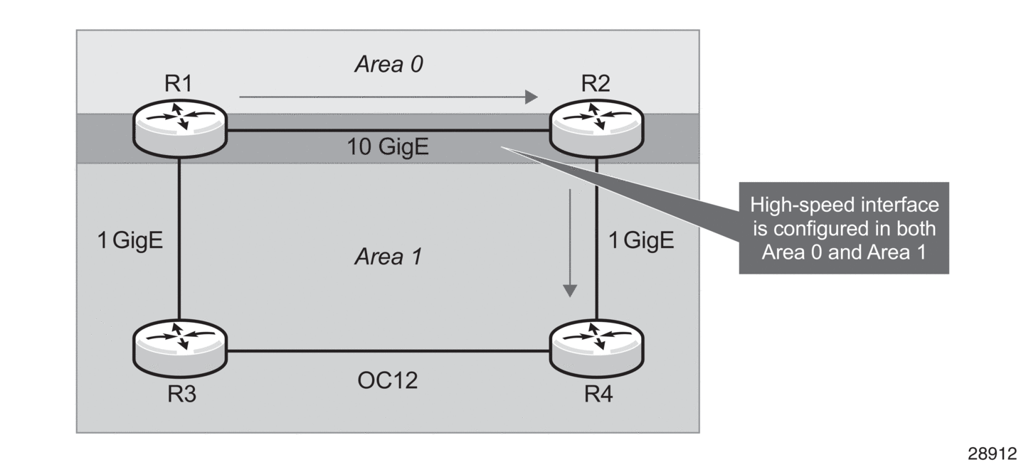
The 7705 SAR supports the use of a single IP interface in multiple areas as defined in RFC 5185, OSPF Multi-Area Adjacency. With multi-area adjacency, OSPF routers establish multiple adjacencies for different areas over a single logical interface. Each multi-area adjacency is announced as an unnumbered point-to-point link in the configured area by the routers connected to the link. For each area, one logical interface is treated as the primary interface and the other interfaces configured for the area are designated as secondary interfaces.
A logical interface can be configured as the primary interface for one area only. For any other area for which that interface is configured, the interface must be specified as secondary with the command config>router>ospf (ospf3)>area>interface ip-int-name secondary. It is recommended that area 0 (backbone area) be used for the primary interface association.
Multi-area adjacency is supported for OSPF and OSPFv3. It is also supported under the VPRN context.
4.1.13. OSPF Import Policies
By default, OSPF imports all the routes advertised via LSAs. Import policies allow routes that match a certain criteria, such as neighbor IP addresses, to be rejected. Users must use caution when applying import policies, since not using certain routes may result in network stability issues.
Import policies are supported within the base router context and the VPRN context. Import policies are not supported on OSPFv3.
4.2. Bidirectional Forwarding Detection (BFD) for OSPF
BFD is a simple protocol for detecting failures in a network. BFD uses a “hello” mechanism that sends control messages periodically to the far end and receives periodic control messages from the far end. BFD can detect device, link, and protocol failures.
BFD can be enabled using OSPFv2 (for IPv4) or OSPFv3 (for IPv6). Additionally, a network can be configured to use both OSPFv2 and OSPFv3.
When BFD is enabled on an OSPF interface, the state of the interface is tied to the state of the BFD session between the local node and remote (far-end) node. BFD is implemented in asynchronous mode only, meaning that neither end responds to control messages; rather, the messages are sent in the time period configured at each end.
If the configured number of consecutive BFD missed messages is reached, the link is declared down and OSPF takes the appropriate action (for example, generates an LSA update against the failed link or reroutes around the failed link).
Due to the lightweight nature of BFD, it can detect failures faster than other detection protocols, making it ideal for use in applications such as mobile transport.
4.3. Graceful Restart Helper
Graceful Restart and non-stop routing (NSR) both provide mechanisms that allow neighbor routers to handle a service interruption due to a CSM switchover. Data packets continue to be forwarded along known routes while the OSPF information is being restored or refreshed following the switchover.
With Graceful Restart, a router undergoing a switchover informs its adjacent neighbors and requests a grace period whereby traffic is still forwarded based on the last known good FIB while the router restarts. The neighbor must cooperate with the requesting router in order for the traffic to be forwarded. After the switchover, the neighbor relationships must be re-established.
With NSR (or high-availability service), routing neighbors are unaware of any event on the router performing a switchover. All activity switches to the inactive CSM, which maintains up-to-date routing information, so that routing topology and reachability are not affected. NSR is a more reliable and robust way of handling service interruptions than Graceful Restart.
The 7705 SAR supports NSR; therefore, Graceful Restart is not implemented on the router. However, to support neighbor routers that do not have high-availability service, the 7705 SAR supports Graceful Restart Helper. In Graceful Restart Helper mode, the 7705 SAR never requests graceful restart support. However, if a grace LSA is received from an OSPF neighbor, the 7705 SAR keeps the link toward that neighbor up and operational until the specified grace period in the grace LSA expires or the graceful restart is successful, whichever comes first.
4.4. LFA Protection Using Segment Routing Backup Node SID
One of the challenges in MPLS deployments across multiple IGP areas or domains, such as in seamless MPLS design, is the provisioning of FRR local protection in access and metro domains that make use of a ring, a square, or a partial mesh topology. In order to implement IP, LDP, or SR FRR in these topologies, the remote LFA feature must be implemented. Remote LFA provides a Segment Routing (SR) tunneled LFA next hop for an IP prefix, an LDP tunnel, or an SR tunnel. For prefixes outside of the area or domain, the access or aggregation router must push four labels: service label, BGP label for the destination PE, LDP/RSVP/SR label to reach the exit ABR/ASBR, and one label for the remote LFA next hop. Small routers deployed in these parts of the network have limited MPLS label stack size support.
Figure 12 illustrates the label stack required for the primary next-hop and the remote LFA next hop computed by aggregation node AGN2 for the inter-area prefix of a remote PE. For an inter-area BGP labeled unicast route prefix for which ABR1 is the primary exit ABR, AGN2 resolves the prefix to the transport tunnel of ABR1 and therefore, uses the remote LFA next hop of ABR1 for protection. The primary next hop uses two transport labels plus a s service label. The remote LFA next hop for ABR1 uses PQ node AGN5 and pushes three transport labels plus a service label.
Seamless MPLS with Fast Restoration requires up to four labels to be pushed by AGN2, as shown in Figure 12.
Figure 12: Label Stack for Remote LFA in Ring Topology

The objective of the LFA protection with a backup node segment ID (SID) feature is to reduce the label stack pushed by AGN2 for BGP labeled unicast inter-area prefixes. When link AGN2-AGN1 fails, packets are direct away from the failure and forwarded toward ABR2, which acts as the backup for ABR1 (and vice-versa when ABR2 is the primary exit ABR for the BGP labeled unicast inter-area prefix). This requires that ABR2 advertise a special label for the loopback of ABR1 that will attract packets normally destined for ABR1. These packets will be forwarded by ABR2 to ABR1 via the inter-ABR link.
As a result, AGN2 will push the label advertised by ABR2 to back up ABR1 on top of the BGP label for the remote PE and the service label. This keeps the label stack the same size for the LFA next hop to be the same size as that of the primary next-hop. It is also the same size as the remote LFA next hop for the local prefix within the ring.
4.4.1. Configuring LFA Using Backup Node SID
LFA using a backup node SID is enabled by configuring a backup node SID at an ABR/ASBR that acts as a backup to the primary exit ABR/ASBR of inter-area/inter-as routes learned as BGP labeled routes.
The user can enter either a label or an index for the backup node SID.
| Note: This feature only allows the configuration of a single backup node SID per IGP instance and per ABR/ASBR. In other words, only a pair of ABR/ASBR nodes can back up each other in an IGP domain. Each time the user invokes the above command within the same IGP instance, it overrides any previous configuration of the backup node SID. The same ABR/ASBR can, however, participate in multiple IGP instances and provide backup support within each instance. |
4.4.2. Detailed Operation of LFA Protection Using Backup Node SID
As shown in Figure 13, LFA for seamless MPLS supports environments where the boundary routers are either:
- ABR nodes that connect with IBGP multiple domains, each using a different area of the same IGP instance
- ASBR nodes that connect domains running different IGP instances and use IBGP within a domain and EBGP to the other domains
Figure 13: Backup ABR Node SID
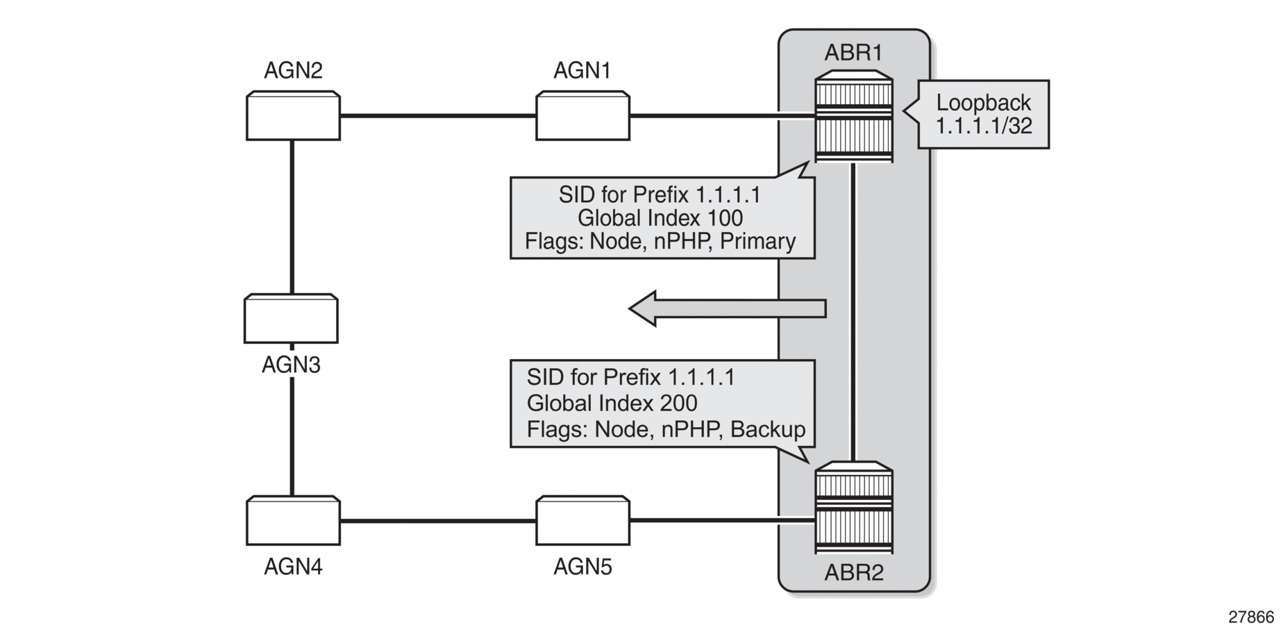
The following steps describe the configuration and behavior of LFA Protection using backup node SID:
- The user configures node SID 100 in ABR1 for its loopback prefix 1.1.1.1/32. This is the regular node SID. ABR1 advertises the prefix SID sub-TLV for this node SID in the IGP and installs the ILM using a unique label.
- Each router receiving the prefix sub-TLV for node SID 100 resolves it as described in Segment Routing in Shortest Path Forwarding. Changes to the programming of the backup NHLFE of node SID 100 based on receiving the backup node SID for prefix 1.1.1.1/32 are defined in Duplicate SID Handling.
- The user configures a backup node SID 200 in ABR2 for the loopback 1.1.1.1/32 of ABR1. The SID value must be different from that assigned by ABR1 for the same prefix. ABR2 installs the ILM, which performs a swap operation from the label of SID 200 to that of SID 100. The ILM must point to a direct link and next hop to reach 1.1.1.1/32 of ABR1 as its primary next hop. The IGP examines all adjacencies established in the same area as that of prefix 1.1.1.1/32 and determines which ones have ABR1 as a direct neighbor and with the best cost. If more than one adjacency has the best cost, the IGP selects the one with the lowest interface index. If there is no adjacency to reach ABR2, the prefix SID for the backup node is flushed and is not resolved. This is to prevent any other non-direct path being used to reach ABR1. As a result, any received traffic on the ILM of SID 200 traffic will be blackholed.
- If resolved, ABR2 advertises the prefix SID sub-TLV for this backup node SID 200 and indicates in the SR Algorithm field that a modified SPF algorithm, referred to as “Backup-constrained-SPF”, is required to resolve this node SID.
- Each router receiving the prefix sub-TLV for the backup node SID 200 performs the following steps.The following resolution steps do not require a CLI command to be enabled.
- The router determines which router is being backed up. This is achieved by checking the router ID owner of the prefix sub-TLV that was advertised with the same prefix but without the backup flag and which is used as the best route for the prefix. In this case, it should be ABR1. Then the router runs a modified SPF by removing node ABR1 from the topology to resolve the backup node SID 200. The primary next hop should point to the path to ABR2 in the counter clockwise direction of the ring.The router will not compute an LFA or a remote LFA for node SID 200 because the main SPF used a modified topology.
- The router installs the ILM and primary NHLFE for the backup node SID.Only a swap label operation is configured by all routers for the backup node SID. There is no push operation, and no tunnel for the backup node SID is added into the TTM.
- The router programs the backup node SID as the LFA backup for the SR tunnel to node SID of 1.1.1.1/32 of ABR1. In other words, each router overrides the remote LFA backup for prefix 1.1.1.1/32, which is normally PQ node AGN5.
- If the router is adjacent to ABR1, for example AGN1, it also programs the backup node SID as the LFA backup for the protection of any adjacency SID to ABR1.
- When node AGN2 resolves a BGP label route for an inter-area prefix for which the primary ABR exit router is ABR1, it will use the backup node SID of ABR1 as the remote LFA backup instead of the SID to the PQ node (AGN5 in this example) to save on the pushed label stack.AGN2 continues to resolve the prefix SID for any remote PE prefix that is summarized into the local area of AGN2 as usual. AGN2 programs a primary next hop and a remote LFA next hop. Remote LFA will use AGN5 as the PQ node and will push two labels, as it would for an intra-area prefix SID. There is no need to use the backup node SID for this prefix SID and force its backup path to go to ABR1. The backup path may exit from ABR2 if the cost from ABR2 to the destination prefix is shorter.
- If the user excludes a link from LFA in the IGP instance (config>router>ospf>area>interface>loopfree-alternate-exclude or config>router>isis>interface>loopfree-alternate-exclude), a backup node SID that resolves to that interface will not be used as a remote LFA backup in the same way as regular LFA or PQ remote LFA next-hop behavior.
- If the OSPF neighbor of a router is put into overload or if the metric of an OSPF interface to that neighbor is set to LSInfinity (0xFFFF), a backup node SID that resolves to that neighbor will not be used as a remote LFA backup in the same way as regular LFA or PQ remote LFA next hop behavior.
- If the IS-IS neighbor of a router is put into overload or if the metric of an IS-IS interface to that neighbor is set to overload max-metric (0xfffffe), a backup node SID that resolves to that neighbor will be used as a remote LFA backup in the same way as regular LFA or PQ remote LFA next hop behavior.

Note: Other routers in the network will not forward transit traffic to the router in overload.
- If the IS-IS interface to a neighbor is set to maximum link metric (0xffffff), a backup node SID that resolves to that neighbor will not be used as a remote LFA backup in the same way as regular LFA or PQ remote LFA next hop behavior.
- LFA policy is supported for IP next hops only. It is not supported with tunnel next hops such as IGP shortcuts or remote LFA tunnels. A backup node SID is also a tunnel next hop and therefore a user-configured LFA policy will not be applied to check constraints such as admin-groups and SRLG against the outgoing interface of the selected backup node SID.
4.4.3. Duplicate SID Handling
When the IGP issues or receives an LSA/LSP containing a prefix SID sub-TLV for a node SID or a backup node SID with a SID value that is a duplicate of an existing SID or backup node SID, the resolution in Table 32 is followed.
Table 32: Handling of Duplicate SIDs
Old LSA/LSP | New LSA/LSP | |||
Backup Node SID | Local Backup Node SID | Node SID | Local Node SID | |
Backup Node SID | Old | New | New | New |
Local Backup Node SID | Old | Equal | New | New |
Node SID | Old | Old | Equal/Old 1 | Equal/New 2 |
Local Node SID | Old | Old | Equal/Old 1 | Equal/Old 1 |
- Equal/Old means the following.
- If the prefix is duplicate, it is equal and no change is needed. Keep the old LSA/LSP.
- If the prefix is not duplicate, still keep the old LSA/LSP.
- Equal/New means the following.
- If the prefix is duplicate, it is equal and no change is needed. Keep the old LSA/LSP.
- If the prefix is not duplicate, pick a new prefix and use the new LSA/LSP.
Notes:
4.4.4. OSPF Control Plane Extensions
All routers supporting OSPF control plane extensions must advertise support of the new algorithm “Backup-constrained-SPF” of value 2 in the SR-Algorithm TLV, which is advertised in the Router Information Opaque LSA. This is in addition to the default supported algorithm “IGP-metric-based-SPF” of value 0. The following shows the encoding of the prefix SID sub-TLV to indicate a node SID of type backup and to indicate the modified SPF algorithm in the SR Algorithm field. The values used in the Flags field and in the Algorithm field are SR OS proprietary.
The new Algorithm (0x2) field and values are used by this feature.
Table 33 lists OSPF control plane extension field values.
Table 33: OSPF Control Plane Extension Fields
Field | Value |
Type | 2 |
Length | variable |
Flags | 1 octet field |
The following flags are defined; the “B” flag is new:
Table 34 lists OSPF control plane extension flag values.
Table 34: OSPF Control Plane Extension Flags
Flag | Description |
NP-Flag | No-PHP flag If set, the penultimate hop must not pop the prefix SID before delivering the packet to the node that advertised the prefix SID |
M-Flag | Mapping Server Flag If set, the SID is advertised from the Segment Routing Mapping Server functionality as described in I-D.filsfils-spring-segment-routing-ldp-interop |
E-Flag | Explicit-Null Flag If set, any upstream neighbor of the prefix SID originator must replace the prefix SID with a prefix SID having an Explicit-NULL value (0 for IPv4) before forwarding the packet. |
V-Flag | Value/Index Flag If set, the prefix SID carries an absolute value. If not set, the prefix SID carries an index. |
L-Flag | Local/Global Flag If set, the value/index carried by the prefix SID has local significance. If not set, then the value/index carried by this sub-TLV has global significance. |
B-Flag | This flag is used by the Protection using backup node SID feature. If set, the SID is a backup SID for the prefix. This value is SR OS proprietary. |
Other bits | Reserved These must be zero when sent and are ignored when received. |
MT-ID | Multi-Topology ID, as defined in RFC 4915 |
Algorithm | One octet identifying the algorithm the prefix SID is associated with. A value of (0x2) indicates the modified SPF algorithm, which removes from the topology the node that is backed up by the backup node SID. This value is SR OS proprietary. |
SID/Index/Label | Based on the V and L flags, it contains either:
|
4.4.5. Topology-Independent LFA for OSPF
OSPFv2 supports topology-independent LFA (TI-LFA), which improves the protection coverage of a network topology by computing and automatically instantiating a repair tunnel to a Q node that is not in the shortest path from the computing node. See Topology-Independent LFA for more information. The information in this section refers to IS-IS but also applies to OSPF.
4.5. LDP and IP Fast Reroute (FRR) for OSPF Prefixes
LDP Fast Reroute (FRR) provides local protection for an LDP FEC by precalculating and downloading a primary and a backup NHLFE for the FEC to the LDP FIB. The primary NHLFE corresponds to the label of the FEC received from the primary next hop as per the standard LDP resolution of the FEC prefix in the RTM. The backup NHLFE corresponds to the label received for the same FEC from a Loop-Free Alternate (LFA) next hop.
LDP FRR improves convergence in case of a local link or node failure in the network, by using the label-FEC binding received from the LFA next hop to forward traffic for a given prefix as soon as the primary next hop is not available. This means that a router resumes forwarding LDP packets to a destination prefix using the backup path without waiting for the routing convergence.
IP Fast Reroute (FRR) protects against link or node failures in an IP network by precalculating a backup route to use when the primary next hop is not available. Both routes are populated in the RTM. IP FRR uses an LFA backup next hop to forward in-transit IP packets as soon as the primary next hop failure is detected and the backup is invoked. This means that a node resumes forwarding IP packets to a destination prefix without waiting for the routing convergence.
Refer to RFC 5286, Basic Specification for IP Fast Reroute: Loop-Free Alternates, for more information on LFAs.
Refer to the 7705 SAR MPLS Guide “LDP Fast Reroute (FRR)” for more information on LDP FRR and to the 7705 SAR Router Configuration Guide, “IP Fast Reroute (FRR)” for more information on IP FRR.
LFAs are supported on IPv4 and IPv6 OSPF prefixes, VPN IPv4 OSPF prefixes, and on inter-area OSPF prefixes. LFAs are also supported on IPv4 IS-IS prefixes and on inter-level IS-IS prefixes. For information on LFA support for IS-IS prefixes, see LDP and IP Fast Reroute (FRR) for IS-IS Prefixes.
IP FRR also provides an LFA backup next hop for the destination prefix of a GRE tunnel used in an SDP or in VPRN auto-bind.
4.5.1. LFA Calculations
In addition to performing the Shortest Path First (SPF) calculation of the primary next hop, OSPF must calculate a backup next hop for all prefixes used by LDP to resolve FECs and for all prefixes used by IP to forward packets. The backup next hops are calculated to provide single link or node protection and to guarantee that when a failure occurs, forwarding traffic through the backup next hop will not result in a loop. These backup next hops are called Loop-Free Alternates (LFAs).
In general, in order to calculate LFAs for a specific destination (D), a router must know the following information:
- the shortest-path distance from the calculating router (source) to the destination (SP(S,D))
- the shortest-path distance from the router’s OSPF neighbors to the destination (SP(N,D))
- the shortest-path distance from the router’s OSPF neighbors to itself (SP(N,S))
A neighbor (N) can provide an LFA only if:
SP(N,D) < SP(N,S) + SP(S,D)
This is known as loop-free criterion.
Figure 14 shows an example of a backup route resulting in a micro-loop. In the example, PE-1 uses PE-2 as its next hop to reach PE-3. The total cost to reach PE-3 via PE-2 is 9. If the link between PE-1 and PE-2 fails, PE-1 can try to use PE-4 as its next hop to reach PE-3. However, the metric between PE-4 and PE-3 is 30. From the perspective of PE-4, forwarding traffic via the PE-1 and PE-2 path to PE-3 is more viable, as the cost is 17 (8 + 5 + 4) versus the direct link cost of 30. Therefore, if PE-1 forwards the traffic to PE-4 in order to reach PE-3, PE-4 forwards it back to PE-1, creating a micro-loop, until the routing protocols converge and declare the link between PE-1 and PE-2 to be down. PE-4 would then be forced to take the direct PE-3 link to reach PE-3 as there is no other alternative. Because PE-4 does not meet the loop-free criterion, it cannot be used as a valid LFA.
Figure 14: Backup Routes Resulting in Micro-loops
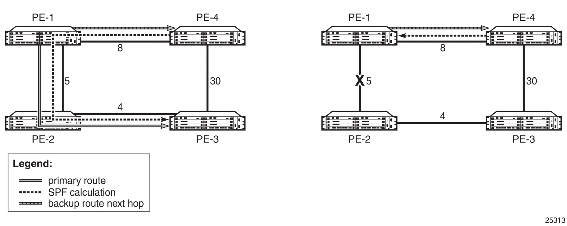
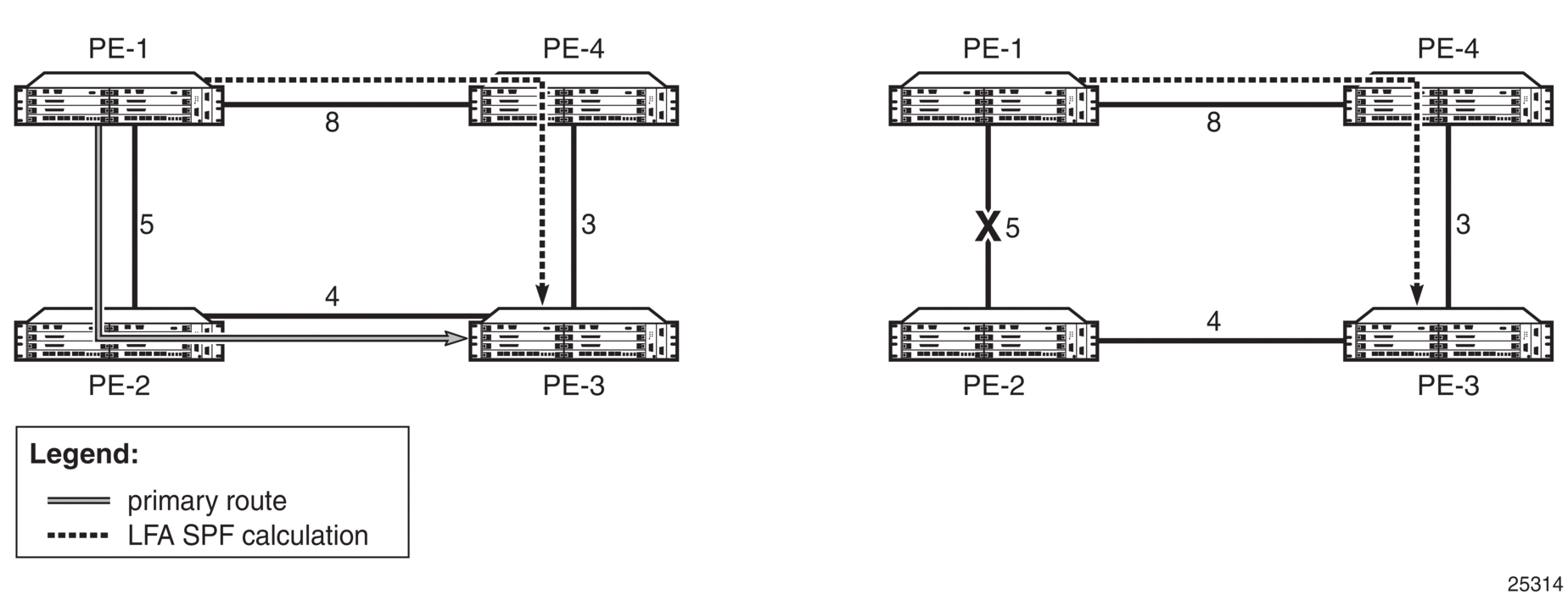
Figure 15 shows an example of an LFA backup route. In this example, PE-1 again uses PE-2 as its next hop to reach PE-3. The total cost to reach PE-3 via PE-2 is 9. If the link between PE-1 and PE-2 fails, PE-1 can use PE-4 to reach PE-3. From the perspective of PE-4, the direct route to PE-3 is a viable route, as the cost is 3 versus the cost of forwarding traffic via PE-1 (17). Using the direct route does not cause micro-loops and meets the loop-free criterion; therefore, PE-4 can be used as a valid LFA.
Figure 15: LFA Backup Route
4.5.1.1. Selection Algorithm
For a point-to-point interface, if SPF finds multiple LFA next hops for a given primary next hop, the selection algorithm is as follows:
- SPF will pick the node-protect type over the link-protect type.
- If there is more than one LFA next hop within the selected type, it will pick one based on the least cost.
- If there is more than one LFA next hop with the same cost, SPF will select the first one. This is not a deterministic selection and will vary for each SPF calculation.
For a broadcast interface, a node-protect LFA is not necessarily a link-protect LFA if the path to the LFA next hop goes over the same pseudonode as the primary next hop. Similarly, a link-protect LFA may not guarantee link protection if it goes over the same pseudonode as the primary next hop.
When SPF finds multiple LFA next hops for a given primary next hop, the selection algorithm is as follows:
- The algorithm splits the LFA next hops into two sets:
- the first set consists of LFA next hops that do not go over the pseudonode used by the primary next hop
- the second set consists of LFA next hops that do go over the pseudonode used by the primary next hop
- If there is more than one LFA next hop in the first set, it will pick the node-protect type over the link-protect type.
- If there is more than one LFA next hop within the selected type, it will pick one based on the least cost.
- If there is more than one LFA next hop with the same cost, SPF will select the first one from the remaining set. This is not a deterministic selection and will vary for each SPF calculation.
- If no LFA next hop results from step 4, SPF will rerun steps 2 to 4 using the second set.
| Note: A node-protect LFA that does not guarantee link protection can still be selected as a last resort; as well, a link-protect LFA that does not guarantee node protection can still be selected as a last resort. |
Both the calculated primary next hop and LFA next hop for a given prefix are programmed into the RTM.
4.5.1.2. LFA Configuration
To enable LFA for OSPF prefixes, enter the following command at the OSPF instance level:
config>router>ospf>loopfree-alternate
or
config>router>ospf3>loopfree-alternate
Next, enable FRR for LDP and/or IP by entering the following commands:
config>router>ldp>fast-reroute
config>router>ip-fast-reroute
These commands instruct the OSPF SPF algorithm to precalculate a primary next hop and LFA next hop for every learned prefix, in order to provide FRR to LDP FEC packets and/or IP packets.
To exclude all interfaces within a specific OSPF area or to exclude a specific IP interface from being included in the LFA SPF calculation, enter the following commands:
config>router>ospf>area>loopfree-alternate-exclude
or
config>router>ospf3>area>loopfree-alternate-exclude
config>router>ospf>area>interface>loopfree-alternate-exclude
or
config>router>ospf3>area>interface>loopfree-alternate-exclude
If IGP shortcuts are also enabled, any LSPs with a destination address in that OSPF area are not included in the LFA SPF calculation.
If an interface is excluded from the LFA SPF, it is excluded in all areas. However, the loopfree-alternate-exclude command can only be executed under the area in which the specified interface is primary. When the command is executed, the interface is excluded in that area and in all other areas where the interface is secondary. If the user attempts to execute the command under an area where the interface is secondary, the command will fail.
| Note: The loopfree-alternate and loopfree-alternate-exclude commands are also supported for OSPF and OSPFv3 within a VPRN service. |
4.5.2. IGP Shortcuts (RSVP-TE Tunnels)
Micro-loops, especially in ring topologies, are typically unavoidable. As the number of nodes in a ring increases, the chance of micro-loops occurring also increases. In cases where a valid directly connected next hop cannot be ensured, remote LFAs can be used. Remote LFAs are non-directly connected LFA next hops that are reached via IGP shortcuts.
IGP shortcuts are an MPLS functionality where LSPs are treated like physical links within IGPs; that is, LSPs can be used for next hop reachability. If an RSVP-TE LSP is used as a shortcut by OSPF or IS-IS, it is included in the SPF calculation as a point-to-point link for both primary and LFA next hops. It can also be advertised to neighbors so that the neighboring nodes can also use the links to reach a destination via the advertised next hop.
IGP shortcuts can be used to simplify remote LFA support and simplify the number of LSPs required in a ring topology.
IGP shortcut functionality provides two options:
- LFA-protect optionThis option allows an LSP to be included in both the main SPF and the Loop-Free Alternate (LFA) SPF algorithm. For a given prefix, the LSP can be used either as a primary next hop or as an LFA next hop, but not both.If the main SPF calculation selects a tunneled primary next hop for a prefix, the LFA SPF calculation will not select an LFA next hop for this prefix and the protection of this prefix will rely on the RSVP LSP FRR protection.If the main SPF calculation selects a direct primary next hop, the LFA SPF calculation will select an LFA next hop for this prefix but will prefer a direct LFA next hop over a tunneled LFA next hop.
- LFA-only optionThis option allows an LSP to be included in the LFA SPF algorithm only, which means that the introduction of IGP shortcuts does not affect the main SPF decision. For a given prefix, the main SPF calculation always selects a direct primary next hop. The LFA SPF calculation will select an LFA next hop for this prefix but will prefer a direct LFA next hop over a tunneled LFA next hop.
4.5.2.1. Selection Algorithm
If there are multiple LFA next hops for a primary next hop, the selection algorithm is as follows:
- The algorithm splits the LFA next hops into two sets:
- the first set consists of direct LFA next hops
- the second set consists of tunneled LFA next hops after excluding the LSPs that use the same outgoing interface as the primary next hop
- The algorithm continues with the first set if it is not empty; otherwise, it continues with the second set.
- If the second set is used, the algorithm selects the tunneled LFA next hop whose endpoint corresponds to the node advertising the prefix:
- if more than one tunneled next hop exists, it selects the one with the lowest LSP metric
- if more than one tunneled next hop still exists, it selects the one with the lowest tunnel ID
- if none is available, it continues with rest of the tunneled LFAs in the second set
- Within the selected set, the algorithm splits the LFA next hops into two sets:
- the first set consists of LFA next hops that do not go over the pseudonode used by the primary next hop
- the second set consists of LFA next hops that go over the pseudonode used by the primary next hop
- If there is more than one LFA next hop in the selected set, it will pick the node-protect type over the link-protect type.
- If there is more than one LFA next hop within the selected type, it will pick one based on the least total cost for the prefix. For a tunneled next hop, that means the LSP metric plus the cost of the LSP endpoint to the destination of the prefix.
- If there is more than one LFA next hop within the selected type in the first set (ECMP is configured), it will select the first direct next hop from the remaining set. This is not a deterministic selection and will vary for each SPF calculation.
- If there is more than one LFA next hop within the selected type in the second set (ECMP is configured), it will pick the tunneled next hop with the lowest cost from the endpoint of the LSP to the destination prefix. If there remains more than one next hop, it will pick the tunneled next hop with the lowest tunnel ID.
4.5.2.2. Forwarding Adjacency
The forwarding adjacency feature allows OSPF to advertise an RSVP-TE LSP as a link so that other routers in the network can include it in the SPF calculations. The RSVP-TE is advertised as an unnumbered point-to-point link and the link-state advertisement (LSA) has no traffic engineering opaque sub-TLVs as per RFC 3906, Calculating Interior Gateway Protocol (IGP) Routes Over Traffic Engineering Tunnels.
The forwarding adjacency feature can be enabled independently from the IGP shortcut feature. If both features are enabled for a given OSPF instance, forwarding adjacency takes precedence.
When forwarding adjacency is enabled, each node advertises a point-to-point unnumbered link for each best-metric tunnel to the router ID of any endpoint node. The node does not include the tunnels as IGP shortcuts in the SPF calculation directly. Instead, when the LSA advertising the corresponding point-to-point unnumbered link is installed in the local routing database, the node performs an SPF calculation using the link like any other link LSA. The link bidirectional check requires that a regular link or tunnel link exist in the reverse direction for the tunnel to be used in SPF calculations.
4.5.2.3. IGP Shortcut Configuration
To enable the use of IGP shortcuts by OSPF, enter the following command at the OSPF instance level:
config>router>ospf>rsvp-shortcut
To enable forwarding adjacency, enter the following command at the OSPF instance level:
config>router>ospf>advertise-tunnel-link
To enable the use of an RSVP-TE LSP by OSPF as a shortcut or as a forwarding adjacency for resolving IGP routes, enter the following command:
config>router>mpls>lsp>igp-shortcut
When the rsvp-shortcut or advertise-tunnel-link option is enabled at the OSPF instance level, all RSVP-TE LSPs originating on this node are eligible by default as long as the destination address of the LSP, as configured with the config>router> mpls>lsp>to command, corresponds to a router ID of a remote node. A specific LSP can be excluded from being used as a shortcut or forwarding adjacency with the no form of the igp-shortcut command.
4.5.3. LFA SPF Policies
An LFA SPF policy allows the user to apply specific criteria to the selection of a LFA backup next hop for a subset of prefixes that resolve to a specific primary next hop. The 7705 SAR supports the following LFA SPF policy constraints:
- admin group
- shared risk link group (SRLG)
- protection type
- next hop type
A route next hop policy template must first be created under the global router context. The template contains criteria for the policies in the preceding list.
The template is then applied to prefixes protected by LFA. Each instance of OSPF can apply the same policy template to one or more prefixes and interfaces. If a template is modified, OSPF re-evaluates it for any changes and, if necessary, schedules a new LFA SPF to recalculate the LFA next hop for any prefixes associated with the template.
As a related feature, prefixes that match a prefix entry in a prefix policy can be excluded from the LFA SPF calculation. If a prefix is excluded, it is not included in the LFA SPF calculation, regardless of its priority. Prefix policies are created with the config>router>policy-options>prefix-list command (for information on prefix lists, refer to the 7705 SAR Router Configuration Guide, “Route Policies”.
4.5.3.1. LFA SPF Policy Configuration
To create a route next hop policy template, enter the following command:
config>router>route-next-hop-policy template
Configure the template with policy constraints for the items in the preceding list.
| Note: To configure constraints for admin groups and SRLG groups, these groups must already be created in the config>router>if-attribute>admin-group and config>router>if-attribute>srlg-group contexts. |
Next, apply the template to OSPF interfaces by entering the following command:
config>router>ospf>area>interface>lfa-policy-map>route-nh-template
or
config>router>ospf3>area>interface>lfa-policy-map>route-nh-template
The template is applied to all prefixes using the specified interface name.
When a route next hop policy template is applied to an interface, it is applied in all areas. However, the route-nh-template command can only be executed under the area in which the specified interface is primary. When the command is executed, the template is applied in that area and in all other areas where the interface is secondary. If the user attempts to execute the command under an area where the interface is secondary, the command will fail.
Optionally, exclude prefixes in a prefix policy from the LFA SPF calculation by entering the following command:
config>router>ospf>loopfree-alternate-exclude prefix-policy
or
config>router>ospf3>loopfree-alternate-exclude prefix-policy
| Note: The lfa-policy-map and loopfree-alternate-exclude commands are also supported for OSPF within a VPRN service. |
4.6. Preconfiguration Requirements
The router ID must be available before OSPF can be configured. The router ID is a 32-bit IP address assigned to each router running OSPF. This number uniquely identifies the router within an AS. OSPF routers use the router IDs of the neighbor routers to establish adjacencies. Neighbor IDs are learned when Hello packets are received from the neighbor.
Before configuring OSPF parameters, ensure that the router ID is derived by one of the following methods:
- define the value using the config>router>router-id ip-address command
- define the system interface using the config>router>interface ip-int-name command (used if the router ID is not specified with the config>router>router-id ip-address command)A system interface must have an IP address with a 32-bit subnet mask. The system interface is assigned during the primary router configuration process when the interface is created in the logical IP interface context.
- if you do not specify a router ID, the last 4 bytes of the MAC address are used
4.7. OSPF Configuration Process Overview
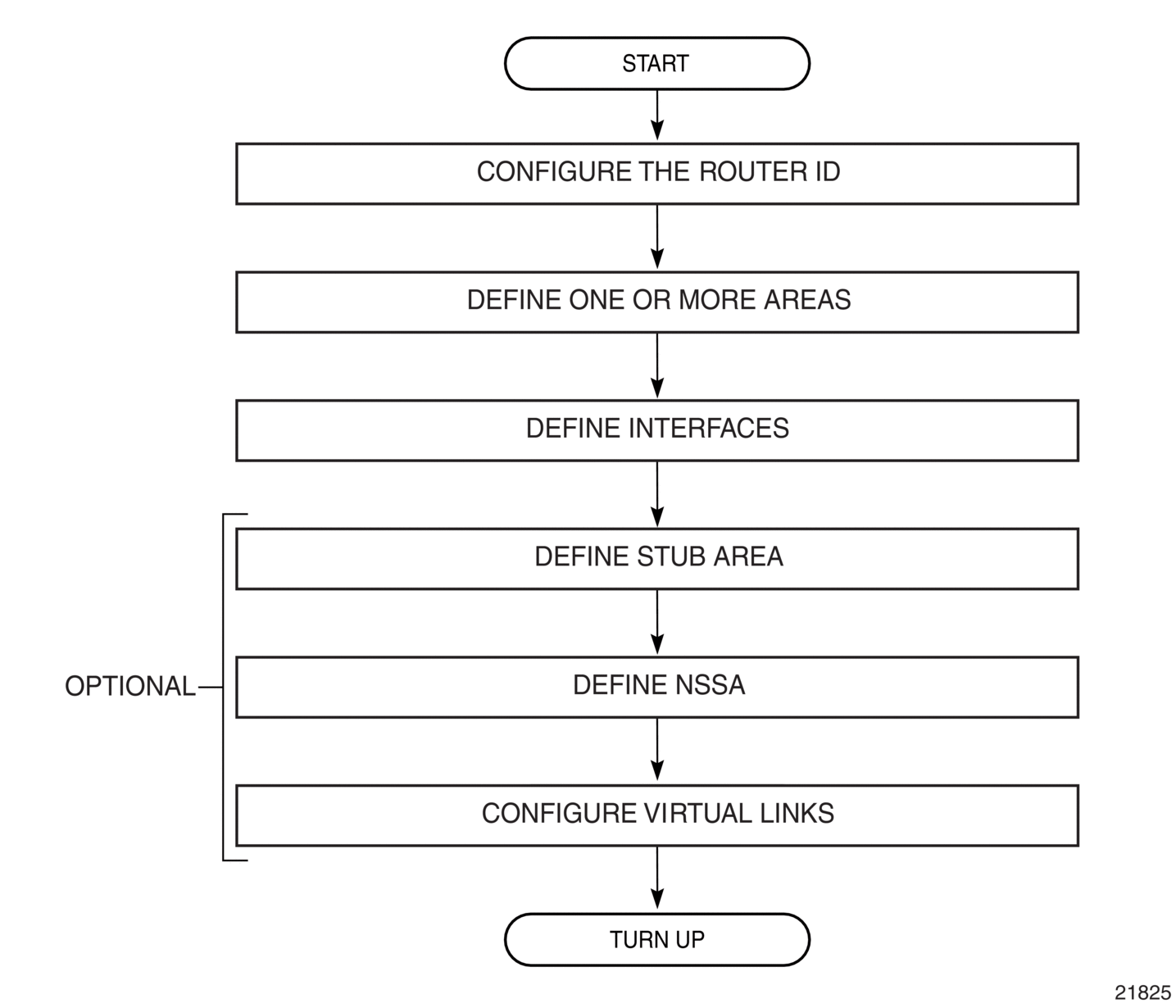
Figure 16 displays the process to provision basic OSPF parameters.
Figure 16: OSPF Configuration Process
4.8. Configuration Notes
4.8.1. General
- Before OSPF can be configured, the router ID must be configured.
- The basic OSPF configuration includes at least one area and an associated interface.
- All default and command parameters can be modified.
- By default, a router has no configured areas.
- The base OSPF instance is created in the administratively enabled state.
4.8.2. Reference Sources
For information on supported IETF drafts and standards, as well as standard and proprietary MIBs, refer to Standards and Protocol Support.