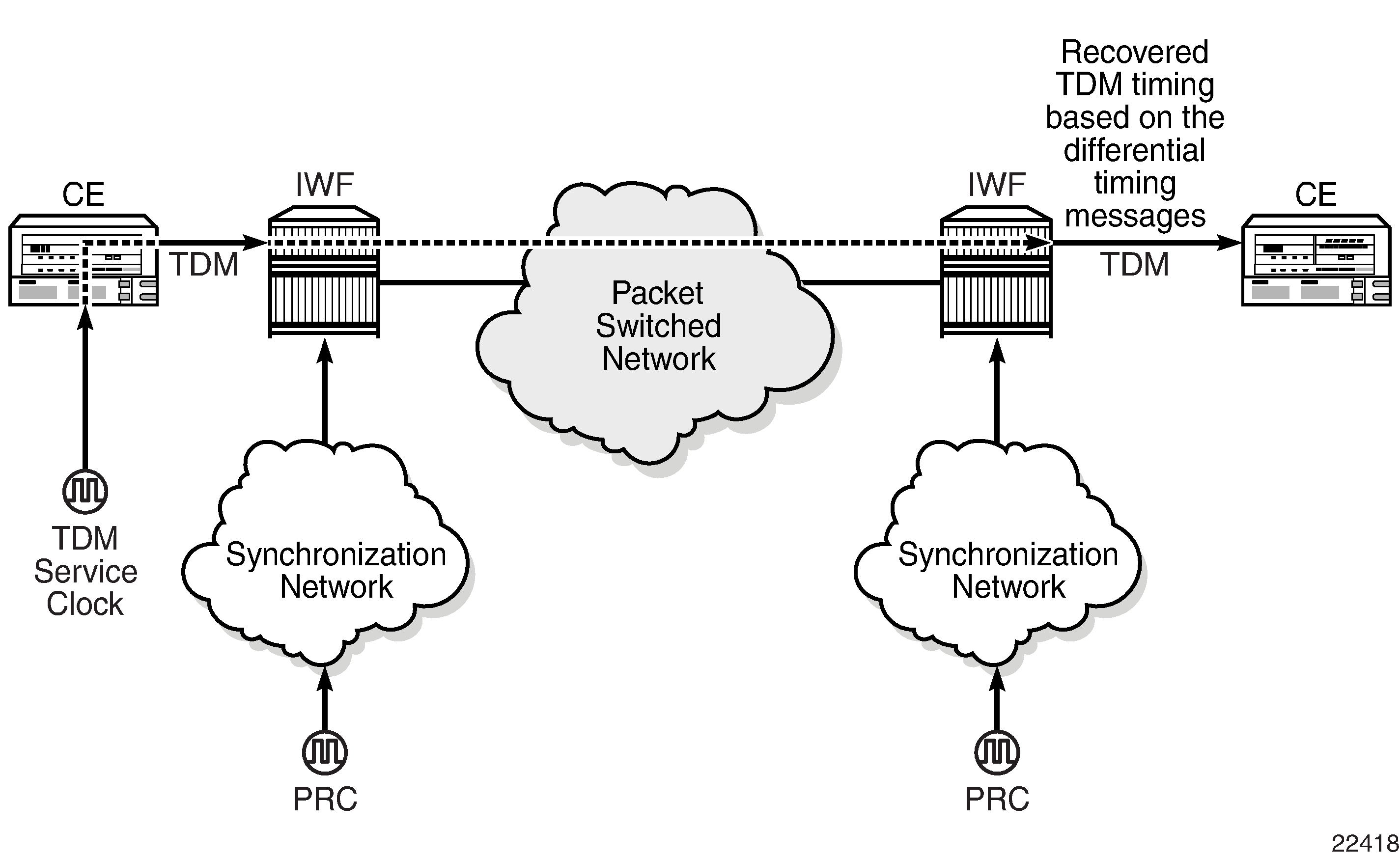
Differential Clock Recovery (DCR) is an alternative method to ACR to maintain the service clock across the packet network for a circuit emulated service. DCR is supported on:
-
16-port T1/E1 ASAP Adapter card
-
32-port T1/E1 ASAP Adapter card
-
4-port OC3/STM1 / 1-port OC12/STM4 Adapter card (DS1/E1 channels)
-
4-port DS3/E3 Adapter card (clear channel DS3/E3 ports and DS1/E1 channels on channelized DS3 ports (E3 ports cannot be channelized)); DCR on DS1/E1 channels is supported only on the first three ports of the card
-
7705 SAR-M (variants with T1/E1 ports)
-
7705 SAR-A (variant with T1/E1 ports)
-
T1/E1 ports of the 4-port T1/E1 and RS-232 Combination module
-
T1/E1 ports on the 7705 SAR-X
In addition, DCR is supported between TDM SAPs and Ethernet SAPs and between TDM SAPs and spoke SDPs in a MEF 8 configuration for the above platforms, adapter cards, and modules. Refer to the 7705 SAR Services Guide, ‟MEF 8”, for information on MEF 8.
DCR is not supported on DS1 or E1 channels that have CAS signaling enabled.
DCR uses channel group 1 for timing recovery. If a T1 or E1 port is channelized, all TDM PWs that share the port use the timing recovered from channel group 1.
To enable DCR, the network must have a common clock between the routers performing the TDM-to-packet interworking function or between the two terminating SAPs or SAP/spoke SDP using MEF 8. The common clock can come from two PRC-traceable clocks or one clock that is made available to both ends, such as the transmitted clock of a SONET/SDH or synchronous Ethernet port.
In each direction, the service clock is compared to the common clock and the difference is encoded into the RTP header in the TDM PW overhead. At the other end of the network, the original service clock is reproduced by comparing the common clock to the frequency difference in the RTP header. Figure: Differential Clock Recovery on a Network shows an example of a network using DCR.

RTP headers are disabled by default and must be enabled for all circuit emulation services that require DCR. RTP must be enabled for the TDM PW that uses channel group 1. All channel groups on the same DS1 or E1 channel must be configured for the same mode of operation.
To achieve the best DCR performance, it is recommended that you use a Layer 1 network synchronization method to ensure the common clock has the best stability. If a timing-over-packet technique is used to transfer the common clock, then the number and type of nodes, the traffic profile, and the temperature variations will affect DCR synchronization performance. As well, a packet rate of at least 200 pps is recommended (up to 4000 pps is supported). Packet rates lower than 200 pps may affect system performance.