The 7705 SAR supports boundary clock PTP devices in both master and slave states. IEEE 1588v2 can function across a packet network that is not PTP-aware; however, the performance may be unsatisfactory and unpredictable. PDV across the packet network varies with the number of hops, link speeds, usage rates, and the inherent behavior of the routers. By using routers with boundary clock functionality in the path between the grand master clock and the slave clock, one long path over many hops is split into multiple shorter segments, allowing better PDV control and improved slave performance. This allows PTP to function as a valid timing option in more network deployments and allows for better scalability and increased robustness in specific topologies, such as rings.
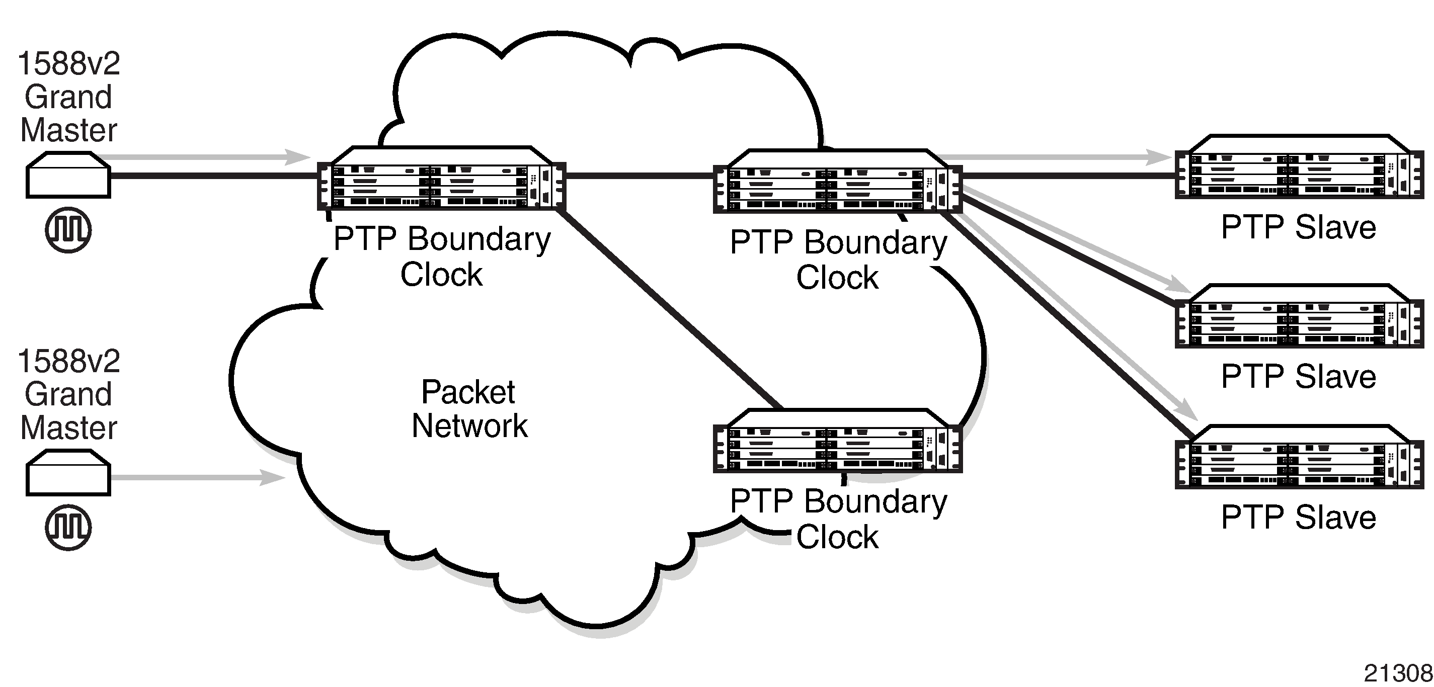
Boundary clocks can simultaneously function as a PTP slave of an upstream grand master (ordinary clock) or boundary clock, and as a PTP master of downstream slaves (ordinary clock) and/or boundary clocks. Figure: Boundary Clock shows the operation of a boundary clock.
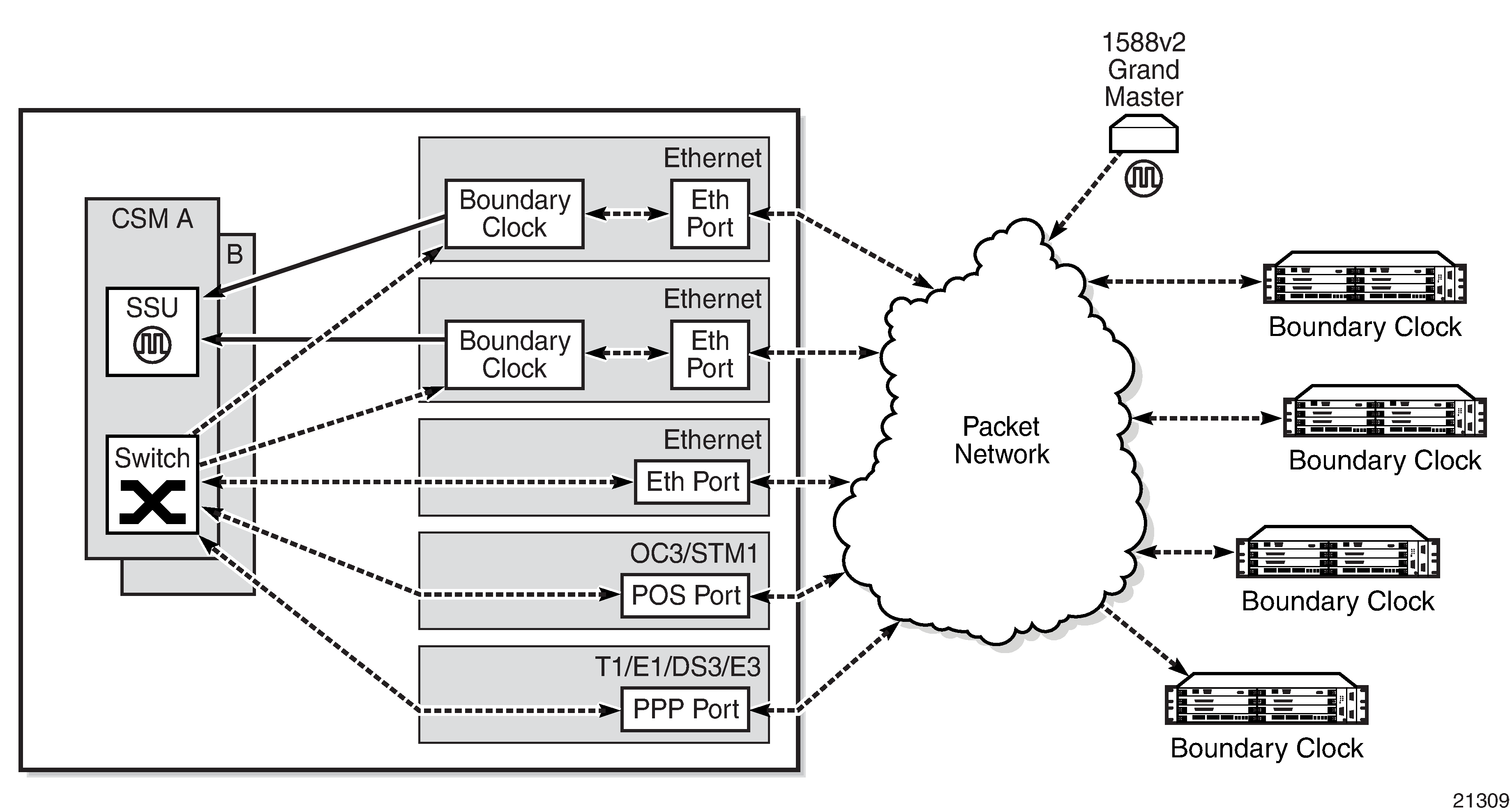
The PTP boundary clock capability is implemented on the Ethernet ports of the platforms listed in Table: IEEE 1588v2 PTP Support per Fixed Platform and on the cards listed in Table: IEEE 1588v2 PTP Support per Card on the 7705 SAR-8 Shelf V2 and 7705 SAR-18 .
The 7705 SAR-8 Shelf V2 can support up to six boundary clocks and the 7705 SAR-18 can support up to eight boundary clocks. The fixed platforms listed in Table: IEEE 1588v2 PTP Support per Fixed Platform can each support one boundary clock.
Each PTP boundary clock is configured for a specific slot where the card (see Table: IEEE 1588v2 PTP Support per Card on the 7705 SAR-8 Shelf V2 and 7705 SAR-18 ) or Ethernet port (see Table: IEEE 1588v2 PTP Support per Fixed Platform) performs the boundary clock function. On the 7705 SAR-M, 7705 SAR-H, 7705 SAR-Hc, 7705 SAR-A, 7705 SAR-Ax, and 7705 SAR-Wx, this slot is always 1/1. On the 7705 SAR-X, this slot is always either 1/2 or 1/3. When the 7705 SAR-M is receiving PTP packets on a 2-port 10GigE (Ethernet) module, its PTP clock continues to use slot 1/1. Each boundary clock is also associated with a loopback address for the router; however, the IP interface configured on a 2-port 10GigE (Ethernet) module cannot be associated with a boundary clock.
Each boundary clock can be peered with up to 50 slaves, boundary clocks, or grand master clocks. The IP addresses of these peers can be statically configured via CLI or dynamically accepted via PTP signaling messages. A statically configured peer may displace a dynamic peer on a particular PTP port. If there are fewer than 50 peers, that dynamic peer can signal back and be granted a different PTP-port instance.
Figure: Boundary Clock Operation shows an example of boundary clock operation.