The IEEE 1588v2 standard synchronizes the frequency and time from a master clock to one or more slave clocks over a packet stream. This packet-based synchronization can be over UDP/IP or Ethernet and can be unicast (for IP) or multicast (for Ethernet). For UDP/IP, both IPv4 and IPv6 unicast mode with unicast negotiation is supported.
As part of the basic synchronization timing computation, a number of event messages are defined for synchronization messaging between the PTP slave clock and PTP master clock. A one-step or two-step synchronization operation can be used, with the two-step operation requiring a follow-up message after each synchronization message. Currently, only one-step operation is supported when the 7705 SAR is a master clock; PTP frequency and time can be recovered from both one-step and two-step operation when the 7705 SAR is acting as a slave or boundary clock.
For IPv4, the two-step operation is optional. For IPv6, the two-step operation is a mandatory requirement for the 7705 SAR.
Two-step operation does not apply if PTP packets are routed over a physical port on the 7705 SAR-X or on the 6-port Ethernet 10Gbps Adapter card.
In one-step operation, a timestamp is inserted in the synchronization message when the packet is transmitted to the slave clock. In two-step operation, the timestamp is sent in the follow-up message. If the timestamp is changed in the synchronization message, the checksum field is recomputed. Because the checksum field is a mandatory field for IPv6 (optional for IPv4), the 7705 SAR requires the timestamp to be sent separately to avoid potential checksum corruption in the packet.
During startup, the PTP slave clock receives the synchronization messages from the PTP master clock before a network delay calculation is made. Before any delay calculation, the delay is assumed to be zero. A drift compensation is activated after a number of synchronization message intervals occur. The expected interval between the reception of synchronization messages is user-configurable.
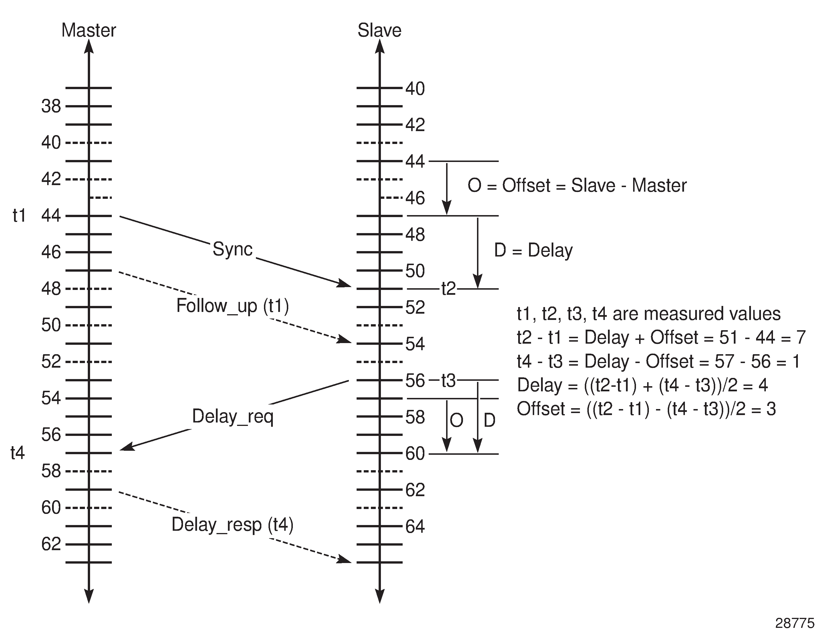
The basic synchronization timing computation between the PTP slave clock and PTP best master is illustrated in Figure: PTP Slave Clock and Master Clock Synchronization Timing Computation. This figure illustrates the offset of the slave clock referenced to the best master signal during startup.