The PTP ordinary clock with slave capability on the 7705 SAR provides an option to reference a Stratum-1 traceable clock across a packet switched network. The recovered clock can be referenced by the internal SSU and distributed to all slots and ports.
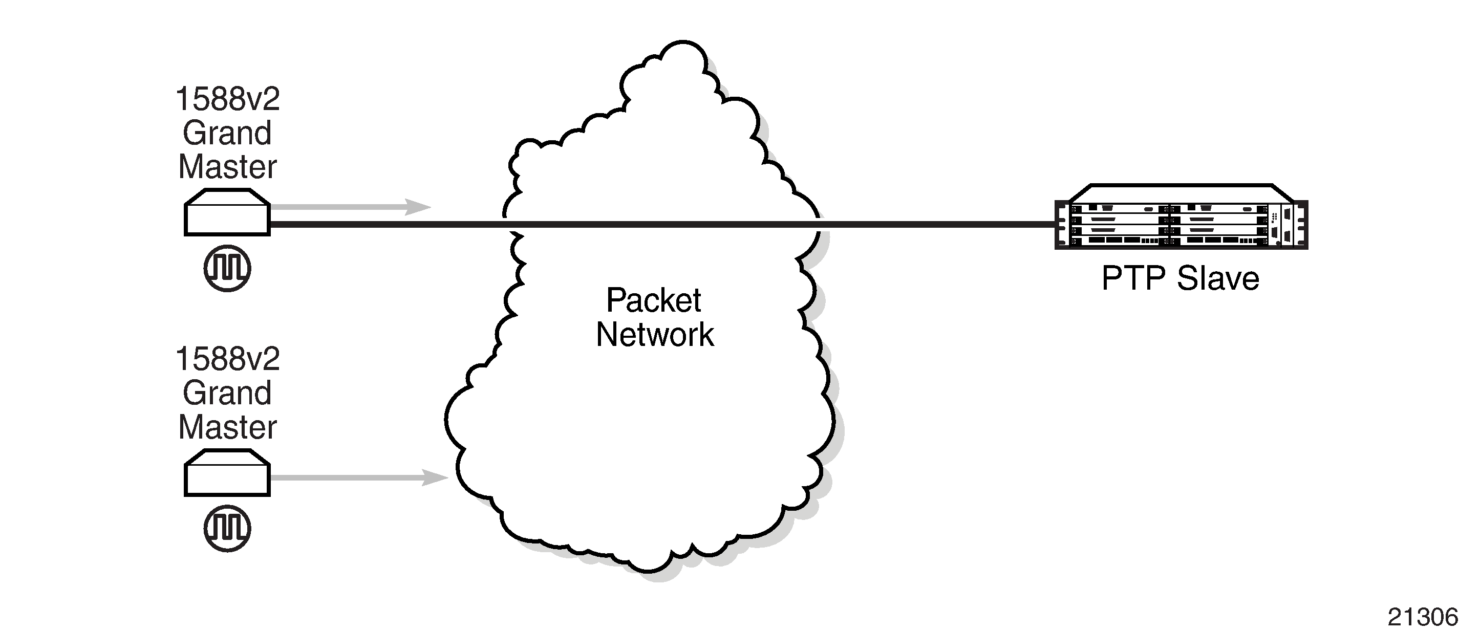
Figure: Slave Clock shows a PTP ordinary slave clock network configuration.
The PTP slave capability is implemented on the Ethernet ports of the platforms listed in Table: IEEE 1588v2 PTP Support per Fixed Platform and on the cards listed in Table: IEEE 1588v2 PTP Support per Card on the 7705 SAR-8 Shelf V2 and 7705 SAR-18 .
The 7705 SAR-8 Shelf V2 can support up to six slave clocks and the 7705 SAR-18 can support up to eight slave clocks.
All other fixed platforms listed in Table: IEEE 1588v2 PTP Support per Fixed Platform can support up to two PTP clocks when one of those clock types is configured as transparent; otherwise, they support only one slave clock.
Each slave clock can provide a separate frequency reference to the SSU.
Figure: Ordinary Slave Clock Operation shows the operation of an ordinary PTP clock in slave mode.
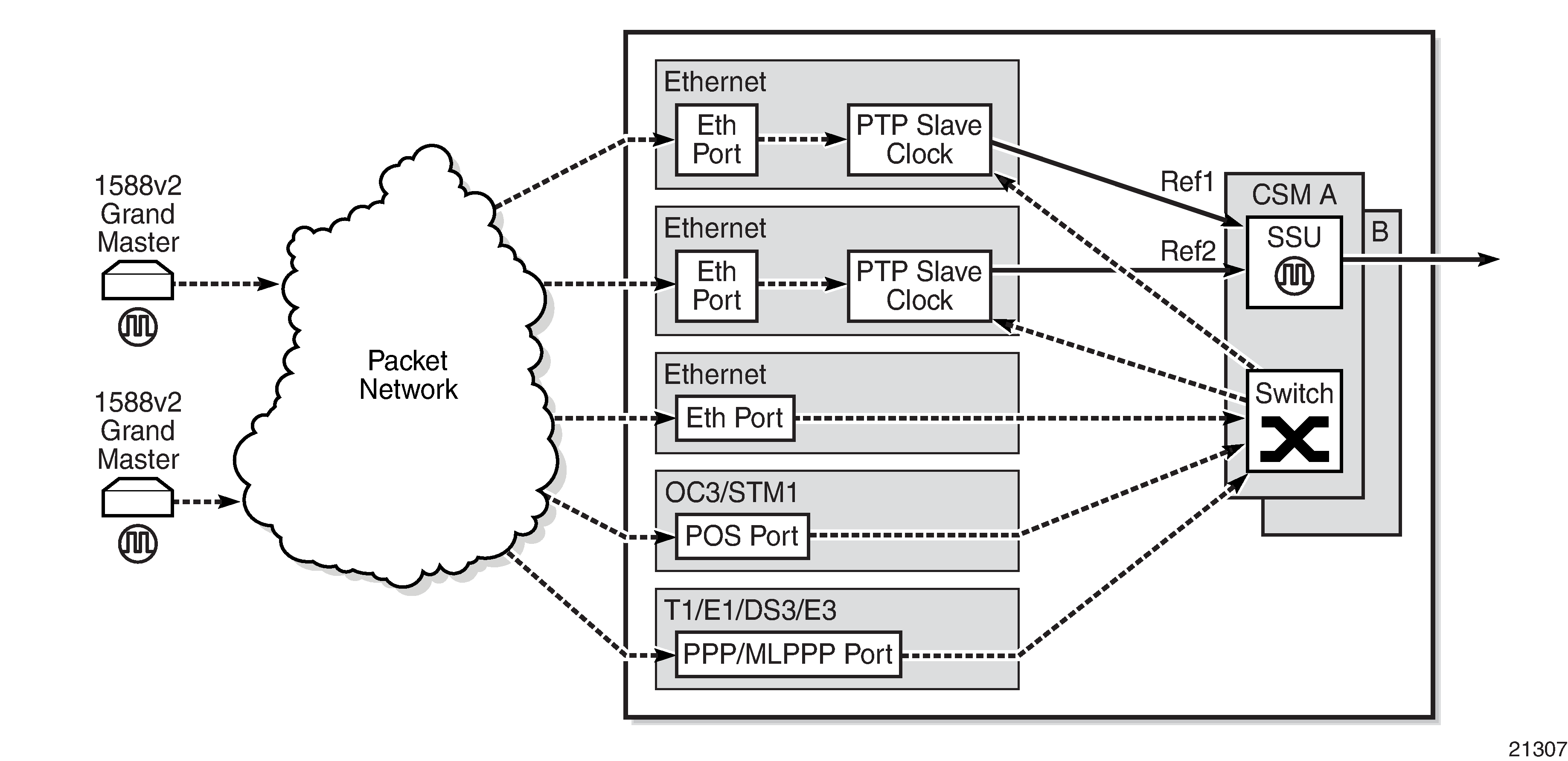
Each PTP ordinary slave clock is configured for a specific slot where the card (see Table: IEEE 1588v2 PTP Support per Card on the 7705 SAR-8 Shelf V2 and 7705 SAR-18 ) or Ethernet port (see Table: IEEE 1588v2 PTP Support per Fixed Platform) performs the slave function. On the 7705 SAR-M, 7705 SAR-H, 7705 SAR-Hc, 7705 SAR-A, 7705 SAR-Ax, and 7705 SAR-Wx, this slot is always 1/1. On the 7705 SAR-X, this slot is always either 1/2 or 1/3. When the 7705 SAR-M is receiving PTP packets on the 2-port 10GigE (Ethernet) module, its PTP clock continues to use slot 1/1. Each slave is also associated with an IP interface on a specific port, adapter card, or loopback address for the router; however, the IP interface configured on a 2-port 10GigE (Ethernet) module cannot be associated with a slave clock.
For best performance, the network should be designed so that the IP messaging between the master clock and the slave clock ingresses and egresses through a port where the slave is configured. If the ingress and egress flow of the PTP messages is via a different port or adapter card on the 7705 SAR, then the packets are routed through the fabric to the Ethernet card with the PTP slave.
It is possible that the PTP IP packets may be routed through another Ethernet port/VLAN, OC3/STM1 or OC12/STM4 clear channel POS, OC3/STM1 or OC12/STM4 channelized MLPPP, DS3/E3 PPP, or DS1/E1 MLPPP. The PTP slave performance may be slightly worse in this case because of the extra PDV experienced through the fabric. Packets are routed this way only if the clock is configured with a loopback address. If the clock is configured with an address tied to a physical port, the packets arrive on that physical port as described above.