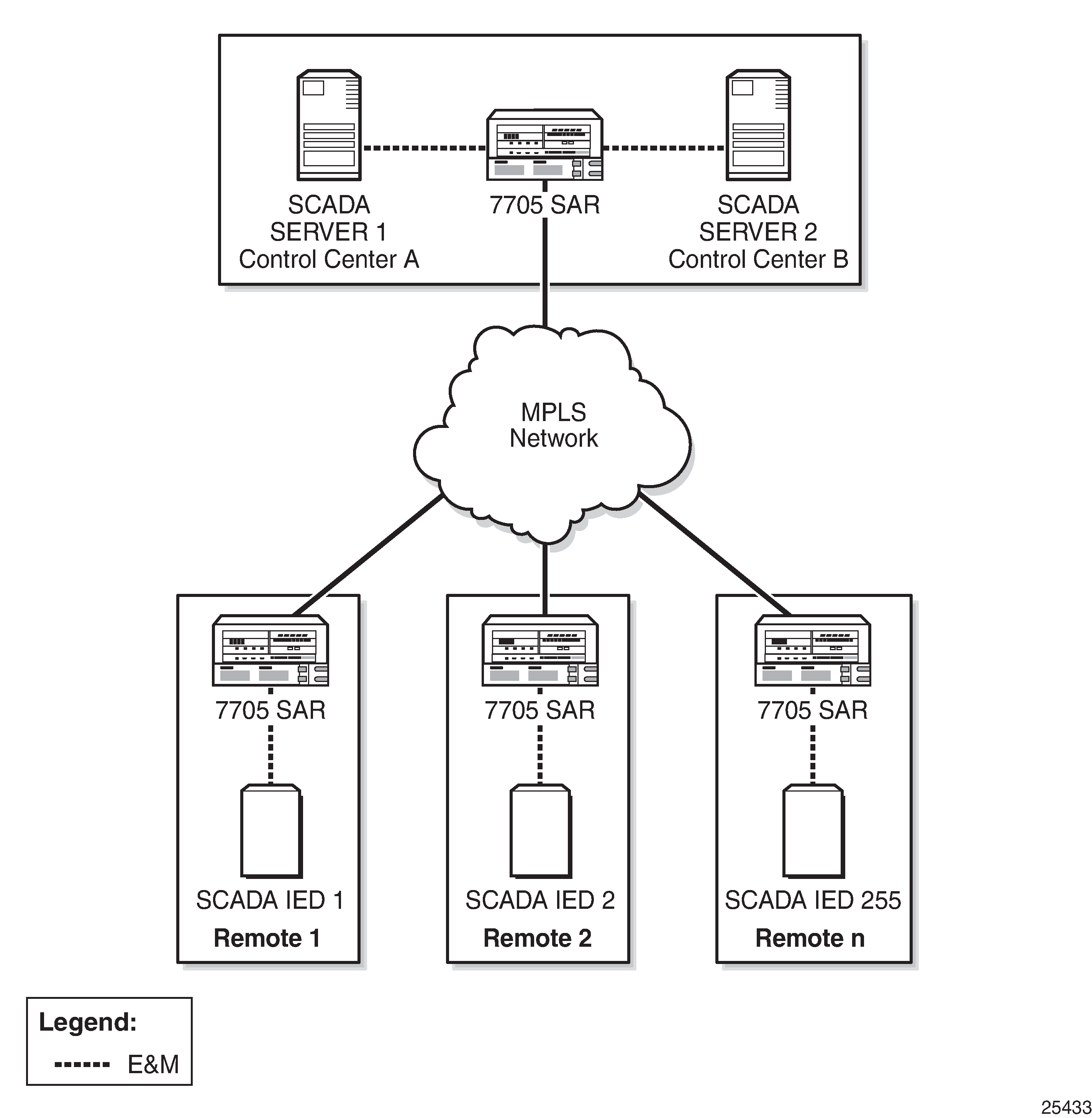
The pulse code modulation (PCM) multidrop bridge application provides multidrop bridging for SCADA systems that use 4-wire analog modems to connect remote slaves to a master. Incoming analog signals from the master are converted to PCM (Mu-Law or A-Law) for transport between a remote slave and the master. The Integrated Services card broadcasts the master stream to all remote slaves. Only the addressed remote unit will respond to the broadcast and the response must be transported through the bridge back to the master via an E&M interface. If the network RTUs support two SCADA systems over the same interface by separating them into high-frequency and low-frequency bands, the PCM multidrop bridge always selects the two loudest branches to be passed through the bridge for communication with the master.
E&M signaling transport through the bridge is not supported.
Figure: SCADA PCM Multidrop Bridge Network shows a typical SCADA PCM multidrop bridge network.

The PCM multidrop bridge application uses Mu-Law and A-Law encoding; therefore, the modularity is different from MDDB modularity. Table: PCM Multidrop Bridge Modularity shows the modularity for a PCM multidrop bridge on the Integrated Services card.
Encoding Scheme |
Number of Bridges per Integrated Services Card |
Number of Branches per Bridge |
Total Number of Branches per Integrated Services Card |
|---|---|---|---|
Mu-Law (North America) |
16 |
22 |
352 |
A-Law (rest of world) |
16 |
30 |
480 |
A PCM SCADA bridge is created using the config>scada bridge-id command and a branch is created using the config>scada>branch branch-id command.
Larger bridges can be built by cascading individual bridges internally within a single Integrated Services card and using the master output from one bridge as the slave input to another bridge. Larger bridges can be cascaded across multiple Integrated Services cards by using an E&M link.