3. Services Overview
3.1. In This Chapter
This chapter provides an overview of the 7705 SAR subscriber services, service model, and service entities. Additional details on the individual subscriber services are found in subsequent chapters.
Topics in this chapter include:
3.2. Introduction to Services on the 7705 SAR
Topics in this section include:
3.2.1. Overview
A service is a type of telecommunications connection from one place to another. These telecommunications connections have the particular attributes and characteristics that are needed to provide a specific communications link through which an information flow or exchange can occur. The 7705 Service Access Router (7705 SAR) offers VLL services, Layer 2 multipoint VPN services (VPLS), Layer 3 MPLS VPN services (VPRN), and Layer 3 routed/IP services.
The 7705 SAR service model uses (logical) service entities to construct a service. These logical entities provide a uniform, service-centric configuration, management, and billing model for service provisioning (see Nokia Service Model for more information). Many services can be created on the same 7705 SAR at the same time, and each service is uniquely identified by a service ID.
The 7705 SAR offers Virtual Leased Line (VLL) services (also referred to as pseudowire (PW) services or pipes), which emulate a Layer 1/2 entity, such as a wire or a leased line. These emulated services provide connectivity between a service access point (SAP) on one 7705 SAR and on another SAP on the same router, or on a remote 7705 SAR, 7710 SR, or 7750 SR. VLL services offer SAP logical entities—such as a VLAN or a virtual connection—Layer 2 visibility or processing (IMA termination). A SAP is the point where customer traffic enters and exits the service.
A connection between two SAPs on the same router is known as a local service. A connection between SAPs on a local and a remote router is known as a distributed service. SAP-to-SAP connections are supported for ATM, Ethernet, FR, HDLC, and TDM VLLs.
The 7705 SAR also supports the aggregation of multiple ATM VCC SAPs into a single aggregation group within a service. Aggregation groups enable service providers to make more efficient use of the ATM VCC VLL services that are deployed in a network.
Distributed services use service destination points (SDPs) to direct traffic from a local router to a remote router through a service tunnel. An SDP is created on the local router and identifies the endpoint of a logical unidirectional service tunnel. Traffic enters the tunnel at the SDP on the local router and exits the tunnel at the remote router. Hence, a service tunnel provides a path from a 7705 SAR to another service router, such as another 7705 SAR, a 7710 SR, or a 7750 SR. Because an SDP is unidirectional, two service tunnels are needed for bidirectional communication between two service routers (one SDP on each router).
SDPs are configured on each participating 7705 SAR or service router, specifying the address of the source router (the 7705 SAR participating in the service communication) and the address of the destination router, such as another 7705 SAR or service router. After SDPs are created, they are bound to a specific service. The binding process is needed to associate the far-end devices to the service; otherwise, far-end devices are not able to participate in the service.
The 7705 SAR also offers IES, VPLS, and VPRN services.
IES provides IP connectivity between customer access points. From the customer’s perspective, IES provides direct IP connectivity. The customer is assigned an IP interface and a SAP designates the customer access point where the customer IP device is connected—one SAP binding per IP interface. Supported SAP encapsulations are MC-MLPPP, PPP/MLPPP and null/dot1q/qinq Ethernet. SDP binding is not required because traffic is routed rather than being encapsulated in a tunnel.
A Virtual Private Routed Network (VPRN) consists of a set of customer sites connected to one or more PE routers. VPRNs are based on RFC 2547bis, which details a method of distributing routing information and forwarding data to provide a Layer 3 Virtual Private Network (VPN) service to end customers. VPRN traffic is transported over LDP and RSVP-TE tunnels, as well as static LSPs.
A Virtual Private LAN Service (VPLS) enables Layer 2 multipoint connections within an enterprise infrastructure. Supported SAP encapsulations are null/dot1q/qinq Ethernet (on the 8-port Ethernet Adapter card, 6-port Ethernet 10Gbps Adapter card, 7705 SAR-X, 8-port Gigabit Ethernet Adapter card, and the 10-port 1GigE/1-port 10GigE X-Adapter card) and ATM (on the 4-port OC3/STM1 Clear Channel Adapter card).
Note:
|
VPLS traffic can also be transported over existing tunnel types like GRE tunnels, LDP tunnels, RSVP-TE tunnels, and static LSPs using SDPs. For the ATM SAPs, the Layer 2 Ethernet frames are encapsulated in llc-snap bridged PDUs, as per RFC 2684, widely referred to with the obsoleted RFC 1483.
3.2.2. Service Types
Services are commonly called customer or subscriber services. The 7705 SAR offers the following types of services, which are described in more detail in the referenced chapters:
- Virtual Leased Line (VLL) services
- ATM VLL (Apipe)—a pseudowire emulation edge-to-edge (PWE3) ATM service over MPLS, GRE, or IP tunnels on 7705 SAR nodes. See ATM VLL (Apipe) Services.
- Circuit emulation VLL (Cpipe)—a PWE3 circuit emulation service over MPLS or GRE tunnels on 7705 SAR nodes. See Circuit Emulation VLL (Cpipe) Services.
- Ethernet VLL (Epipe)—a PWE3 Ethernet service over MPLS or GRE tunnels for Ethernet frames on 7705 SAR nodes. See Ethernet VLL (Epipe) Services.
- FR VLL (Fpipe)—a PWE3 FR service over MPLS or GRE tunnels for FR frames on 7705 SAR nodes. See Frame Relay VLL (Fpipe) Services.
- HDLC VLL (Hpipe)—a PWE3 HDLC service over MPLS or GRE tunnels for HDLC frames on 7705 SAR nodes. See HDLC VLL (Hpipe) Services.
- IP interworking VLL (Ipipe)—a PWE3 IP service between two hosts connected by any combination of point-to-point access circuits. IP interworking VLLs can operate over MPLS or GRE networks. Some typical examples are Ethernet SAP to Ethernet SAP, Ethernet SAP to MLPPP SAP, Ethernet SAP to LAG SAP, FR SAP to Ethernet SAP, or cHDLC SAP to Ethernet SAP. See IP Interworking VLL (Ipipe) Services.
- Internet Enhanced Service (IES)
- IES is used both as a direct Internet access service where the customer is assigned an IP interface for routed connectivity and for in-band management of the 7705 SAR. See Internet Enhanced Service.
- Virtual Private LAN Service (VPLS)
- VPLS provides a Layer 2 multipoint VPN service to end customers. VPLS includes Hierarchical VPLS (H-VPLS), which is an enhancement of VPLS that extends pseudowire-style signaled or static virtual circuit labeling outside the fully meshed VPLS core. The 7705 SAR can participate in hierarchical VPLS. In addition, the 7705 SAR supports management VPLS (mVPLS) via Rapid Spanning Tree Protocol (RSTP). See VPLS.
- Virtual Private Routed Network Service (VPRN)
- VPRN provides a Layer 3 VPN service to end customers. VPRN services provide MP-BGP peering with other PEs, configurable QoS policy and filtering, VRF import and export policies, and SGT-QoS marking. See VPRN Services.
Table 2 lists the supported pseudowire (PW) service types. The values are as defined in RFC 4446.
Table 2: Pseudowire Service Types
PW Service Type (Ethertype) | Value |
IP Layer 2 transport | 0x000B |
Ethernet tagged mode | 0x0004 |
Ethernet raw | 0x0005 |
HDLC | 0x0006 |
ATM N-to-one VCC cell mode 1 | 0x0009 |
ATM N-to-one VPC cell mode | 0x000A |
ATM transparent cell transport mode | 0x0003 |
SAToP E1 | 0x0011 |
SAToP T1 | 0x0012 |
CESoPSN basic mode | 0x0015 |
CESoPSN TDM with CAS | 0x0017 |
FR DLCI | 0x0019 |
- “N-to-one” is expressed as “N-to-1” throughout this guide.
Note:
3.2.3. Service Policies
Common to all 7705 SAR connectivity services are policies that are assigned to the service. Policies are defined at the global level, then applied to a service on the router. Policies are used to define 7705 SAR service enhancements.
The types of policies that are common to all 7705 SAR connectivity services are SAP Quality of Service (QoS) policies and accounting policies. Filter policies are supported on network interfaces, Epipes, Ipipes, VPLS SAPs and SDPs (mesh and spoke), VPRN SAPs and spoke SDPs, IES SAPs and spoke SDPs, and IES in-band management SAPs.
- SAP Quality of Service (QoS) policies allow for different classes of traffic within a service at SAP ingress and SAP egress.QoS ingress and egress policies determine the QoS characteristics for a SAP. A QoS policy applied to a SAP specifies the number of queues, queue characteristics (such as forwarding class, committed information rates, and peak information rates) and the mapping of traffic to a forwarding class. A QoS policy must be created before it can be applied to a SAP. A single ingress and a single egress QoS policy can be associated with a SAP.QoS ingress and egress policies also apply to SAP aggregation groups.
- Accounting policies define how to count the traffic usage for a service for billing purposes.The 7705 SAR routers provide a comprehensive set of service-related counters. Accounting data can be collected on a per-service, per-forwarding class basis, which enables network operators to accurately measure network usage and bill each customer for each individual service using any of a number of different billing models.
- Filter policies, also referred to as access control lists (ACLs), allow selective blocking or forwarding of traffic that matches criteria that is set in the policy. The resulting action (block or forward) is applied to that traffic.Filter policies control the traffic allowed into a SAP or SDP, and are based on IP or MAC match criteria. The ability to configure and apply a filter depends on the combination of service, traffic type and direction, and entity type (SAP or SDP). Assigning a filter policy to a SAP or SDP is optional. Filter policies are identified by a unique filter policy ID. A filter policy must be created before it can be applied. A single ingress and a single egress filter policy can be assigned to a SAP (if supported), and a single ingress filter policy can be assigned to an SDP (if supported).
For more information on provisioning QoS policies, including queuing behaviors, refer to the 7705 SAR Quality of Service Guide. For information on configuring IP and MAC filter policies, refer to the 7705 SAR Router Configuration Guide.
3.3. Nokia Service Model
The 7705 SAR routers are deployed at the provider edge (PE). Services are provisioned on the 7705 SAR and other network equipment in order to facilitate the transport of telecommunications data across an IP/MPLS provider’s core network. The data is formatted so that it can be transported in encapsulation tunnels created using generic routing encapsulation (GRE), IP encapsulation, or MPLS label switched paths (LSPs).
The service model has four main logical components, referred to as (logical) service entities. The entities are: customers, service types, service access points (SAPs), and service destination points (SDPs) (see Service Entities). In accordance with the service model, the operator uses the (logical) service entities to construct an end-to-end service. The service entities are designed to provide a uniform, service-centric model for service provisioning. This service-centric design implies the following characteristics.
- Many services can be bound to a single customer.
- Many services can be bound to a single tunnel.
- Tunnel configurations are independent of the services they carry.
- Changes are made to a single service entity rather than to multiple ports on multiple devices. It is easier to change one tunnel rather than several services.
- The operational integrity of a service entity (such as a service tunnel or service endpoint) can be verified by one operation rather than through the verification of dozens of parameters, thereby simplifying management operations, network scalability, and performance.
- A failure in the network core can be correlated to specific subscribers and services.
- The following policies are applied to various services:
- QoS policies
- accounting policies
- filter policies (IP and MAC)
Additional properties can be configured for bandwidth assignments, class of service, and accounting and billing on the appropriate entity.
3.4. Service Entities
The basic (logical) service entities in the service model used to construct an end-to-end service are:
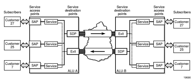
Figure 1 shows an example of how the service entities relate to the service model. A subscriber (or customer) attachment circuit connects to a SAP. SDPs define the entrance and exit points of unidirectional service tunnels, which carry one-way traffic between the two routers (ALU-A and ALU-B). After SDPs have been configured, they are bound to a service, which is the final step in making the end-to-end service connection. In Figure 1, the entrance point is labeled SDP and the exit point is labeled Exit.
Traffic encapsulation occurs at the SAP and SDP. The SAP encapsulation types are SONET/SDH, Ethernet, and TDM. The SDP encapsulation types are MPLS, GRE, and IP. For information on SAP encapsulation types, see SAP Encapsulation Types and Identifiers. For information on SDP encapsulation types, see SDP Encapsulation Types.
Figure 1: Service Entities and the Service Model
3.4.1. Customers
The terms customers and subscribers are used synonymously. Every customer account must have a customer ID, which is assigned when the customer account is created. To provision a service, a customer ID must be associated with the service at the time of service creation.
3.4.2. Service Types
Service types provide the traffic adaptation needed by customer attachment circuits (ACs). This (logical) service entity adapts customer traffic to service tunnel requirements. The 7705 SAR provides six types of VLL service (that is, point-to-point MPLS-based emulation service, also called Virtual Private Wire Service (VPWS)):
- ATM VLL (Apipe)
- circuit emulation VLL (Cpipe)
- Ethernet VLL (Epipe)
- Frame relay VLL (Fpipe)
- HDLC VLL (Hpipe)
- IP interworking VLL (Ipipe)
The 7705 SAR also provides Ethernet layer (MAC-based) VPLS service (including management VPLS), as well as IP layer VPRN and IES services, that offer any-to-any connectivity within a Virtual Routing Domain or Generic Routing Domain, respectively.
3.4.2.1. Service Names
A service ID number must be associated with a service at the time of service creation. Once the service is created, an optional service name can be assigned to the service for use by commands that reference the service.
3.4.3. Service Access Points (SAPs)
A service access point (SAP) is the point at which a service begins (ingress) or ends (egress) and represents the access point associated with a service. A SAP may be a physical port or a logical entity within a physical port. For example, a SAP may be a channel group within a DS1 or E1 frame, an ATM endpoint, an Ethernet port, or a VLAN that is identified by an Ethernet port and a VLAN tag. Each subscriber service connection on the 7705 SAR is configured to use only one SAP.
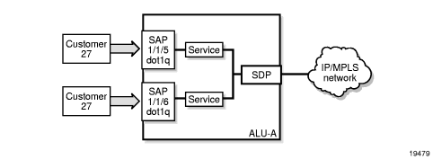
A SAP identifies the customer interface point for a service on a 7705 SAR router. Figure 2 shows one customer connected to two services via two SAPs. The SAP identifiers are 1/1/5 and 1/1/6, which represent the physical ports associated with these SAPs. The physical port information should be configured prior to provisioning a service. Refer to the 7705 SAR Interface Configuration Guide for more information about configuring a port. See Port and SAP CLI Identifiers for more information about identifiers.
The 7705 SAR supports the following services types: ATM pseudowires (Apipe), TDM pseudowires (Cpipe), IP pseudowires (Ipipe), Ethernet pseudowires (Epipe), FR pseudowires (Fpipe), HDLC pseudowires (Hpipe), IES, VPLS, and VPRN services. Customer access to these services is provided via SAPs. For each service type, the SAP has slightly different parameters.
In general, SAPs are logical endpoints that are local to the 7705 SAR and are uniquely identified by:
- the physical Ethernet port, SONET/SDH port, or TDM channel group
- the encapsulation type for the service (for example, ATM)
- the encapsulation identifier (ID), which is, for example, the optional VLAN ID for Epipes, or the channel group ID for Cpipes
Depending on the encapsulation, a physical port or channel can have more than one SAP associated with it (for example, a port may have several circuit groups, where each group has an associated SAP). SAPs can only be created on ports or channels designated as “access” in the physical port configuration.
SAPs cannot be created on ports designated as core-facing “network” ports because these ports have a different set of features enabled in software.
Figure 2: Service Access Point (SAP)
3.4.3.1. SAP Encapsulation Types and Identifiers
The SAP encapsulation type is an access property of the Ethernet port, SONET/SDH port, or TDM channel group used for the service. It identifies the protocol that is used to provide the service.
The 7705 SAR supports three SAP encapsulation types:
Encapsulation types may have more than one option to choose from. For example, the options for TDM encapsulation type include “cem” (for circuit emulation service) and “atm” (for ATM service), among others.
In the case of SAPs configured on the 16-port T1/E1 ASAP Adapter card version 2, the 32-port T1/E1 ASAP Adapter card, and the 4-port DS3/E3 Adapter card, the cards must be configured to support the appropriate encapsulation methods before the encapsulation type can be configured. This is done using the mda-mode command. Refer to the 7705 SAR Interface Configuration Guide for more information.
The encapsulation ID is an optional suffix that is appended to a port-id to specify a logical sub-element for a SAP. For example, port-id:qtag1 represents a port that can be tagged to use IEEE 802.1Q encapsulation (referred to as dot1q), where each individual tag can identify with an individual service. Similarly, port-id.channel-group:vpi/vci represents the encapsulation ID for an ATM SAP, which is a special case because it requires that a channel group identifier (which always uses the value 1) precede the VPI/VCI value.
Note:
|
3.4.3.1.1. Ethernet Encapsulations
The following encapsulation service options are available on Ethernet ports:
- null—supports a single service on the port; for example, where a single customer with a single service customer edge (CE) device is attached to the port.
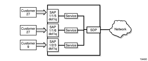
- dot1q—supports multiple services for one customer or services for multiple customers (see Figure 3). An example of dot1q use might be the case where the Ethernet port is connected to a multi-tenant unit device with multiple downstream customers. The encapsulation ID used to distinguish an individual service is the VLAN ID in the IEEE 802.1Q header.
- qinq— supports multiple services for one customer or services for multiple customers. The encapsulation IDs used to distinguish an individual service are the QinQ VLAN IDs in the IEEE 802.1ad header, producing a double-tagged frame. For more information on QinQ, see QinQ Support.
Figure 3: Multiple SAPs on a Single Port/Channel
3.4.3.1.1.1. Default SAP on a Dot1q and QinQ Port
The 7705 SAR supports default SAP functionality on dot1q- and qinq-encapsulated ports. On dot1q- and qinq-encapsulated ports where a default SAP is configured, all packets with Q-tags not matching any other explicitly defined SAPs are assigned to the default SAP for transport.
A default SAP is identified in the CLI by the use of the character “*” as a Q-tag, where the “*” means “all”. For example, port-id:vlan-x.* and port-id:*.* are default SAPs. The former case (vlan-x.*) is a specific example of the latter case (*.*), where the outer tag (vlan-x) matches an existing SAP VLAN ID. See Special QinQ SAP Identifiers for more information.
| Note: On the 7705 SAR, the *.* notation for QinQ behaves in the same way as the * notation for Dot1q. This behavior is different from the 7750 SR implementation. On the 7750 SR, the “*.*” notation is used only for VPLS service as a capture SAP. |
One of the applications where the default SAP feature can be used is for an access connection of a customer who uses the whole port to access Layer 2 services. The internal VLAN tags are transparent to the service provider. This (the use of a whole port) can be provided by a null-encapsulated port. A dedicated VLAN (not used by the user) can be used to provide CPE management.
In this type of environment, two SAPs logically exist, a management SAP and a service SAP. The management SAP can be created by specifying a VLAN tag that is reserved to manage the CPE. The service SAP covers all other VLANs and behaves as a SAP on a null-encapsulated port.
There are a few constraints related to the use of a default SAP on a dot1q- or a qinq-encapsulated port:
- The default SAP is supported only on VPLS and Epipe services and cannot be created in IES and VPRN services because IES and VPRN services cannot preserve VLAN tag markings.
- For VPLS SAPs with STP enabled, STP listens to untagged and null-tagged BPDUs only. All other tagged BPDUs are forwarded like other customer packets. This is the same behavior as null-encapsulated ports.
- IGMP snooping is not supported on a default SAP. By not allowing IGMP snooping of a default SAP, all IGMP packets will be transparently forwarded.
- The default SAP and the SAP defined by explicit null encapsulation are mutually exclusive (for example, 1/1/1:* and 1/1/1:0 are mutually exclusive, and 1/1/2:1.* and 1/1/2:1.0 are mutually exclusive). This avoids conflict as to which SAP untagged frames should be associated with.
3.4.3.1.2. SONET/SDH Encapsulations
The following service encapsulation option is available on SONET/SDH ports:
- atm—supports multiple service instances for one customer, as well as bridged llc-snap encapsulated ATM SAP termination to VPLS
3.4.3.1.3. TDM and Serial (TDM) Encapsulations
The following service encapsulation options are available on TDM and SDI ports:
- atm—supports multiple services for one customer (TDM ports only)
- cem—supports multiple services for one customer. Structured cem service (circuit emulation service over packet switched network (CESoPSN (n × DS0)) and unstructured cem service (structure-agnostic TDM over packet (SAToP)) are supported. (TDM and SDI ports)
- ipcp—supports a single IP service per TDM channel group on channelized interfaces. This is typically used for router interconnection using the point-to-point protocol (PPP). (TDM ports, and SDI V.35 and X.21 ports at super-rate speeds)
- frame-relay (TDM ports, and SDI V.35 and X.21 ports at super-rate speeds)
- cisco-hdlc (TDM on DS1/E1 ports, and SDI V.35 and X.21 ports at super-rate speeds)
- hdlc (TDM on DS1/E1 ports, and SDI V.35 and X.21 ports at super-rate speeds)
3.4.3.1.4. Service Types and SAP Encapsulations—Summary
Table 3 lists the SAP encapsulations available to 7705 SAR service types. These encapsulations apply to access-facing ports. The service (port) type and encapsulations are configured at the port level. See the 7705 SAR Interface Configuration Guide for more information about the cards and ports that support each of the service types.
Table 3: Service Types and SAP Encapsulations
Service (Port) Type | Encapsulation Option |
Ethernet | null |
Ethernet | dot1q |
Ethernet | qinq |
SONET/SDH | atm |
TDM | cem |
TDM | atm |
TDM | ipcp |
TDM | frame-relay |
TDM | cisco-hdlc |
TDM | hdlc |
3.4.3.2. SAP Configuration Considerations
In addition to being an entry or exit point for service traffic, a SAP has to be configured for a service and, therefore, has properties. When configuring a SAP, consider the following.
- A SAP is a local entity and is only locally unique to a given device. The same SAP ID value can be used on another 7705 SAR.
- There are no default SAPs. All subscriber service SAPs must be created.
- The default administrative state for a SAP at creation time is administratively enabled.
- When a SAP is deleted, all configuration parameters for the SAP are also deleted.
- A SAP is owned by and associated with the service in which it is created.
- An Ethernet port or channel with a dot1q encapsulation type means that the traffic for the SAP is identified based on a specific IEEE 802.1Q VLAN ID value. The VLAN ID is stripped off at SAP ingress and the appropriate VLAN ID is placed on at SAP egress. As a result, VLAN IDs only have local significance, so the VLAN IDs for the SAPs for a service need not be the same at each SAP. QinQ encapsulation means that the SAP is identified based on specific IEEE 802.1ad VLAN ID values.
- A TDM circuit emulation service (for example, CESoPSN) requires a channel group. The channel group must be created before it can be assigned to a SAP.
- An ATM service (for example, ATM N-to-1 VCC cell transport) on a 16-port T1/E1 ASAP Adapter card, 2-port OC3/STM1 Channelized Adapter card, or a 4-port OC3/STM1 / 1-port OC12/STM4 Adapter card requires a channel group. For this case, the channel group requires the assignment of all 24 timeslots (T1) or 30 timeslots (E1). The timeslot assignments are made automatically after a channel group is configured for ATM encapsulation.
- If a port or channel is administratively shut down, all SAPs on that port or channel will be operationally out of service.
- A SAP cannot be deleted until it has been administratively disabled (shut down).
- Each SAP can have one of the following policies assigned to it:
- Ingress QoS policy
- Egress QoS policy
- Accounting policy
- Ingress filter policy (for Epipe SAPs, Ipipe SAPs, VPLS SAPs, VPRN SAPs, IES SAPs, and IES in-band management SAPs)
- Egress filter policy (for VPRN and IES SAPs, and for VPLS SAPs (Ethernet SAPs only))
3.4.4. Service Destination Points (SDPs)
An SDP identifies the endpoint of a logical unidirectional service tunnel. The service tunnel provides a path from one 7705 SAR to another network device, such as another 7705 SAR, a 7710 SR, or a 7750 SR.
In more general terms, SDP refers to the service tunnel itself. The SDP terminates at the far-end router, which is responsible for directing the flow of packets to the correct service egress SAPs on that device.
| Note: In this document and in command line interface (CLI) usage, SDP is defined as Service Destination Point. However, it is not uncommon to find the term SDP defined in several different ways, as in the following list. All variations of SDP have the same meaning:
|
When an SDP is bound to a service, the service is referred to as a distributed service. A distributed service consists of a configuration with at least one SAP on a local node, one SAP on a remote node, and an SDP binding that binds the service to the service tunnel.
An SDP has the following characteristics.
- An SDP is locally unique to a participating 7705 SAR. The same SDP ID can appear on other 7705 SAR routers.
- An SDP uses the system IP address of the far-end edge router to locate its destination.
- An SDP is not specific to any one service or to any type of service. Once an SDP is created, services are bound to the SDP. An SDP can also have more than one service type associated with it.
- All services bound to an SDP use the same SDP (transport) encapsulation type defined for the SDP (GRE, IP, or MPLS).
- An SDP is a service entity used for service management. Even though the SDP configuration and the services carried within it are independent, they are related objects. Operations on the SDP affect all the services associated with the SDP. For example, the operational and administrative state of an SDP controls the state of services bound to the SDP.
- An SDP tunnel from the local device (typically, a 7705 SAR) to the far-end device (router) requires a return SDP tunnel from the far end back to the local device. Each device must have an SDP defined for every remote router to which it wants to provide service. The SDP must be created before a distributed service can be configured.
- An SDP can be used to provide PW redundancy, where up to four spoke SDPs can be assigned to a service endpoint that acts as the managing entity to ensure service connection. See Pseudowire Redundancy.
3.4.4.1. SDP Binding
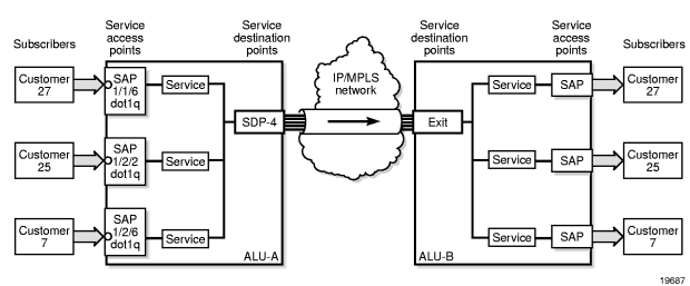
To configure a distributed service pointing from ALU-A to ALU-B, the SDP ID on the ALU-A side (see Figure 4) must be specified during service creation in order to bind the service to the tunnel (the SDP). Otherwise, service traffic is not directed to a far-end point and the far-end 7705 SAR devices cannot participate in the service (there is no service). To configure a distributed service pointing from ALU-B to ALU-A, the SDP ID on the ALU-B side must be specified.
Figure 4: SDP Tunnel Pointing from ALU-A to ALU-B
3.4.4.2. Spoke and Mesh SDPs
There are two types of SDPs: spoke and mesh. The type of SDP defines how flooded traffic (or broadcast traffic, such as an ARP request) is propagated. For point-to-point PW/VLL services, spoke SDPs are the only way to bind services to the far-end router. For VPLS, mesh and spoke SDP bindings are allowed.
A spoke SDP that is bound to a service operates like a traditional bridge port. Flooded traffic that is received on the spoke SDP is transmitted to all the spoke SDPs, mesh SDPs, and SAPs to which it is connected. Flooded traffic is not transmitted back toward the port from which it was received.
In contrast, a mesh SDP that is bound to a service operates like a single bridge port. Flooded traffic received on a mesh SDP is transmitted to all spoke SDPs and SAPs to which it is connected. Flooded traffic is not transmitted to any other mesh SDPs or back toward the port from which it was received. This property of mesh SDPs is important for multi-node networks; mesh SDPs are used to prevent the creation of routing loops.
3.4.4.3. SDPs and BGP Route Tunnels
SDP can use BGP route tunnels to extend inter-AS support for Layer 2 and Layer 3 VPN services as defined in RFC 3107. An SDP can be configured based on service transport method (for example, GRE or MPLS tunnel). MPLS SDP support is enhanced to allow a BGP route tunnel to reach the far-end PE.
A single method of tunneling is allowed per SDP (for example, LDP LSP, RSVP-TE LSP or BGP route tunnel).
For an inter-AS far-end PE, the next hop for the BGP route tunnel must be one of the local ASBRs. The LSP type selected to reach the local ASBR (BGP-labeled route next hop) must be configured under the BGP global context. LDP/RSVP must be supported to provide a transport LSP to reach the BGP route tunnel next hop.
Only BGP route labels can be used to transition from an ASBR to the next-hop ASBR. The global BGP route tunnel transport configuration option must be configured to select an LSP to reach the PE node from the ASBR.
For more information on BGP route tunnels, refer to the 7705 SAR Routing Protocols Guide, “BGP Route Tunnels”.
3.4.4.4. SDP Encapsulation Types
The Nokia service model uses encapsulation tunnels (also referred to as service tunnels) through the core to interconnect 7705 SAR and SR routers. An SDP is a logical way of referencing the entrance to an encapsulation tunnel.
The following encapsulation types are supported:
- Layer 2 within multiprotocol label switching (MPLS Encapsulation)
- Layer 2 or Layer 3 within generic routing encapsulation (GRE Encapsulation)
- Layer 2 within IP (IP Encapsulation)
Each SDP service tunnel has an entrance and an exit point for the pseudowires contained within it.
3.4.4.4.1. MPLS Encapsulation
Multiprotocol label switching (MPLS) encapsulation has the following characteristics.
- An MPLS 7705 SAR router supports both signaled and non-signaled LSPs through the network.
- Non-signaled paths are defined at each hop through the network.
An SDP has an implicit Maximum Transmission Unit (MTU) value because services are carried in encapsulation tunnels and an SDP is an entrance to the tunnel. The MTU is configurable (in octets), where the transmitted frame can be no larger than the MTU.
With MPLS, the MTU for the network port permits the addition of labels for transmission across the MPLS network. Ethernet frames that are sent out of a network port toward the MPLS core network (or a P router) are allowed to be oversized in order to include the MPLS labels without the need to fragment large frames. See MTU Settings for more information.
The following ways of configuring an MPLS tunnel are supported:
- LDP signaled
- RSVP-TE signaled
- user-configured (static LSP)
3.4.4.4.2. GRE Encapsulation
Generic routing encapsulation (GRE) is one of the most common tunneling techniques in the industry. GRE tunnels are used to transport various network layer packets and are especially useful for facilitating pseudowires over IP networks. Since MPLS is a Layer 2.5 protocol, MPLS packets cannot be natively transported over a Layer 3 (IP) network. Therefore, GRE is the ideal alternative for applications where traffic must travel over a Layer 3 network; for example, in DSL applications.
For the HSDPA offload application (see HSDPA Offload), ATM pseudowires are transported over IP using GRE tunneling. For other applications, Ethernet and TDM pseudowires over GRE are also supported.
GRE SDPs are supported on all network interfaces.
3.4.4.4.2.1. GRE Format
In accordance with RFC 2784, a GRE encapsulated packet has the following format:
- delivery header
- GRE header
- payload packet
Delivery Header
The delivery header is always an IP header.
GRE Header
The GRE header format is shown in Figure 5 and described in Table 4.
Figure 5: GRE Header

Table 4: GRE Header Descriptions
Field | Description |
C | Specifies whether there is a checksum in the header If set to 1, both the checksum and reserved1 fields must be present On the 7705 SAR, in the network egress (transmit) direction, the C bit is always set to 0; therefore, the checksum and reserved1 fields are omitted from the header. The GRE header is therefore always 4 bytes (32 bits) in the network egress direction. In the network ingress direction, the C bit validity is checked. If it is set to a non-zero value, the GRE packet is discarded and the IP discards counter is increased. |
Reserved0 | Indicates whether the header contains optional fields Not applicable to the 7705 SAR—first 5 bits of the field are always set to 0 and bits 6 to 12 are reserved for future use and also set to 0 by the 7705 SAR |
Ver | Always set to 000 for GRE At network ingress, if a GRE packet is received with the version field set to any value other than 000, the packet is discarded and the IP discards counter is increased |
Protocol Type | Specifies the protocol type of the original payload packet—identical to Ethertype with the only supported option being MPLS unicast (0x8847) |
Checksum (optional) | Not applicable |
Reserved1 (optional) | Not applicable |
Payload Packet
The payload encapsulation format for pseudowires over GRE is shown in Figure 6 and described in Table 5.
Figure 6: GRE Pseudowire Payload Packet over Ethernet

Table 5: GRE Pseudowire Payload Packet Descriptions
Field | Description |
Eth | The Layer 2 transport header The only Layer 2 protocol supported is Ethernet MTU size depends on the encapsulation type (14 bytes for null encapsulation, 18 bytes for dot1q encapsulation, and 22 bytes for qinq encapsulation) |
IP | Indicates the transport protocol The Ethertype is always set to IP (0x800), and in case of a mismatch, the unexpected or illegal Ethertype counters are increased 1 |
GRE | Indicates the encapsulation protocol |
PW header | The pseudowire header identifies a service within the GRE tunnel |
CW (optional) | The pseudowire control word (CW) is a 32-bit (4-byte) field that is inserted between the VC label and the Layer 2 frame For more information on the control word, see Pseudowire Control Word |
PW payload | The PW payload is the payload of the service being encapsulated (Ethernet, ATM, or TDM) |
- The only exception to the Ethertype is if the packets are address resolution protocol (ARP) packets. For information on ARP, refer to the 7705 SAR Router Configuration Guide.
Note:
At the network egress of the 7705 SAR, the source address of the IP header is always set to the system IP address. The destination IP address is set to the system IP address of the service router on which the GRE SDP is configured, the far-end interface address, or the loopback address. Using the system IP addresses to bring up the GRE session ensures that any IP link between the two routers can be used to transport GRE/IP packets. It might therefore be necessary to use static IP address configuration over DSL networks to ensure connectivity between the routers (especially if the DSL modem is in bridge mode).
3.4.4.4.2.2. GRE Fragmentation
IP fragmentation can be enabled for GRE tunnels. Services for which fragmentation is typically not available can make use of IP fragmentation performed at the IP layer of the GRE tunnel. The IP fragmentation feature can be enabled at the GRE tunnel ingress by enabling the allow-fragmentation command on the SDP. The IP fragmentation size limits are derived from the MTU of the network port used by the GRE tunnel.
At the GRE tunnel egress, IP reassembly can be performed as specified by a reassembly profile assigned to the network interfaces on which the GRE packets are expected to arrive. The IP reassembly function is performed on the IP fragments received at the GRE tunnel egress before any underlying service label is processed. A reassembly profile is used to specify the amount of buffer space allocated for the IP reassembly function and to configure a reassembly timeout. These parameters are configured for each forwarding class to isolate different types of GRE traffic.
When allow-fragmentation is enabled on an SDP, the current MTU algorithm is overwritten with the configured path MTU. The administrative MTU and operational MTU both show the specified MTU value. If the path MTU is not configured or available, the operational MTU is set to 2000 bytes, and the administrative MTU displays a value of 0. When allow-fragmentation is disabled, the operational MTU reverts to the previous value.
Fragmentation is supported on the following types of GRE SDPs:
- VPLS
- Layer 3 spoke SDP
- Epipe
IP packets that are transported over a Layer 3 spoke SDP using a fragmentation-enabled GRE tunnel are handled differently depending on the DF bit setting and the size of the packet.
- If the packet DF bit setting is 0 (Fragment), the GRE fragment size is determined by the network port MTU value.
- If the packet DF bit setting is 1 (Do not fragment), and the packet size is smaller or equal to the smaller value of either the operational MTU of the spoke SDP or the Layer 3 spoke SDP interface MTU (if configured), the packet is sent through the GRE tunnel and the fragment size is determined by either the network port MTU value or the Layer 3 spoke interface MTU value, whichever is smaller.
- If the packet DF bit setting is 1 (Do not fragment), and the packet size is larger than the smaller value of either the operational MTU of the spoke SDP or the Layer 3 spoke SDP interface MTU (if configured), the packet is discarded and an ICMP message “Fragmentation Needed and Don’t Fragment was Set” is sent back to the source IP address.
IP reassembly profiles are required to ensure that all packet fragments are received within an expected time frame for each forwarding class. When the reassembly profile timers expire, all fragments of the corresponding incomplete frame are dropped and a “Fragment Reassembly Time Exceeded” ICMP error message is sent to the source node.
| Note: The system checks the reassembly queues every 64 ms in a constant loop, which may cause a maximum of 63 ms variation between the user-configured value and the actual detection time. For example, using the default configuration of 2000 ms, the system may check the reassembly queue timer at 1999 ms, in which case the timeout would not occur during that cycle and would instead take place during the next cycle at 2063 ms. |
Traffic ingressing a GRE tunnel can use different forwarding classes and different queues. If multiple queues are transmitting fragments, a higher-priority queue could interrupt the transmission of fragments of a frame in a lower-priority queue by interleaving fragments of another frame. If the fragments from the different frames have similar IP identifiers, they could be reassembled incorrectly into one frame at the tunnel egress. To prevent this incorrect reassembly of frames, the 7705 SAR that is performing the IP fragmentation uses 4 bits of the 16-bit IP identifier to indicate the transmitting queue at the tunnel ingress. The IP identifier is part of the IP reassembly tuple, which also contains the protocol, source address, and destination address. Using the IP reassembly tuple, fragments of frames from different queues are always differentiated. However, reserving 4 bits in the IP identifier field leaves only 12 bits to act as a sequence number, which causes a shorter identifier wraparound. The time required for the IP identifier to wrap around is a function of the traffic rate on a given queue at the GRE tunnel ingress.
If fragments are dropped along the GRE tunnel due to congestion or bit errors, the 7705 SAR that is performing the IP reassembly at the tunnel egress normally drops partially reassembled packets due to expiration of the reassembly timeout interval. If fragment loss occurs in the network along with an IP identifier wraparound due to a high packet rate, the IP reassembly block may incorrectly insert fragments of a new frame into a frame of older fragments that are waiting for timeout. When configuring the timeout interval, it is therefore important to factor in the pre-fragmentation frame rate for forwarding classes on a GRE tunnel. As a guideline, higher-priority packets should have shorter timeout intervals than other packets because their queue interruption at the ingress GRE tunnel is minimal, and the timeout intervals should be shorter than the transmission time of 4096 packets for that forwarding class.
When the last fragment of a frame is received before the middle fragments, all fragments of the corresponding incomplete frame are dropped.
The 7705 SAR does not support double fragmentation.
3.4.4.4.3. IP Encapsulation
IP encapsulation is added to the 7705 SAR in response to a growing demand for more pseudowire-based solutions in mobile backhaul. IP encapsulation is similar to GRE encapsulation but allows pseudowires to be transported natively over IP packets. Only static pseudowires are supported for IP SDPs, because there is no label path to define except for the endpoints. The path is an IP routed path.
Since Release 3.0, the 7705 SAR has supported the transport of pseudowires over IP tunnels. All pseudowire types supported since Release 3.0 can be transported over IP tunnels. Figure 7 shows an example of an application using Apipes over IP over Ethernet.
3.4.4.4.3.1. Payload Packet
A typical payload encapsulation format for pseudowires over IP is shown in Figure 7 and described in Table 6.
Figure 7: IP Example of Pseudowire Payload Packet over Ethernet

Table 6: IP Pseudowire Payload Packet Descriptions
Field | Description |
Eth | The Layer 2 transport header The only Layer 2 protocol supported is Ethernet MTU size depends on the encapsulation type (14 bytes for null encapsulation, 18 bytes for dot1q encapsulation, and 22 bytes for qinq encapsulation) |
IP | Indicates the transport protocol The only supported option is MPLS in IP (0x89) The Ethertype is always set to IP (0x0800), and in case of a mismatch, the unexpected or illegal Ethertype counters are increased 1 |
PW header | The pseudowire header identifies a service within the IP tunnel. The pseudowire header is like an MPLS header that has context only to the encapsulating and decapsulating LERs. This means that the IP transport network has no knowledge about the pseudowires that it carries. Only the edge LERs are aware of the pseudowire because the IPv4 Protocol Number field is set to 137 (0x89), indicating an MPLS unicast packet. |
CW (optional) | The pseudowire control word (CW) is a 32-bit (4-byte) field that is inserted between the VC label and the Layer 2 frame For more information on control word, see Pseudowire Control Word |
ATM Cell #1 to ATM Cell #N | Indicates the payload of the service being encapsulated (ATM) |
- The only exception to the Ethertype is if the packets are address resolution protocol (ARP) packets. For information on ARP, refer to the 7705 SAR Router Configuration Guide.
Note:
3.4.4.5. Spoke SDP Terminations
The 7705 SAR supports spoke SDP as termination points for IES and VPRN services. Table 7 shows which service interfaces and spoke SDPs can be connected to each other. For example, an Epipe spoke SDP can connect to an IES or VPRN interface. Refer to Spoke SDP Termination to IES and to Spoke SDP Termination to VPRN for more information.
Table 7: Spoke SDP Termination Support
Epipe Spoke SDP | Epipe Spoke SDP Redundancy (standby-signal-master enabled) | IES Interface | VPRN Interface | VPLS Spoke SDP | VPLS Spoke SDP Redundancy (suppress-standby- signaling disabled) | |
Epipe Spoke SDP | ✓ | ✓ | ✓ | ✓ | ✓ | ✓ |
Epipe Spoke SDP Redundancy (standby-signal-master enabled) | ✓ | ✓ | ✓ | ✓ | ✓ | ✓ |
IES Interface | ✓ | ✓ | ✓ | ✓ | ✓ | ✓ |
VPRN Interface | ✓ | ✓ | ✓ | ✓ | ✓ | ✓ |
VPLS Spoke SDP | ✓ | ✓ | ✓ | ✓ | ✓ | ✓ |
VPLS Spoke SDP Redundancy (suppress-standby- signaling disabled) | ✓ | ✓ | ✓ | ✓ | ✓ | ✓ |
3.4.4.6. SDP Ping
Ping is an application that allows a user to test whether a particular host is reachable. SDP Ping is an application that allows a user to test whether a particular SDP endpoint is reachable.
SDP ping uses the SDP identifier that is stored in the 7705 SAR that originates the ping request. SDP ping responses can be configured to return through the corresponding return tunnel as a round-trip ping, or out-of band when unidirectional pings are requested. Refer to the 7705 SAR OAM and Diagnostics Guide, “SDP Ping”, for more information.
3.4.4.7. SDP Keepalives
The SDP keepalive application allows a system operator to actively monitor the SDP operational state using periodic Nokia SDP Echo Request and Echo Reply messages. Automatic SDP keepalives work in a manner that is similar to a manual SDP ping command. The SDP Echo Request and Echo Reply messages provide a mechanism for exchanging far-end SDP statuses.
SDP keepalive Echo Request messages are only sent after the SDP has been completely configured and is administratively up and the SDP keepalives are administratively up. If the SDP is administratively down, keepalives for the SDP are disabled.
SDP keepalive Echo Request messages are sent out periodically based on the configured Hello Time. An optional message length for the Echo Request can be configured.
The SDP is immediately brought operationally down when:
- the Max Drop Count Echo Request messages do not receive an Echo Reply
- a keepalive response is received that indicates an error condition
After a response is received that indicates the error has cleared and the Hold Down Time interval has expired, the SDP is eligible to be put into the operationally up state. If no other condition prevents the operational change, the SDP enters the operational state.
Configuring SDP keepalives on a given SDP is optional. SDP keepalives have the following configurable keepalive parameters:
- Hello Time
- Message Length
- Max Drop Count
- Hold Down Time
- Timeout
For information about configuring keepalive parameters, refer to Configuring an SDP.
3.5. Mobile Solutions
Topics in this section include:
The Mobile Radio Access Network (RAN) is rapidly growing to meet the increased demand in mobile services. This in turn increases demands on carriers to provide high-bandwidth, mobile broadband services. Today, at a typical cell site, 2G and 3G base stations are connected to high-cost, T1/E1 leased lines that are used to backhaul both voice and data traffic to the MTSO. For mission-critical, delay-sensitive, and low-bandwidth traffic such as voice, signaling, and synchronization traffic, it is vital that the high availability of these leased lines is ensured. SLA agreements also promise a high level of availability for customers.
Currently, however, best-effort traffic such as high-speed downlink packet access (HSDPA) is also switched over these SLA-enabled leased lines. HSDPA is a 3G mobile telephony communications service that allows UMTS networks to have higher data transfer speeds and capacity, allowing the mobile customer (end user) to browse the Internet or to use the mobile device. The increasing use of HSDPA is having a dramatic impact on the ability of the T1/E1 leased lines to scale with the traffic growth as well as on the operating costs of these lines.
Similar issues confront CDMA EVDO networks today.
Nokia provides a solution that enables mobile operators to keep their existing infrastructure (circuit-based leased lines), while gradually migrating to a packet-based infrastructure that will allow scalability, decrease costs, and ease the transition to the next-generation, all-IP network solutions.
3.5.1. HSDPA Offload
The Nokia solution is to make use of widely available DSL networks and split the traffic being backhauled. Mission-critical traffic (voice, signaling, synchronization) remains on the T1/E1 leased line circuits, while the best-effort, bandwidth-hungry HSDPA traffic is off-loaded to DSL networks.
The 7705 SAR-A and the 7705 SAR-M with DSL modules are ideal candidates for this scenario. They are small-scale versions of the 7705 SAR product family, optimized for use in standalone small or midsized sites where traffic aggregation from multiple cell sites is not needed. For more information on the 7705 SAR-A and the 7705 SAR-M, refer to the 7705 SAR-A Chassis Installation Guide and the 7705 SAR-M Chassis Installation Guide.
Figure 8 shows an example of HSDPA offload with the 7705 SAR-A.
Figure 8: 7705 SAR-A HSDPA Offload Example
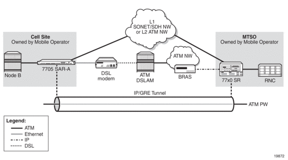
A 3G Node B is connected to a 7705 SAR over an ATM/IMA access port (SAP endpoint). An ATM SAP-to-SAP connection is set up in the 7705 SAR and a pseudowire is configured between the two endpoints to emulate local ATM switching. Traffic from the Node B enters an ATM/IMA port, the VCs transporting mission-critical traffic are locally switched (SAP-to-SAP) to another ATM/IMA port (SAP endpoint), and then switched over the leased lines to the MTSO.
| Note: ATM SAP-to-SAP connections are supported between any T1/E1 ASAP port that is in access mode with ATM/IMA encapsulation and another port with the same encapsulation configuration. One endpoint of a SAP connection can be an IMA group, while the other endpoint can be on a single ATM port. ATM SAP-to-SAP connections are also supported between any two OC3/STM1 ports and between any T1/E1 ASAP port and OC3/STM1 port, as long as both SAPs support ATM. |
For non-mission-critical traffic, for example, HSDPA traffic, an Ethernet interface on the 7705 SAR is connected to an external DSL modem. HSDPA traffic is interworked to ATM pseudowires and transported over the DSL network to the BRAS, then forwarded to the service router at the MTSO.
Figure 9 shows an example of HSDPA offload with the 7705 SAR-M using an 8-port xDSL module. Figure 10 shows an example of HSDPA offload with the 7705 SAR-M using a 6-port DSL Combination module.
Figure 9: 7705 SAR-M With 8-port xDSL Module for HSDPA Offload
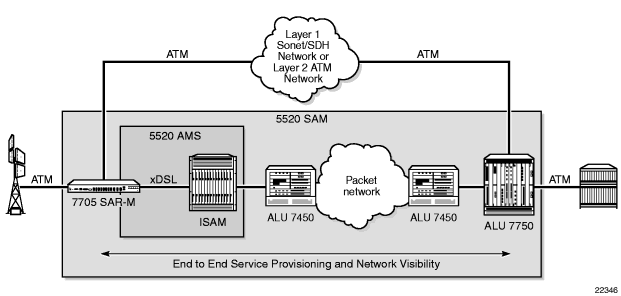
Figure 10: 7705 SAR-M With 6-port DSL Combination Module for HSDPA Offload

On a 7705 SAR-M with an 8-port xDSL module, non-real-time UMTS traffic is backhauled over the xDSL connection and all voice traffic remains on the existing attached TDM network. For this type of network, timing recovery via DSL is typically not required as synchronization can be derived from the attached TDM network.
On a 7705 SAR-M with a 6-port DSL Combination module, non-real-time UMTS traffic is backhauled over the xDSL connection and all voice traffic is backhauled over the SHDSL interface. Using SHDSL rather than existing ATM or TDM networks as the primary means to backhaul voice and signaling is an additional step toward improving the economies of backhaul. With this functionality, all voice, signaling, and HSDPA offload can be backhauled over a low-cost DSL network. The network characteristics of SHDSL are based on the design considerations for T1/E1 lines and are subject to lower latency and delay compared with xDSL. Clock recovery with NTR is supported over both SHDSL and xDSL interfaces on the 6-port DSL Combination module and over any xDSL interface on the 8-port xDSL module.
3.5.1.1. Failure Detection
Failure of the GRE SDP or the IP network it rides over can be detected by OAM tools as well as by BFD. With SAA, OAM tools can be configured to run periodically in order to facilitate faster failure detection. If a failure occurs, the ATM SAPs must be rerouted by the NSP NFM-P to the ATM ports used for backhauling the traffic. The mission-critical traffic is still serviced before the best-effort HSDPA traffic.
For information on OAM and SAA tools, refer to the 7705 SAR OAM and Diagnostics Guide. For information on BFD, refer to the 7705 SAR Router Configuration Guide.
3.5.2. Pure DSL Backhaul
There are two applications for pure backhaul over DSL:
- wholesale mobile backhaul aggregation or business services provided via DSL
- cell site aggregation from one or more base stations
Timing and/or synchronization are typically not requirements for deployments of the first application since mobile operators have their own cell site aggregator for timing recovery. Figure 11 shows a typical network using pure DSL backhaul with a 7705 SAR-M. Pure DSL backhaul is also supported on networks with distributed MPLS services.
Figure 11: Pure DSL Backhaul Network Example
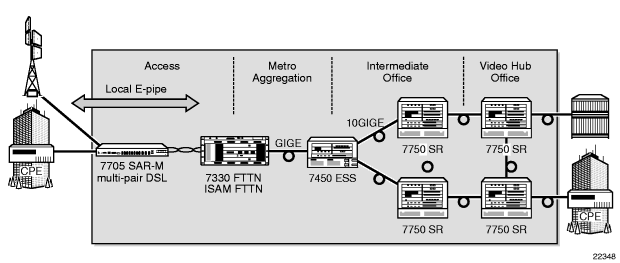
Figure 12 shows a breakdown of the traffic on this network.
Figure 12: DSL Network Traffic
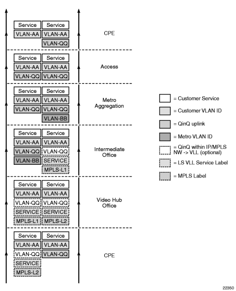
In the case of pure backhaul via DSL for a mobile operator, legacy 2G and 3G traffic is aggregated at the 7705 SAR-M then fed upstream to a connected ISAM. Services remain terminated on a 7750 SR as shown in Figure 11, but without the north ATM path. Timing recovery is provided by a local GPS at the cell site, by NTR, or by 1588 for frequency synchronization.
| Note: Using 1588 for timing recovery over DSL requires careful consideration of the end-to-end network characteristics for 1588v2 PTP delivery, and for the underlying PDV characteristics of the DSL used to transport the PTP packets. |
Pure DSL backhaul maximizes savings for mobile operators since leased lines are not used at all. SHDSL can also be more expensive to deploy and operate because it is generally not deployed for residential broadband services. Additionally, when mobile backhaul services are combined with triple-play services reusing the same broadband platform (in this case the ISAM), the pure DSL backhaul architecture offers a compelling, cost-effective solution across a wide range of scenarios.
The pure DSL backhaul deployment model may be Layer 2-based with the use of a local Epipe on the 7705 SAR-M as shown in Figure 11. The SAP facing the ISAM must support an Epipe SAP and an IES SAP for in-band management. Alternatively, distributed services via MPLS or GRE tunnels can be used with pure DSL backhaul to offer distributed VPLS, VPRN, IES, or VLL services.
3.5.2.1. DSL Channel Bonding
DSL channel bonding provides an ideal mix of features, including higher bandwidth for all users and the ability to extend the distance that can be reached at certain bandwidths. DSL bonding distributes traffic over a bundle of copper pairs instead of just a single copper pair. For example, to achieve an effective bandwidth of 12 Mb/s, three DSL lines of 4 Mb/s are bundled with a channel bonding processor at each of the Central Office and CPE devices.
In order to meet the growing needs of mobile backhaul and business services in areas where fiber connectivity is not available, DSL access solutions can be used as a viable alternative through the use of channel bonding for increased rate and reach. For more information about DSL bonding and DSL modules, see the 7705 SAR Interface Configuration Guide and the 7705 SAR-M Chassis Installation Guide.
3.6. ETH-CFM (802.1ag and Y.1731)
Topics in this section include:
Ethernet Connectivity Fault Management (ETH-CFM) is defined in two complementary standards: IEEE 802.1ag (dot1ag) and ITU-T Y.1731. Both standards specify protocols, procedures, and managed objects in support of transport fault management, including discovery and verification of the path, and detection and isolation of a connectivity fault for each Ethernet service instance.
Dot1ag and Y.1731 provide fault management (FM) functions for loopback, linktrace, and connectivity checks, as well as Up and Down MEP support for Ethernet SAPs, Down MEP support for spoke SDPs (dot1ag only), and facility MEP support for network interfaces.
Y.1731 fault management (Y.1731 FM) extends dot1ag CFM by providing functions for alarm indication signal (AIS) and ETH-Test testing. Furthermore, Y.1731 provides performance monitoring (Y.1731 PM) functions for delay and loss measurements. For more information on Y.1731 PM, refer to the “ITU-T Y.1731 Performance Monitoring (PM)” section in the 7705 SAR OAM and Diagnostics Guide.
For information on running Ethernet OAM tests, refer to the “ETH-CFM (802.1ag and Y.1731)” section in the 7705 SAR OAM and Diagnostics Guide.
The information in this section is specific to Ethernet SAPs and spoke SDPs, although most of it also applies to Ethernet network interfaces. For information on ETH-CFM support specific to network interfaces, refer to the 7705 SAR OS Router Configuration Guide, “ETH-CFM Support”.
CFM uses Ethernet frames that are distinguished by their Ethertype value and special Ethernet multicast address. For more information on the Ethernet frame, and the Ethertype and Ethernet multicast address values, see ETH-CFM Frame Format.
Using CFM, interoperability can be achieved between different vendor equipment in the service provider network, up to and including customer premises bridges.
| Note: In the 7705 SAR CLI command hierarchy, commands for 802.1ag and Y.1731 are found under the eth-cfm context that appears at the following levels:
|
3.6.1. 802.1ag and Y.1731 Terminology
Table 8 defines 802.1ag terms. Table 9 illustrates the similarities and differences between Y.1731 and 802.1ag terms.
Table 8: 802.1ag Terminology
Term | Expansion | Definition |
MA | Maintenance Association | A grouping of maintenance entities (MEs) that need to be managed as part of a given service Typically, on the 7705 SAR, the MEs are a pair of MEPs (one local and one remote) |
MA-ID | Maintenance Association Identifier | A unique combination of md-index, MD level and ma-index, where md-index, level, and ma-index are user-configured values An MA is identified by its MA-ID |
MD | Maintenance Domain | A set of Ethernet network elements or ports that are controlled by an operator, where boundaries are set by MEPs |
MD level | Maintenance Domain level | A user-configured value of 0 to 7 representing a level of hierarchy within a CFM architecture. The value 7 is the highest MD level and 0 is the lowest. The MD level is transmitted as part of the Ethernet CFM frame. A CFM message is said to have a higher MD level when its MD level value is higher than the MD value configured on the receiving MEP 7705 SAR. Higher-level CFM messages are relayed as data frames by MEPs and ignored by the MEP entity |
ME | Maintenance Entity | An Ethernet port or endpoint that is managed as part of dot1ag OAM An endpoint can be a SAP or a spoke SDP |
MEP | Maintenance Association End Point | An (edge) endpoint that can terminate, respond to, or initiate the OAM messages for a configured MD-MA combination |
MEP-ID | Maintenance Association End Point Identifier | A MEP is identified by its MEP-ID, which is a unique combination of md-index and ma-index, where md-index and ma-index are user-configured values |
MIP | Maintenance Association Intermediate Point | An intermediate point that can respond to OAM messages initiated by MEPs in the same MD. Connectivity fault management (CFM) messages destined for other MIPs or the destination MEP are transparent to MIPs. MIPs are not supported on the 7705 SAR |
Table 9: Y.1731 Terminology
Term | Expansion | Definition |
MEG | Maintenance Entity Group | Same as MA but applies to Y.1731 |
MEG-ID | Maintenance Entity Group Identifier | Same as MA-ID but applies to Y.1731 |
MEG level | Maintenance Entity Group Level | Same as MD level but applies to Y.1731 Although MEG level and MD level are equivalent terms, there is no Y.1731 equivalent to an MD |
MEP | Maintenance Association End Point | Same as MEP for 802.1ag |
3.6.1.1. MDs, MD Levels, MAs, and MEPs (802.1ag)
Maintenance domains (MDs) and maintenance associations (MAs) are configured at the global level. Maintenance association endpoints (MEPs) are configured at the service level.
An MD is a set of network elements that have a common CFM OAM purpose. MDs are identified by their MD index and can be given an MD name. An MD is assigned a maintenance domain level (MD level). There are eight MD levels. Use MD levels to set up a messaging hierarchy for the CFM architecture.
An MA consists of a pair of maintenance endpoints (one local and one remote MEP) that are managed as part of an Ethernet VLL service. The MA and the VLL service are associated by configuring the MA bridge identifier parameter to have the same value as the VLL service ID parameter of the VLL service that supports the MEPs. MAs are identified by their MA index and can be given an MA name. The MA is used to verify the integrity of a single service instance.
A MEP is configured as part of an Ethernet SAP or spoke SDP. MEPs can generate or terminate CFM OAM messages. MEPs only communicate within the same MD level, where the value of the MD level (0 to 7) is carried in a CFM OAMPDU. MEPs are identified by their MEP identifier and MA-ID. The MA-ID is configured at the global level.
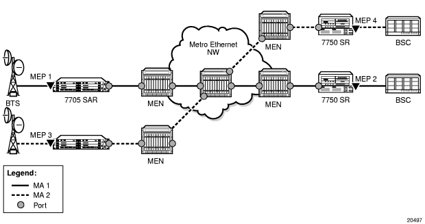
Figure 13 depicts a high-level view of MEPs in a CFM-enabled network. Two MAs are shown. The endpoints of MA 1 are MEPs 1 and 2, while MEPs 3 and 4 are the endpoints for MA 2.
For more information on MEP support, see Ethernet OAM.
Figure 13: MEPs and MAs
3.6.1.2. MEG Levels, MEGs, and MEPs (Y.1731)
On the 7705 SAR, the implementation of Y.1731 Fault Management (FM) is similar to that of dot1ag CFM, except that Y.1731 does not have a maintenance domain (MD). For Y.1731 and 802.1ag, the following terms are equivalent:
- MEG level is equivalent to MD level
- MEG is equivalent to MA
- a Y.1731 MEP is equivalent to a dot1ag MEP
To access Y.1731 functions, including Y.1731 Performance Monitoring (PM) functions, configure a MEP to have the domain format set to none and the association format set to icc-based or string (the string keyword enables the Y.1731 MEP to interoperate with a dot1ag MEP).
3.6.2. ETH-CFM Frame Format
ETH-CFM OAMPDU messages for 802.1ag and Y.1731 use a standard Ethernet frame (see Figure 14). The parts of the frame are described below.
Figure 14: ETH-CFM Frame Format

Destination and Source Addresses
The destination and source MAC addresses of the CFM message must match at the send and the receive routers. For example, a 7705 SAR-initiated ETH-CFM message would use the spoke SDP MAC address of the 7705 SAR as the source MAC address and the spoke SDP MAC address of the far-end router as the destination MAC address. At the far end, the source and destination MAC addresses would be the reverse of the near end.
An exception to the matching source-destination MAC address requirement occurs for linktrace and continuity messages, where the destination MAC address is set to a multicast group address. The designated multicast group address for linktrace and CCM is 01-80-C2-00-00-3x; where x represents the maintenance domain (MD) level (for 802.1ag) or the MEG level (for Y.1731). For example, a dot1ag CCM message destined for 01-80-C2-00-00-31 corresponds to MD level 1.
CCM packets using source-destination multicast MAC addresses are for user-initiated messages only (that is, loopbacks).
Ethertype (T)
If dot1q or qinq encapsulation is not configured, then the Ethertype value is 0x8902 and there are no VLAN tags. If dot1q or qinq encapsulation is configured, the VLAN tag (Ethertype value 0x8100) is present and is followed by the Ethertype value of 0x8902, which indicates ETH-CFM messages. The Ethertype is not hard-coded to 0x8100 and can be changed via the port configuration command.
VLAN/dot1p
This is the VLAN/dot1p identifier. If null encapsulation is configured (for Ethernet SAPs or spoke SDP bindings to a VC-type, ether or vlan), the frame is tagged with NULL.
ETH-CFM OAMPDU
The contents of the Ethernet OAMPDU depend on whether dot1ag or Y.1731 standards are being used. For details on the dot1ag or Y.1731 OAMPDU, see ETH-CFM OAMPDU.
FCS
This is the frame check sequence field.
3.6.2.1. ETH-CFM OAMPDU
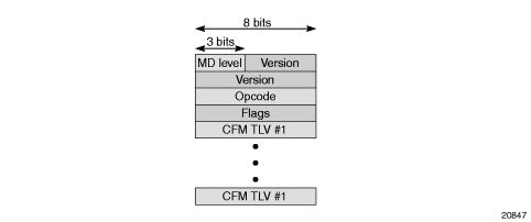
As shown in Figure 15, each ETH-CFM OAMPDU message contains the following fields:
- MD level or MEG level: user-configured value, 0 to 7
- version: current version is 0
- opcodes: as defined in IEEE 802.1ag and Y.1731 standards, for messages such as:
- Continuity Check Message (CCM)
- Loopback Message (LBM)
- Loopback Reply (LBR)
- Linktrace Message (LTM)
- Linktrace Reply (LTR)
- flags: as defined in IEEE 802.1ag and Y.1731 standards
- one or more TLVs, which include:
- End TLV
- Data TLV
- Reply Ingress TLV
- Reply Egress TLV
- LTM egress identifier TLV
- LTR egress identifier TLV
- Test TLV
Figure 15: ETH-CFM OAMPDU Message
3.6.2.2. CFM Frame Processing
Table 10 shows whether a CFM frame received by various MEP types is processed or not. Frames that are processed are extracted from the datapath for CFM processing; unprocessed frames are treated as user traffic and follow the user traffic rules.
Table 10: CFM Frame Processing
MEP Details | Received CFM Frame Treatment | ||||
MEP Type | Direction | VC-Type | Port | Untagged | Tagged 1 |
Spoke SDP | Down | Raw | Any | Processed | Not processed |
VLAN | Any | Not processed | Processed | ||
SAP | Down | Any | Dot1q or QinQ | Not processed 2 | Processed |
Any | Null | Processed | Not processed | ||
Up | Any | Dot1q or QinQ | Not processed | Processed | |
Any | Null | Processed | Not processed | ||
- Tagged frames are single-tagged frames (dot1q) or double-tagged frames (qinq).
- Untagged frames received on a dot1q-encapsulated port are processed by the Epipe configured to handle untagged frames. The SAP identifier on this Epipe uses VLAN ID 0, also referred to as SAP 0 (for example, 1/1/2:0). Untagged frames are also processed on the *.* QinQ SAP, and on a vlan-x.0 QinQ SAP only if the outer tag matches.
Notes:
3.6.2.2.1. Processing SAP 0 and SAP 0.* OAM Packets
The following points describe the processing of OAM packets on SAP 0 (dot1q) and SAP 0.* (qinq). SAP 0.0 is not supported on OAM packets.
- the 7705 SAR transmits untagged OAM frames on SAP 0 and SAP 0.*
- the 7705 SAR does not process OAM frames tagged with VLAN ID 0 or VLAN ID 0.* on a port configured with null encapsulation
- (for consistency with the 7710 SR) the 7705 SAR processes double-tagged or triple-tagged OAM frames under the following configuration scenario: there is a SAP Up MEP on a dot1q- or qinq-encapsulated port, using SAP 0 or 0.*, and having VC-type VLANIn this case, the top VLAN tag is removed and the bottom VLAN tag is assumed to be SAP 0 or 0.*. If the bottom VLAN tag is not SAP 0 or 0.*, the VLAN ID is changed to 0. If the frame is an OAM frame, double-tagged (or triple-tagged), the frame is extracted from the SAP Up MEP and the reply is with a single-tagged frame with its VLAN ID set to 0.
- on a SAP Down MEP (dot1q or qinq), untagged frames are processed on SAP 0 or 0.*
3.6.2.3. MEG-ID and ICC-Based Format
Similar to an 802.1ag MA-ID, a Y.1731 MEG-ID uniquely identifies a group of MEs that are associated at the same MEG level in one administrative domain. The features of MEG-IDs are:
- each MEG-ID must be globally unique
- if the MEG may be required for path setup across interoperator boundaries, then the MEG-ID must be available to other network operators
- the MEG-ID should not change while the MEG remains in existence
- the MEG-ID should be able to identify the network operator that is responsible for the MEG
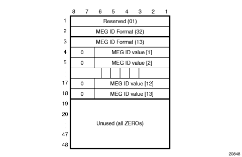
The 7705 SAR supports the ITU Carrier Code (ICC-based) MEG-ID format (TLV value 32). The generic and ICC-based MEG-ID formats are defined in the ITU-T Y.1731 standard. Figure 16 shows the ICC-based MEG-ID format.
The MEG-ID value has exactly 13 characters and consists of two subfields, the ITU Carrier Code (ICC) followed by a Unique MEG-ID Code (UMC). The ITU Carrier Code consists of between 1 and 6 left-justified characters (alphabetic or leading alphabetic with trailing numeric). The UMC code immediately follows the ICC and consists of between 7 and 12 characters, with trailing NULLs (if necessary to complete the 13 characters).
The UMC is the responsibility of the organization to which the ICC has been assigned, provided that uniqueness is guaranteed.
Figure 16: ICC-based MEG-ID Format
3.6.3. ETH-CFM Functions and Tests
The following list of ETH-CFM functions applies to both dot1ag and Y.1731 Ethernet OAM:
- ETH-CFM—ETH-CFM can be enabled or disabled on a SAP or spoke SDP
- MD levels—eight MD levels can be assigned
- MD name—the following MD name formats are supported:
- none (no MD name; used for specifying a Y.1731 functionality)
- DNS name
- MAC address and 2-octet integer
- character string
- MAs—MAs for each MD level can be configured, modified, or deleted
- each MA is defined by a unique combination of MD index, MD level, and MA index. This unique combination of values is called the MA identifier (MA-ID).
- the following MA name formats are supported:
- primary VLAN ID (VID)
- character string (when used with MD name format none, specifies Y.1731 interoperability with 802.1ag)
- 2-octet integer
- RFC 2685, Virtual Private Networks Identifier
- icc-based (used for specifying a Y.1731 functionality)
- when a VID is used as the MA name, CFM will not support VLAN translation because the unique MA-ID must match all the MEPs
- the default format for an MA name is a 2-octet integer; integer value 0 means that the MA is not attached to a VID.
- MEPs—Up and Down MEPs on a SAP, and Down MEPs on a spoke SDP
- MEPs can be configured, modified, or deleted for each MD level (both associations for the Up or Down MEP are with the same Bridge Port; as described in Section 19.2.1 of IEEE Standard 802.1ag-2007)
- each MEP is uniquely identified by its MEP identifier and MA-ID combination
- MEP creation—MEP creation on a SAP is allowed only for Ethernet ports (with null, dot1q, or qinq encapsulations)
3.6.3.1. ETH-CFM Ethernet OAM Tests
This section describes Ethernet OAM tests for ETH-CFM on the 7705 SAR, including:
- loopbacks
- linktrace
- throughput measurement
- continuity check
- remote defect indication
- alarm indication signal
- Ethernet (signal) test
3.6.3.1.1. Loopback (LB)
The loopback function is supported by 802.1ag and Y.1731 on the 7705 SAR. A Loopback Message (LBM) is generated by a MEP to its peer MEP. Both dot1ag and dot3ah loopbacks are supported. The loopback function is similar to IP or MPLS ping in that it verifies Ethernet connectivity between the nodes on a per-request basis. That is, it is non-periodic and is only initiated by a user request.
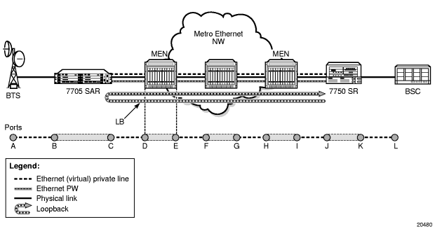
In Figure 17, the line labeled LB represents the dot1ag loopback message between the 7750 SR (source) and 7705 SAR (target). The 7750 SR-generated LBM is switched to the 7705 SAR, where the LBM message is processed. Once the 7705 SAR generates the Loopback Reply message (LBR), the LBR is switched over the PW to the 7750 SR.
The following loopback-related functions are supported:
- loopback message functionality on a MEP can be enabled or disabled
- MEP—supports generating loopback messages and responding to loopback messages with loopback reply messages
- displays the loopback test results on the originating MEP
Figure 17: Dot1ag Loopback Test
3.6.3.1.2. Linktrace (LT)
The linktrace function is supported by 802.1ag and Y.1731 on the 7705 SAR. A Linktrace Message (LTM) is originated by a MEP and targeted to a peer MEP in the same MA and within the same MD level. Its function is similar to IP traceroute. The peer MEP responds with a Linktrace Reply (LTR) message after successful inspection of the LTM.
The following linktrace related functions are supported:
- enables/disables LT functions on an MEP
- MEP—supports generating LTMs and responding with LTR messages
- displays linktrace test results on the originating MEP
3.6.3.1.3. Throughput Measurement
Throughput measurement is performed by sending frames to the far end at an increasing rate (up to wire speed) and measuring the percentage of frames received back. In general, the rate is dependent on frame size; the larger the frame size, the lower the rate.
The Y.1731 specification recommends the use of unicast ETH-LB and ETH-Test frames to measure throughput.
On the 7705 SAR, LBM processing and LBR generation are enhanced and occur on the datapath, allowing the 7705 SAR to respond to loopback messages at wire speed and making in-service throughput tests possible. Thus, if the 7705 SAR receives LBMs at up to wire speed, it can generate up to an equal number of LBRs.
In order to process LBMs at wire speed, there must be either no TLVs or a single TLV (which is a Data TLV) in the LBM frame. The End TLV field (0) must be present and the frame can be padded with data after the End TLV field in order to increase the size of the frame. Note, however, that the MAC address cannot be a multicast MAC address; it must be the MEP MAC destination address (DA).
Datapath processing of LBMs is supported for the following MEPs:
- dot1ag
- SAP Up MEP
- SAP Down MEP
- spoke SDP Down MEP
- Y.1731
- SAP Up MEP
- SAP Down MEP
For spoke SDP Down MEPs, fastpath (datapath) LBM processing requires that both interfaces—the LBM receiver and the LBR transmitter—reside on the same adapter card. For example, if the 7705 SAR must perform a reroute operation and needs to move the next-hop interface to another adapter card (that is, LBMs are received on one card and LBRs are transmitted on another), then the fastpath processing of LBMs is terminated and LBM processing continues via the CSM.
3.6.3.1.4. Continuity Check (CC)
The continuity check function is supported by 802.1ag and Y.1731 on the 7705 SAR. A Continuity Check Message (CCM) is a multicast frame that is generated by a MEP and sent to its remote MEPs in the same MA. The CCM does not require a reply message. To identify faults, the receiving MEP maintains a MEP database with the MAC addresses of the remote MEPs with which it expects to maintain connectivity checking. The MEP database can be provisioned manually. If there is no CCM from a monitored remote MEP in a preconfigured period, the local MEP raises an alarm.
The following CC capabilities are supported:
- enable and disable CC for a MEP
- automatically put local MEPs into the database when they are created
- manually configure and delete the MEP entries in the CC MEP monitoring database. The only local provisioning required to identify a remote MEP is the remote MEP identifier (using the remote-mepid mep-id command).
- CCM transmit interval: 10ms, 100ms, 1s, 10s, 1m, 10m (default: 10s)
- transmit interval: 10ms, 100ms, 1s, 10s, 1m, 10m (default: 10s)
- CCM declares a fault when it:
- stops hearing from one of the remote MEPs for a period of 3.5 times the CC interval
- hears from a MEP with a lower MD level
- hears from a MEP that is not in the same MA
- hears from a MEP that is in the same MA but is not in the configured MEP list
- hears from a MEP that is in the same MA with the same MEP ID as the receiving MEP
- recognizes that the CC interval of the remote MEP does not match the local configured CC interval
- recognizes that the remote MEP declares a faultAn alarm is raised and a trap is sent if the defect is greater than or equal to the configured low-priority-defect value.
- CC must be enabled in order for RDI information to be carried in the CCM OAMPDU
3.6.3.1.5. ETH-RDI
The Ethernet Remote Defect Indication function (ETH-RDI) is used by a MEP to communicate to its peer MEPs that a defect condition has been encountered. Defect conditions such as signal fail and AIS may result in the transmission of frames with ETH-RDI information. ETH-RDI is used only when ETH-CC transmission is enabled.
ETH-RDI has the following two applications:
- single-ended fault management—the receiving MEP detects an RDI defect condition, which gets correlated with other defect conditions in this MEP and may become a fault cause. The absence of received ETH-RDI information in a single MEP indicates the absence of defects in the entire MEG.
- contribution to far-end performance monitoring—the transmitting MEP reflects that there was a defect at the far end, which is used as an input to the performance monitoring process
A MEP that is in a defect condition transmits frames with ETH-RDI information. A MEP, upon receiving frames with ETH-RDI information, determines that its peer MEP has encountered a defect condition.
The specific configuration information required by a MEP to support the ETH-RDI function is as follows:
- MEG level—the MEG level at which the MEP exists
- ETH-RDI transmission period—application-dependent and is the same value as the ETH-CC transmission period
- priority—the priority of frames containing ETH-RDI information and is the same value as the ETH-CC priority
The PDU used to carry ETH-RDI information is the CCM.
3.6.3.1.6. ETH-AIS
The Ethernet Alarm Indication Signal function (ETH-AIS) is a Y.1731 CFM enhancement used to suppress alarms at the client (sub) layer following detection of defect conditions at the server (sub) layer.
Transmission of frames with ETH-AIS information can be enabled or disabled on a Y.1731 MEP.
Frames with ETH-AIS information can be issued at the client MEG level by a MEP, including a server MEP, upon detecting the following conditions:
- signal failure conditions in the case where ETH-CC is enabled
- AIS condition in the case where ETH-CC is disabled
For a point-to-point Ethernet connection at the client (sub) layer, a client layer MEP can determine that the server (sub) layer entity providing connectivity to its peer MEP has encountered a defect condition upon receiving a frame with ETH-AIS information. Alarm suppression is simplified by the fact that a MEP is expected to suppress only those defect conditions associated with its peer MEP.
Only a MEP, including a server MEP, is configured to issue frames with ETH-AIS information. Upon detecting a defect condition, the MEP can immediately start transmitting periodic frames with ETH-AIS information at a configured client MEG level. A MEP continues to transmit periodic frames with ETH-AIS information until the defect condition is removed. Upon receiving a frame with ETH-AIS information from its server (sub) layer, a client (sub) layer MEP detects the AIS condition and suppresses alarms associated with all its peer MEPs. Once the AIS condition is cleared, a MEP resumes alarm generation upon detecting defect conditions.
The following specific configuration information is required by a MEP to support ETH-AIS:
- client MEG level—the MEG level at which the most immediate client layer MEPs exist
- ETH-AIS transmission period—the transmission period of frames with ETH-AIS information
- priority—the priority of frames with ETH-AIS information
3.6.3.1.7. ETH-Test
The Ethernet Test (signal) function (ETH-Test) is a Y.1731 CFM enhancement used to perform one-way, on-demand, in-service diagnostics tests, which include verifying frame loss, bit errors, and so on.
| Note: The out-of-service diagnostics test is not supported on the 7705 SAR. |
When configured to perform such tests, a MEP inserts frames with ETH-Test information such as frame size and transmission patterns.
When an in-service ETH-Test function is performed, data traffic is not disrupted and the frames with ETH-Test information are transmitted.
To support ETH-Test, a Y.1731 MEP requires the following configuration information:
- MEG level—the MEG level at which the MEP exists
- unicast MAC address—the unicast MAC address of the peer MEP for which ETH-Test is intended
- data—an optional element with which to configure data length and contents for the MEP. The contents can be a test pattern and an optional checksum.Examples of test patterns include all 0s or all 1s. At the transmitting MEP, this configuration information is required for a test signal generator that is associated with the MEP. At the receiving MEP, this configuration is required for a test signal detector that is associated with the MEP.
- priority—the priority of frames with ETH-Test information
A MEP inserts frames with ETH-Test information towards a targeted peer MEP. The receiving MEP detects the frames with ETH-Test information and performs the requested measurements.
3.6.4. MEP Support (802.1ag and Y.1731)
The 7705 SAR supports Up and Down maintenance association endpoints (MEPs) on Ethernet SAPs for both 802.1ag and Y.1731. It also supports Down MEPs on Ethernet spoke SDPs for 802.1ag only.
3.6.4.1. 802.1ag MEP Support on Ethernet SAPs
The 7705 SAR supports Up and Down MEPs on Ethernet SAPs. Figure 18 shows that the 7705 SAR can terminate and respond to CFM messages received from connected devices, such as base stations, when port B is a Down MEP on a SAP. A CFM message coming from port A would be terminated on port B of the 7705 SAR. As well, port B on the 7705 SAR can generate and send a CFM message towards port A.
Figure 18: MEP on Ethernet Access
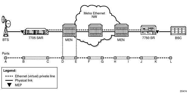
Figure 19 shows how a Down MEP on an Ethernet SAP might be used. In this example, an Ethernet network connects to an access Ethernet port on the 7705 SAR and there are multiple SAPs on that port (that is, multiple endpoints). Since CFM offers OAM capabilities on a per-service basis, which in this case means per SAP (or endpoint), each service can run CFM. If BSC end devices were directly connected to the 7705 SAR (and a VLAN was not used to separate services from each other), EFM would offer capabilities similar to CFM for Ethernet OAM.
In the example shown in Figure 19, separate dot1ag instances initiated on the 9500 MPR nodes can be used to ensure Ethernet layer connectivity on a per-base-station basis. All the traffic from these base stations is aggregated and switched to a single port on the 7705 SAR. Each base station is recognized through a different VLAN, where the VLANs are bound to different services. CFM with traffic in the Down MEP OAMPDU direction at the Ethernet SAP offers the flexibility to run OAM tests on a per-base-station basis.
Figure 19: Down MEP at Ethernet SAP
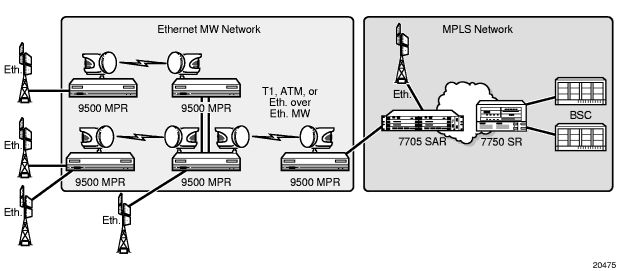
3.6.4.2. 802.1ag MEP Support on Ethernet Spoke SDPs
The 7705 SAR supports down maintenance association endpoints (MEPs) on Ethernet spoke SDP endpoints. Figure 20 illustrates a Down MEP on an Ethernet spoke SDP.
CFM messages can be generated and switched across an Ethernet PW. CFM messages that are received and have an MD that matches the value configured on the 7705 SAR are extracted and processed. Any received CFM messages with an MD level that does not match the configured value are not terminated and are switched transparently to the Ethernet SAP.
Down MEPs on Ethernet spoke SDPs on the 7705 SAR support the following:
- termination of the CFM messages destined for the MEP-ID of the 7705 SAR
- termination of CFM messages at the user-configured domain only
- discarding of OAMPDUs at a lower MD level than the configured one (an alarm message is raised)
- transparent pass-through of upper layer CFM messages
- MD of the CFM messages that are higher than the one configured on the 7705 SAR
MIP functionality (that is, forwarding of CFM messages with the same MD level) is not supported. Only Down MEP functionality is supported on Ethernet spoke SDPs (that is, termination of CFM messages that are ingress from the Ethernet PW, or generation of CFM packets that are destined for the 7750 SR spoke SDP MEP-ID).
Figure 20: Dot1ag Down MEPs on Spoke SDPs
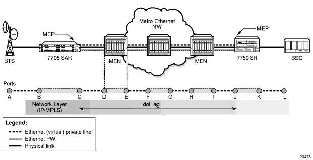
In Figure 20, assuming that the MEP is enabled both on the SR and the 7705 SAR spoke SDP endpoints, the 7705 SAR can generate CFM messages and can terminate any received CFM messages that are destined for the 7705 SAR MEP-ID and have a matching configured domain. Any 7705 SAR-generated CFM packets would traverse the Ethernet PW and would be processed first by the SR node. The Ethernet PW running between the 7705 SAR and the SR generates a pipe-like connectivity; thus, no intermediate Ethernet node can process the CFM messages. All the CFM messages are transported over Ethernet PWs, and PW termination only takes place on SR and 7705 SAR endpoints.
3.6.4.3. Y.1731 MEP Support on Ethernet SAPs
As shown in Figure 21, the 7705 SAR supports Y.1731 Up and Down MEPs on Ethernet SAPs that are bound to an Ethernet PW service.
Figure 21 also shows an 802.1ag Down MEP on an Ethernet spoke SDP in order to illustrate that when performing CFM tests on the 7705 SAR, a Y.1731 Up MEP on an Ethernet SAP should be used instead of an 802.1ag Down MEP on an Ethernet spoke SDP. Using a Y.1731 SAP Up MEP means that CFM packets verify the switching fabric and SAP status before the packet is processed, because the SAP is on the access side of the 7705 SAR whereas a spoke SDP is on the network side. If a spoke SDP Down MEP is used, packets are terminated and extracted on the network side without being switched through the switching fabric.
Figure 21: Y.1731 MEP Support on the 7705 SAR
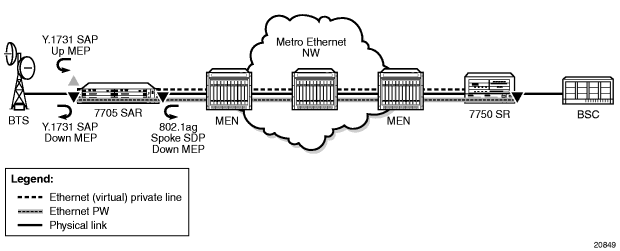
3.6.5. Priority Mapping (802.1ag and Y.1731)
Operators often run OAM tests over a single, specific forwarding class (FC). For example, an operator might be mapping OAM traffic to FC2 (AF – Assured Forwarding) and, in order to examine the delay, jitter, or loss qualities of the OAM traffic, would need to run OAM tests using FC2. To provide operators with the ability to control which FC the OAM packets will follow, the priority priority command is included in several OAM test commands.
When the 7705 SAR generates an Ethernet OAM frame, it uses the priority as per the user’s configuration of the priority keyword and then sends the frame through the datapath. Thus, the OAM frame follows the entire datapath and receives the same treatment as any other user frame before it is switched over the port.
For example, a CCM frame generated by a SAP Up MEP with a priority value of 7 will receive the following treatment.
- First, the CCM frame is classified as per the access ingress and QoS policy settings. For example, the CCM frame can be mapped to the BE forwarding class if the assigned QoS policy has its priority 7 mapped to BE.
- Then, the OAM packet is mapped to the associated queue (the queue hosting the BE forwarding class) and follows ingress scheduling like any other datapath frame.
- Next, the CCM frame is switched through the fabric and reclassified to the network egress queues, as per the assigned QoS policy classifiers.
- Finally, the CCM frame is scheduled again, as per the queue type and profile state of the queue.
This implementation replicates the user experience since the OAM packet follows the same path as the data packets.
3.6.5.1. Priority Mapping for SAP Up MEPs
For Up MEPs on a SAP, priority mapping operates as described in the following list, which indicates how the messages or replies generated on ingress have their FC and VLAN tag priority set.
The resulting frames (CCM, LMM, DMM, 1DM, LBM, LMR, DMR, or LBR) are inserted in the access ingress datapath and are processed in the same way as any other frame. That is, they are classified based on the sap-ingress policy.
- Continuity Check messages (CCMs) generated on ingress are based on the setting of the ccm-ltm-prio command for the MEP (that is, the VLAN tag priority is set according to the ccm-ltm-prio command for the MEP).
- Loss Measurement messages (LMMs), two-way Delay Measurement messages (DMMs), one-way Delay Measurement messages (1DMs), and Loopback messages (LBMs) generated on ingress are based on the priority specified during the LMM, DMM, 1DM, or LBM test (that is, the VLAN tag priority is set according to the priority specified during the test).
- Loss Measurement replies (LMRs), two-way Delay Measurement replies (DMRs), and Loopback replies (LBRs) generated on ingress keep the VLAN tag priority of their corresponding LMM or DMM frame.
Table 11 summarizes the 7705 SAR FC and VLAN priority mappings for SAP Up and Down MEPs based on the frame type.
Table 11: FC and VLAN Priority Mappings for Up and Down MEPs as per Frame Type
MEP Type | Frame Type (Tx) | FC | VLAN priority |
SAP Up MEP | CCM | derived from vlan-prio after classification | ccm-ltm-prio |
LMM, DMM, 1DM, LBM | derived from vlan-prio after classification | user-specified | |
LMR, DMR, LBR | derived from vlan-prio after classification | preserve incoming query priority | |
SAP Down MEP | CCM | ccm-ltm-prio | ccm-ltm-prio |
LMM, DMM, 1DM, LBM | user-specified | user-specified | |
LMR, DMR, LBR | ccm-ltm-prio | incoming tag priority |
3.6.5.2. Priority Mapping for SAP Down MEPs
For SAP Down MEPs, priority mapping operates as described in the following list, which indicates how the messages or replies generated on egress have their FC and VLAN tag priority set.
- CCMs generated on egress are based on ccm-ltm-prio of the MEP (that is, FC and VLAN tag priority are set according to the ccm-ltm-prio of the MEP).
- LMM, DMM and 1DM generated on egress are based on the priority specified during the test (that is, FC and VLAN tag priority are set according to the priority specified during the test).
- LMR, DMR, and LBR generated on egress use the ccm-ltm-prio of the MEP as FC. The VLAN tag priority is not replaced (that is, the VLAN tag priority of LMM and DMM are kept).
3.7. QinQ Support
This section contains the following topics:
3.7.1. Overview of QinQ
On the 7705 SAR, QinQ (also referred to as VLAN stacking) is based on the IEEE 802.1ad specification. QinQ allows a service provider to use a single VLAN for customers needing multiple VLANs by adding a second VLAN tag to an Ethernet frame, as shown in Figure 22. QinQ encapsulation can be thought of as a dot1q within a dot1q encapsulation.
QinQ operates from end-to-end by receiving customer frames on an ingress SAP, transporting the frames over a service tunnel, and receiving them at the far-end router, where they are unpacked and sent through the egress SAP to the customer.
Figure 22: QinQ Frame
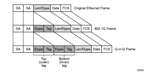
On the 7705 SAR, QinQ ports and QinQ SAPs offer the same feature set as dot1q ports and dot1q SAPs for the following features:
- OAM
- redundancy
- synchronization
- QoS
- card and node limits
QinQ is supported on the following service SAPs (including SAP-to-SAP configurations):
- VLL services (Epipe and Ipipe)
- VPLS
- VPRN
- IES
QinQ is supported on the following adapter cards, modules, and nodes:
- 8-port Ethernet Adapter card, version 2
- 6-port Ethernet 10Gbps Adapter card
- 8-port Gigabit Ethernet Adapter card (all versions)
- 10-port 1GigE/1-port 10GigE X-Adapter Card, version 2 (10-port 1GigE mode)
- Packet Microwave Adapter card
- 4-port SAR-H Fast Ethernet module
- 6-port SAR-M Ethernet module
- 7705 SAR-M
- 7705 SAR-A
- 7705 SAR-Ax
- 7705 SAR-W
- 7705 SAR-Wx (Ethernet ports and DSL ports)
- 7705 SAR-H
- 7705 SAR-Hc
- 7705 SAR-X
| Note: QinQ is not supported by DSL and GPON modules on the 7705 SAR-M. |
Figure 23 shows an example of QinQ tagging, where three customer sites each use the same service provider PE router to transport multiple VLANs across an MPLS network. Customer 1 sends an Ethernet frame without a VLAN tag (null encapsulation) and the provider uses MPLS label 25. Customer 2 sends dot1q frames (VLAN ID 20) and the provider uses MPLS label 35. Lastly, customer 3 sends a qinq frame (VLAN ID 10:300) and the provider uses MPLS label 45.
For details on VLAN translation in an Ethernet frame from ingress SAP to egress SAP, see Raw and Tagged Modes.
Figure 23: QinQ Tagging Example
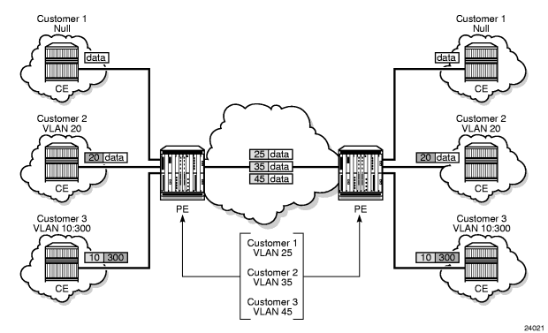
3.7.2. QinQ Support with Forced C-Tag Forwarding (VPLS only)
For VPLS, force-c-vlan-forwarding can be user-configured as enabled or disabled. When force-c-vlan-forwarding is enabled at the ingress and egress SAPs, the VLAN tag transmitted at the far-end egress SAP is the same as the VLAN tag received at the near-end ingress SAP.
The following examples illustrate the QinQ implementation. Example 1 is a general example. Examples 2 and 3 are examples where the 7705 SAR parses a single frame that has three VLAN tags. For examples 2 and 3, the innermost VLAN Ethertype is always set to 0x8100.
3.7.2.1. Example 1: General QinQ Implementation
When a service has multiple SAPs configured that can match an incoming frame, the SAP with the most explicit match transmits the frame. For this example, assume that the following SAPs are configured on a port and that the port is in QinQ mode:
- SAP_1 identifier is port-id:vlan-x.vlan-y
- SAP_2 identifier is port-id:vlan-x.*
- SAP_3 identifier is port-id:*.*
For an incoming frame with VLAN tags vlan-x.vlan-y, SAP_1 processes the frame because it is the most explicit match. Although SAP_2 and SAP_3 also match the frame, the most explicit SAP prevails.
3.7.2.2. Example 2: QinQ using VPLS with Ethernet SAPs
In this example, assume that the 7705 SAR parses a single frame that has three VLAN tags (innermost VLAN Ethertype is always set to 0x8100). This might occur in the scenario shown in Figure 24, where VPLS QinQ SAPs with force-c-vlan-forwarding enabled connect Customer 1 and Customer 2 and preserve the ingress VLAN tag.
Figure 24: QinQ Using VPLS Ethernet SAPs
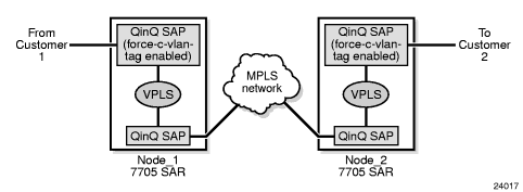
In Figure 24, the following events occur.
- At Node_1, an ingress QinQ SAP with force-c-vlan-forwarding enabled receives a frame and ensures that the bottom (inner) tag is preserved. The frame is then sent to an egress qinq-encapsulated SAP, where the top (outer) tag is swapped and an additional (third) tag is pushed on top.
- At Node_2, the frame with three tags is received on a qinq-encapsulated SAP. The frame is then sent to an egress QinQ SAP with force-c-vlan-forwarding enabled, where the egress qinq-encapsulation SAP:
- removes the first (top) tag
- replaces the second (middle) tag
- replaces only the Ethertype of the third (bottom/innermost) tag (that is, the VLAN ID is not replaced)
3.7.2.3. Example 3: QinQ Using VPLS with ATM SAPs
A second example of triple-tag behavior is shown in Figure 25, where customers are connected using ATM SAPs with subscriber-vlan enabled.
Figure 25: QinQ Using VPLS ATM SAPs
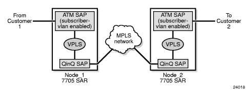
In this example, the ATM SAP with subscriber-vlan enabled pushes a tag on the frame at ingress. The frame is then sent toward a qinq-encapsulated SAP on egress, which pushes two more tags onto the frame. At the far end, the frame (with three tags) is received on a qinq-encapsulated SAP and sent toward the egress ATM SAP with subscriber-vlan enabled. In this case, the egress ATM-encapsulated SAP must be able to remove the three tags.
3.7.3. QinQ Support on Ethernet Ports
This section contains the following topics:
QinQ requires that the encap-type for the associated port be set for qinq, and that the sap-id include two Q-tags (VLAN IDs). An ingress QinQ SAP can be configured so that dot1p bits for packet QoS classification can come from the top or the bottom Q-tag. At egress, if dot1p re-marking is configured, both Q-tags are re-marked. However, you can use qinq-mark-top-only to re-mark only the top Q-tag.
3.7.3.1. Special QinQ SAP Identifiers
Table 12 describes the special SAP identifiers used on the 7705 SAR. In Table 12, a qtag value represents a VLAN ID. The * (asterisk) represents a reserved VLAN that is used to carry traffic from any unused VLAN on the port. An unused VLAN is a VLAN that is not explicitly defined on the port.
Table 12: Special QinQ SAP Identifiers
QinQ SAP Type | SAP Identifier | Example | Notes |
Explicit (specified) | port-id:qtag1.qtag2 1 | 1/1/1:20.2000 | qtag1 and qtag2 range: 0 to 4094, and * |
Null | port-id port-id:0 port-id:0.* | 1/1/1 1/1/1:0 1/1/1:0.* | No suffix means no VLANs 0 suffix means SAP 0 0.* suffix means SAP 0 and any unused VLAN on the port |
Default | port-id:* port-id:*.* port-id:qtag1.* | 1/1/1:* 1/1/1:*.* 1/1/1:40.* | *.* means any unused VLAN on the port 2 |
- qtag1 is the top (outer) tag. qtag2 is the bottom (inner) tag.
- The behavior of the *.* SAP on the 7705 SAR is different from the *.* SAP behavior on the 7750 SR. On the 7750 SR, *.* represents a capture SAP.
Notes:
| Note: The following default SAPs are not supported on the 7705 SAR:
|
The following list describes how the SAP types in Table 12 process frames. Packet breakdowns are described in Raw and Tagged Modes.
- default SAP (port-id:qtag1.*)
- receives all frames with an explicit outer tag value of qtag1, regardless of the inner tag
- the outer tag is stripped and the inner tag is passed transparently
- example: SAP 1/1/1:10.* only matches a top Q tag of VLAN 10. The SAP may have any bottom tag or no bottom tag at all.
- null SAP (port-id:0.*)
- receives all untagged frames and/or any frames with a VLAN tag of 0
- example: SAP 1/1/1:0.* allows any untagged frames and/or frames with an outer tag of “0” onlyIf the outer tag is 10, then the frame is dropped. If the outer tag is 0 and the inner tag is any valid VLAN ID, then the frame is not dropped.
- null inner SAP (port-id:qtag1.0)
- receives all frames with explicit outer tag value qtag1, and may have an inner tag of 0 or no inner tag at all
- example: SAP 1/1/1:10.0 or SAP 1/1/1:10 will only match “10” as the outer tag, and may have a bottom tag of 0 or no bottom tag at all. The SAP 1/1/1:1/10 will be dropped because its outer tag is not “10”.
- invalid SAPs (not supported) (port-id:*.qtag2 and port-id:*.0)
3.7.3.2. QinQ Dot1p Match Behavior
Since a qinq-encapsulated packet has top and bottom Q-tags, you can specify which qtag position provides the dot1p bits (P-bits) when QoS evaluates the P-bits in an ingress packet for a classification match. This is done with the sap>ingress>match-qinq-dot1p command. The default setting is to use the P-bits from the inner (bottom) Q-tag, or if the ingress packet has no Q-tags or has null encapsulation, then no match filtering is done.
3.7.3.3. QinQ Top-Only Mark Option
By default, if dot1p re-marking is configured at SAP egress on a QinQ SAP, the dot1p bits for both the top and bottom tags are re-marked. However, re-marking can be configured such that only the top Q-tag P-bits get remarked by enabling the sap>egress>qinq-mark-top-only command. The DEI bit is ignored.
3.7.3.4. Maximum Number of VLAN Tags
The maximum number of VLAN tags allowed in a packet depends on whether the service requires Layer 3 packet parsing (for example, to access to the IP header), as follows.
- For services that do not require access to the Layer 3 IP header, such as Ethernet PWs and VPLS, there is no limit on the number of VLAN tags in the packet. Any packet with any number of VLAN tags is accepted.
- For services that require access to the Layer 3 IP header, such as IP PWs, IES, and VPRN, there is a limit of three or fewer VLAN tags. When a packet is received that has four VLAN tags, the data following the third VLAN tag is considered as an IP packet. As a result, packets with four VLAN tags will be dropped by these services due to the inability to decode the IP header.
3.7.4. QinQ Configuration Overview
The basic steps to configure QinQ are as follows.
- Configure the port encap-type for qinq and (optionally) set the Ethertype (qinq-etype).
- Create one or more SAPs for the service.
- Configure the SAP ingress dot1p re-marking behavior (match the top or bottom tag).
- Enable the SAP egress qinq-mark-top-only command.
- Configure the spoke SDP vc-type (ether or vlan).
3.8. Service Creation Overview
Figure 26 shows a flowchart that provides an overview of the process to create a service. Service creation can be separated into two main functional areas—core services tasks and subscriber services tasks. Core services tasks are performed prior to subscriber services tasks.
Before starting the process shown in Figure 26, ensure that the 7705 SAR system has been configured with an IP address and (for the 7705 SAR-8 or 7705 SAR-18) has the appropriate adapter cards installed and activated.
Core services tasks include the following items:
- create customer accounts
- create template QoS and accounting policies
- create LSPs
- create SDPs
Subscriber services tasks include the following items:
- create VLL (Apipe, Cpipe, Epipe, Fpipe, Hpipe, or Ipipe), IES, VPLS, or VPRN services
- configure SAPs
- bind SDPs
- create exclusive QoS policies
- (optionally) assign IP filter policies to Epipe SAPs, Ipipe SAPs, VPLS SAPs, VPRN interface SAPs, IES interface SAPs, and IES Management interface SAPs. IP filter policies can also be applied to VPLS SDPs (ingress mesh and spoke), and VPRN and IES interface ingress spoke SDPs.
- (optionally) assign MAC ingress filter policies to VPLS SAPs and VPLS SDPs (mesh and spoke)
Figure 26: Service Creation and Implementation Flowchart
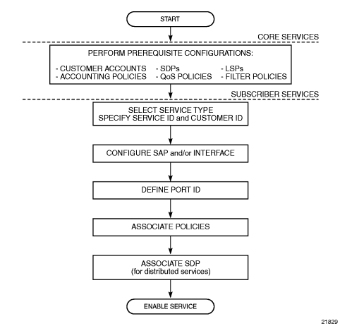
3.9. Port and SAP CLI Identifiers
When typing text in the command line interface (CLI), port-id is often displayed to indicate that a port identifier may need to be typed in the command line. Similarly, to identify a SAP, the port-id is used, but additional information may need to be appended to indicate a logical sub-element of the port.
On the CLI, a port-id is defined using the format slot/mda/port, where slot identifies the IOM card slot (always 1), mda identifies the physical slot in the chassis for the adapter card, and port identifies the physical port on the adapter card.
The value that can be appended to a SAP has the format [:ID], [.ID], [:ID/ID], or [:ID.ID]. The colon or dot and following ID identify a sub-element of the port (if applicable), such as a TDM channel group for a Cpipe, a VPI/VCI value for an Apipe, or a dot1q or qinq VLAN ID for an Epipe.
For example, a SAP associated with a TDM channel group on port 12 of an 16-port T1/E1 ASAP Adapter card in MDA slot 3 is identified as <1/3/12.3>, where “.3” is the appended value and identifies that for this SAP the channel group begins in timeslot 3.
3.9.1. Reference Sources
For information on standards and supported MIBs, refer to Standards and Protocol Support.