In Figure 1, service router A is connected to the ATM switch or 7670 RSP through an OCx ATM 1 link. This link is configured as the working circuit. Service router B is connected to the same ATM switch or 7670 RSP through an OCx ATM 2 link. This link is configured as the protection circuit.
Figure 1. Multi-chassis APS application
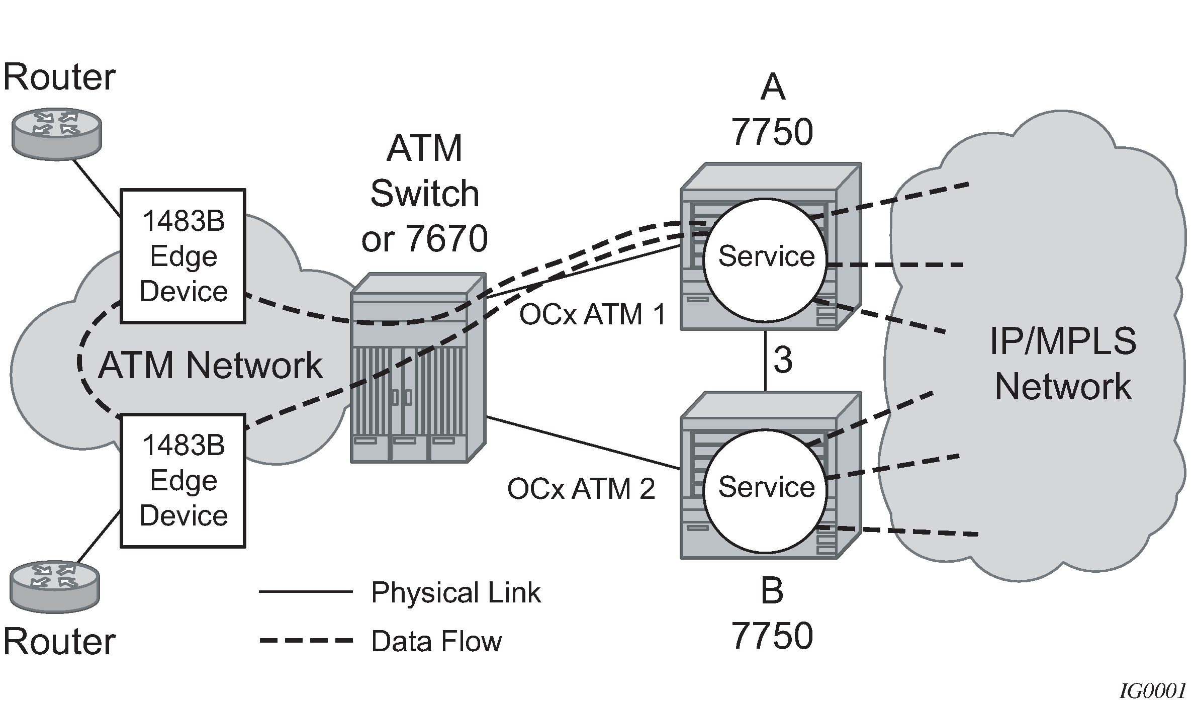
Communication between service routers A and B is established through link 3. This link is for signaling. To guarantee optimum fail-over time between service routers A and B, link 3 must be a direct physical link between routers A and B.