The origination function continues to operate as in previous releases. The only change is the ability to insert the user configured address in the source address field of the GRE/IPv4 header as described in Introduction and feature configuration.
The service manager does not explicitly request from the LDP module that an SDP auto-generated T-LDP session for the MPLS-over-GRE SDP uses the source address configured with the local-end CLI command. LDP ensures that either a user-configured T-LDP session, or a peer template based auto-created T-LDP session, exists and is connected to the far-end address of the SDP. LDP uses one of these sessions, or auto-creates one using the default local transport address of system.
Consequently, if the source transport address used by the T-LDP control plane session does not match the destination transport address set by the remote PE in the targeted LDP Hello messages, the T-LDP session does not come up.
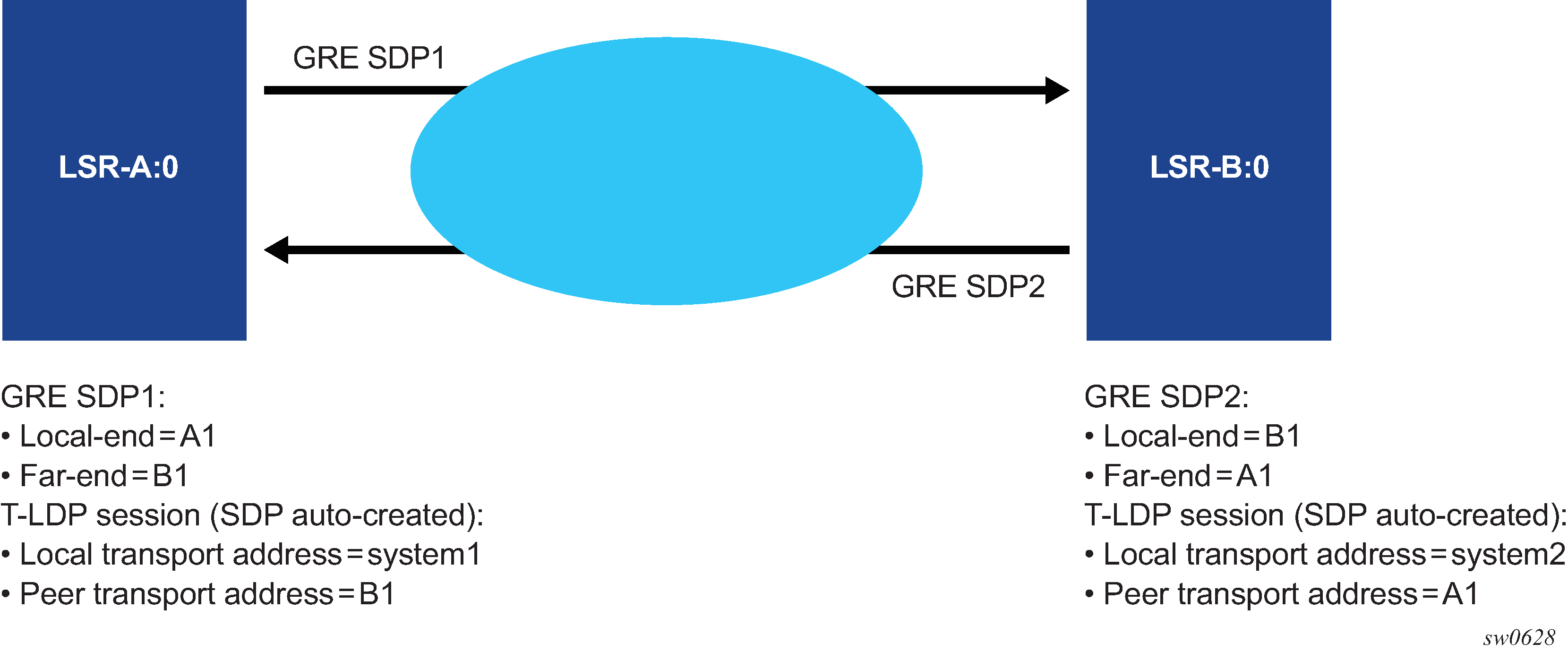
For example, the setup in Figure 1 results in both GRE SDP1 and SDP2 to remain down because the targeted Hello adjacency and LDP session does not come up between the two LDP LSRs.

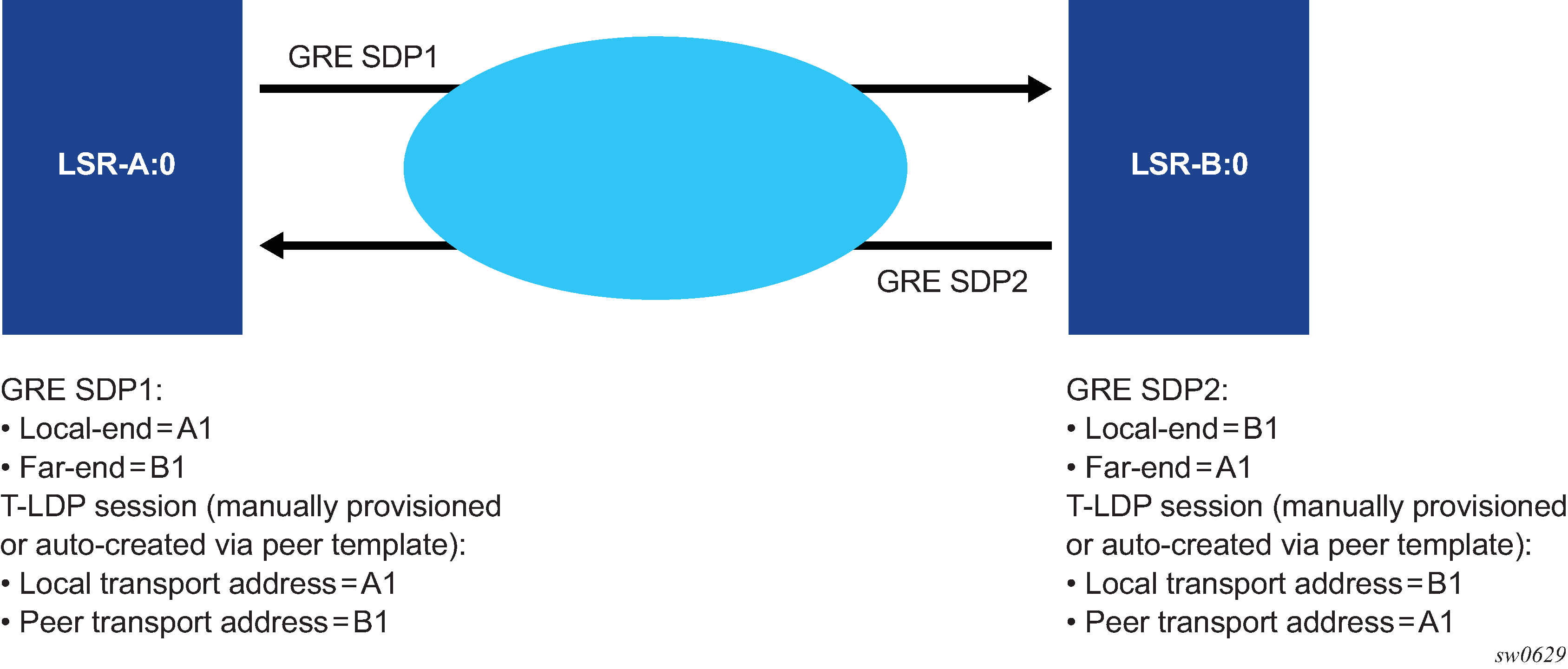
The user must match the local transport address of the T-LDP session to the local-end address of the GRE SDP in both the local and remote PE routers. This can be achieved by manually configuring a T-LDP session to the peer, or by auto-creating a T-LDP session with the targeted peer template feature, and setting the local-lsr-id command to the address configured in the local-end command of the GRE SDP. In addition, the far-end address must be in a GRE termination subnet at the remote PE and be the primary address of an interface in order for T-LDP to use it as its local LSR ID at the remote PE. Figure 2 shows an example of a correct configuration.

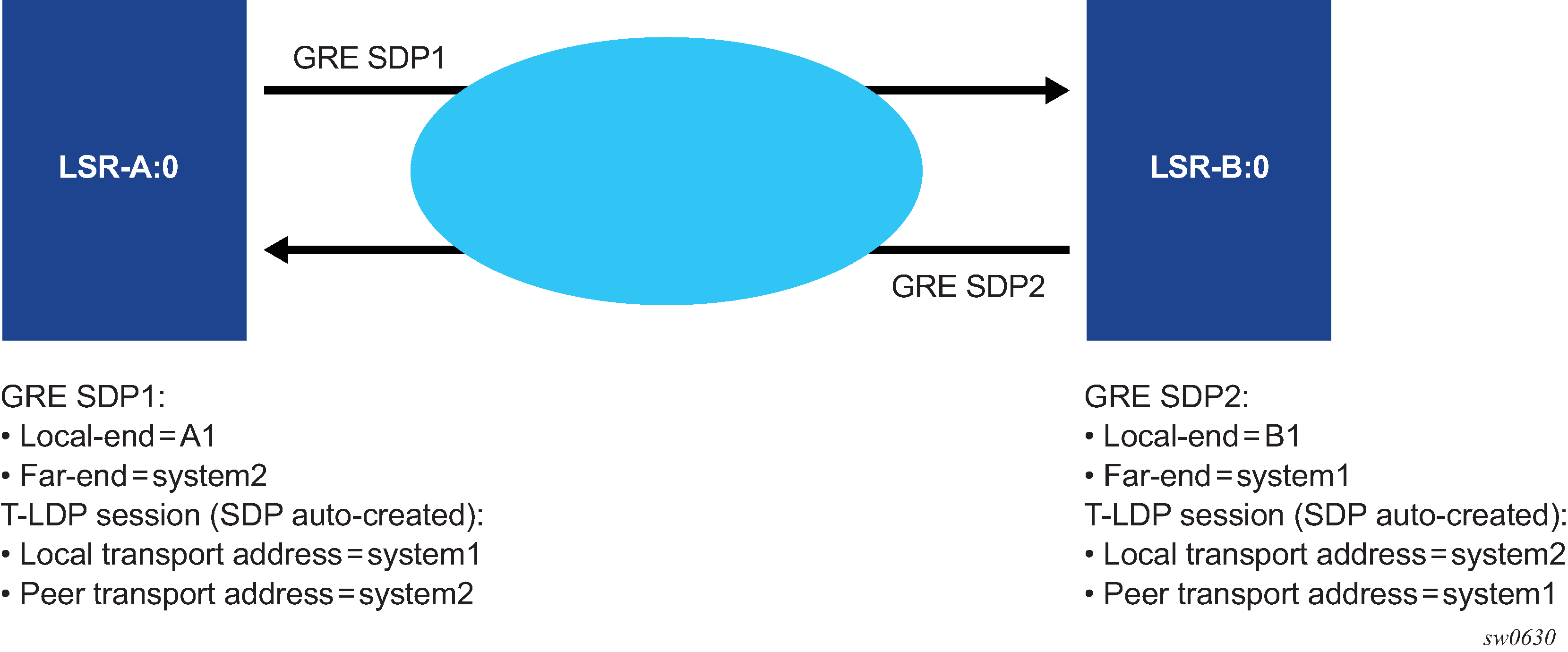
The source address used by the GRE tunnel in the data plane can be different than the local transport address used by T-LDP in the control plane and the GRE SDPs still come up. For example, the setup in Figure 3 uses at each end the system address for the T-LDP session but uses a loopback interface address as the source address of the GRE SDP.

The LDP uses a priority mechanism to select which parameters to use to instantiate a T-LDP session to the same far-end transport address. A manually provisioned T-LDP session overrides one that is signaled using the targeted peer template which overrides one that is auto-created by an SDP. This is done automatically by LDP by issuing, an ad-hoc update to the Hello message to the far-end with the new parameters. As long as the corresponding change is performed at the far-end router to match the local-end parameter change (for example, changing the local transport address requires a change of the far-end transport address in the remote LSR to the same value) the T-LDP session remains up while the Hello adjacency is being synchronized by both LSRs.
The same recommendation applies when the SDP uses BGP for signaling the VC labels of the services. The user must configure the BGP session to the peer and set the local-address CLI command under the BGP group context or under the neighbor context to the address configured in the local-end command of the GRE SDP.
Replies to OAM messages such as an SDP keep-alive and sdp-ping are sent by the far-end PE using the MPLS-over-GRE encapsulation to the source address of the received OAM message. This means, the source transport address of the T-LDP control plane session or the BGP control plane session is used for the signaling of the VC-label in the local PE. Replies to OAM messages when the VC label is static are sent to the source address of the local PE. In all cases however, the system can properly extract them to the CPM as long as the subnet of that local interface is reachable.