The Path Computation Element Protocol (PCEP) is one of several protocols used for communication between a Wide-Area Network (WAN) Software-Define Networking (SDN) controller and network elements.
The Nokia WAN SDN Controller is known as the Network Services Platform (NSP).
Figure 1 illustrates the architecture of the NSP.
- NSP cluster
The NSP cluster is the core component that hosts the common services (nspOS) as well as all the major NSP software applications. Among the applications hosted by the NSP cluster is the Model-driven Mediation (MDM) which provides mediation between model-driven NSP applications and Nokia or third-party network devices. The Workflow Manager (WFM) allows for the creation and execution of workflows. The NSP Baseline Analytics monitor network traffic to establish baselines and can flag anomalous traffic patterns.
- IP resource control (IPRC)
The IPRC provides service provisioning and activation as well as the Network Resource Controller for packet networks (NRC-P). The NRC-P hosts a path computation engine and implements a stateful Path Computation Element (PCE). The PCE instantiates and manages LSPs across IP network elements (NEs), and supports RSVP and segment routing LSP technologies. It also provides flow-based protocols such as OpenFlow and BGP FlowSpec to perform intelligent traffic steering and to automate policy based redirection at the flow or route level.
- Cross domain resource control (CDRC)
This component optimizes network resources across different layers and domains of IP/MPLS, and optical networks.
- Simulation tool
A traffic engineering tool that can be used by network engineers to design a new network, or optimize and simulate failures in an existing network that is imported into the tool.
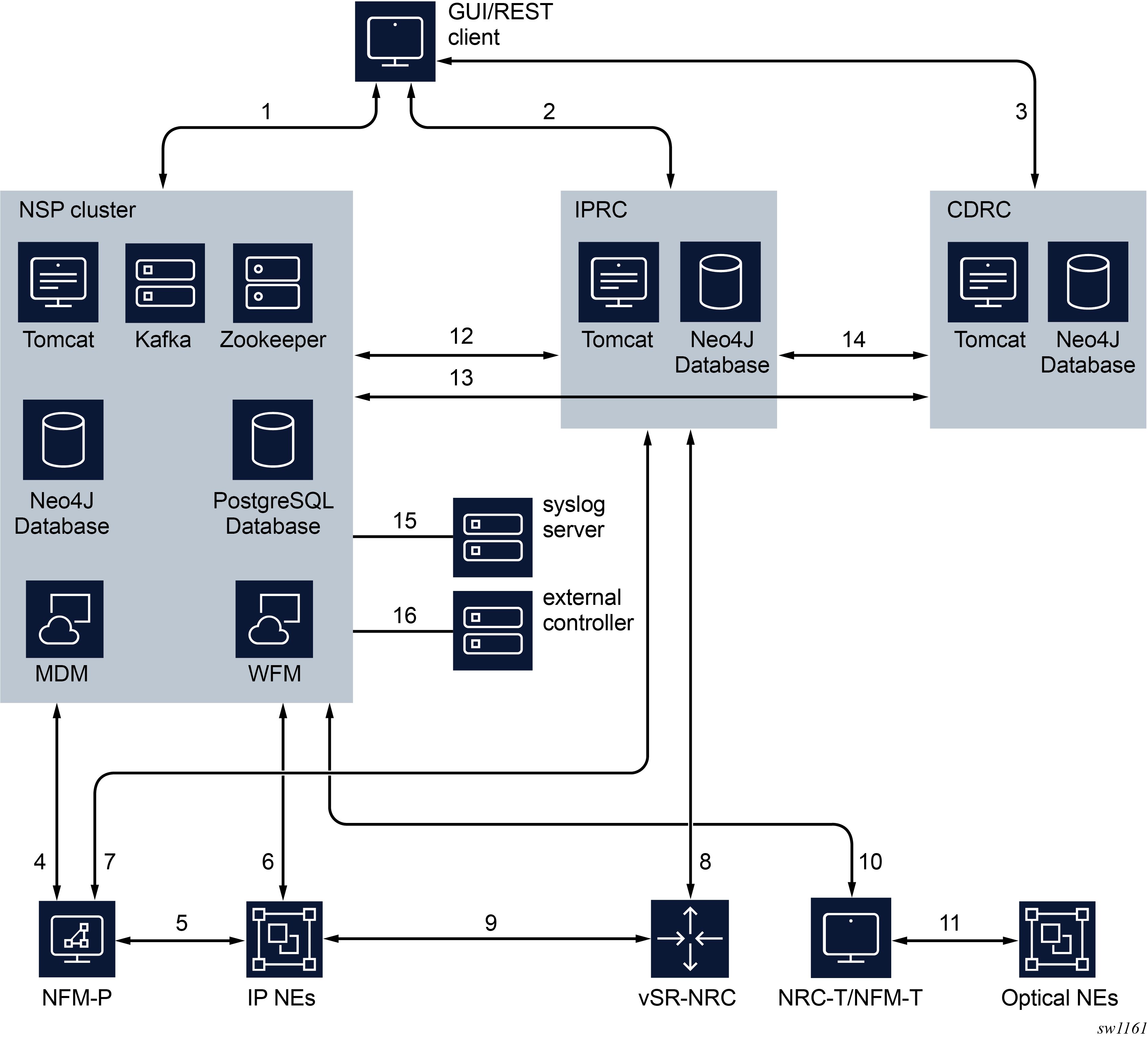
Figure 2 illustrates the NRC-P.
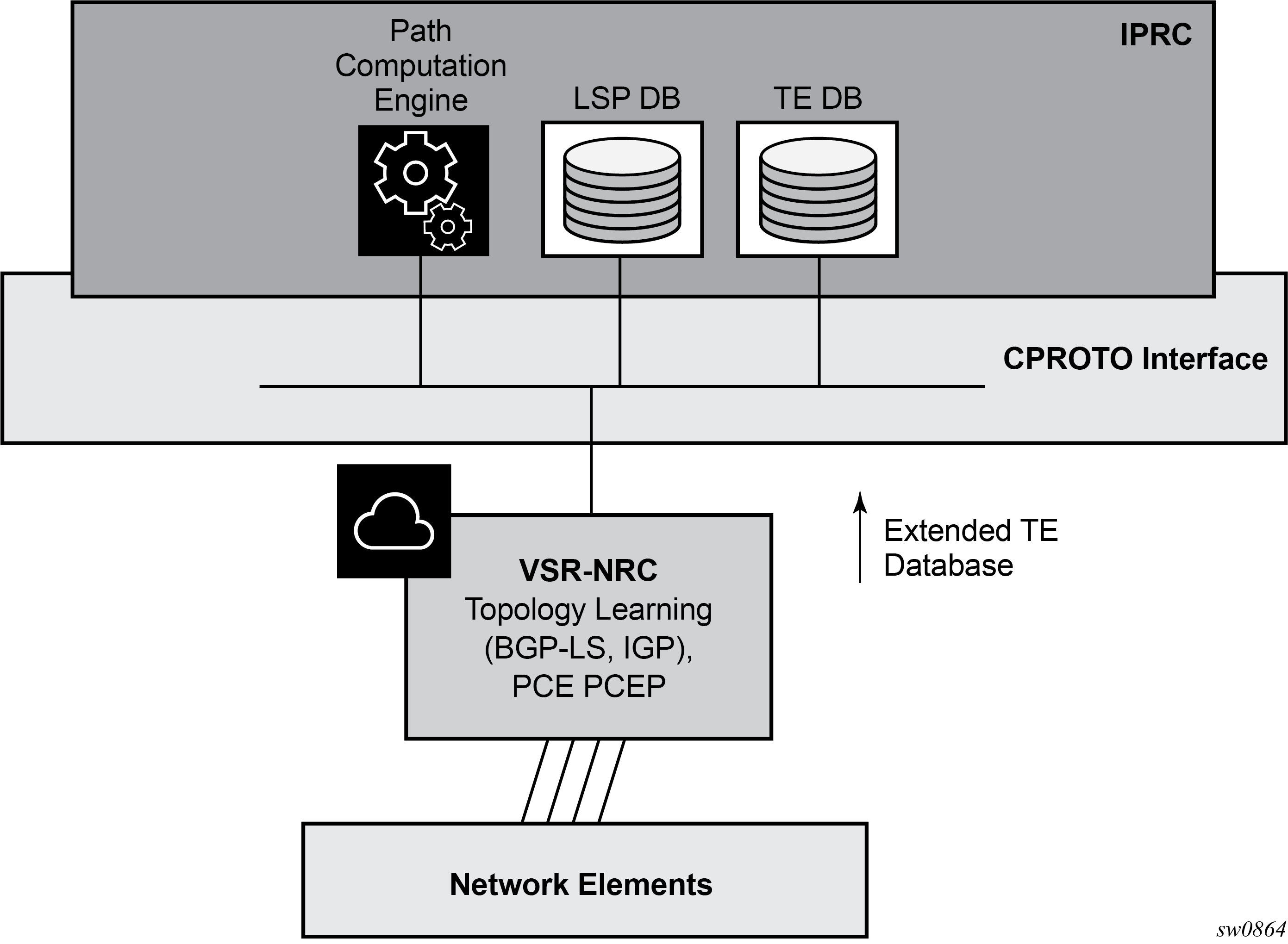
The NRC-P has the following architecture:
-
a single Virtual Machine (VM) handling the Java implementation of an MPLS path computation engine, a Traffic Engineering (TE) graph database (TE-DB), and an LSP database (LSP-DB). This is part of the IPRC as shown in Figure 1.
-
a single VM running a SR OS image handles the functions of topology discovery of multiple IGP instances and areas via IGP or BGP-LS and the PCE PCEP functions. This is referred to as the VSR Network Resource Controller (VSR-NRC).
-
a plug-in adapter using the Nokia CPROTO interface, providing reliable, TCP-based message delivery between VSR-NRC and the IPRC. The plug-in adapter implements a compact encoding/decoding (codec) function for the message content using Google ProtoBuf. Google ProtoBuf also provides for automatic C++ (VSR-NRC side) and Java (IPRC side) code generation to process the exchanged message content.
The VSR-NRC implements a PCEP PCE function, an OpenFlow controller, a BMP station database, a Route Origination module, and a TE database populated using IGP and BGP-LS.
The NRC-P module of the NSP and the VSR-NRC communicate using a reliable proprietary TCP-based channel called CPROTO. The NRC-P module acts as the server side, it is the module which always initiates the establishment of the CPROTO session toward the VSR-NRC.
The message data within the CPROTO channel is encoded and serialized using Google Protocol Buffers (PROTOBUF).
The VSR-NRC implements an NSP-Proxy module that manages all databases and channels used in the communications with the NRC-P. The NSP-Proxy opens a dedicated UDP port number 4199 for this communication and operates as the client side. This port is managed by the NSP-PROXY.
- PCEP
- OPEN_FLOW
- BGP_LS (covers topology discovered using BGP-LS and IGP)
- BMP_STATION
- ROM_SRTE (Route Origination Module for BGP families sr-policy-ipv4 and sr-policy-ipv6)
- ROM_IPV4/V6 (BGP families IPv4 and IPv6)
- ROM_FLOSPEC (BGP families flowspec-ipv4 and flowspec-ipv6)
- ROM_LABELV4/V6 (BGP families label-ipv4 and label-ipv6)
- Global Health and Notification
The NRC-P, via the VSR-NRC, uses PCEP to communicate with its clients, referred to as PCE Clients (PCCs). Each router acting as a PCC initiates a PCEP session to the PCE in its domain.
When the user enables PCE control for one or more segment routing or RSVP-TE LSPs, the PCE owns the path updating and periodic re-optimization of the LSP. In this case, the PCE acts in an active stateful role. The PCE can also act in a stateful passive role for other LSPs on the router by discovering them and taking into account their resource consumption when computing the path for the LSPs it has control ownership of.
The following is a high-level description of the PCE and PCC capabilities:
-
base PCEP implementation, per RFC 5440
-
active and passive stateful PCE LSP update, as per RFC 8231, Path Computation Element Communication Protocol (PCEP) Extensions for Stateful PCE
-
delegation of LSP control to PCE
-
synchronization of the LSP database (LSP-DB) with network elements for PCE-controlled LSPs and network element-controlled LSPs
-
support for the RSVP-TE P2P LSP type
-
support for the SR-TE P2P LSP type, as per draft-ietf-pce-segment-routing-08, PCEP Extensions for Segment Routing
-
support for PCC-initiated LSPs, as per RFC 8231, Path Computation Element Communication Protocol (PCEP) Extensions for Stateful PCE
-
support for PCE-initiated LSPs, as per RFC 8281, PCEP Extensions for PCE-initiated LSP Setup in a Stateful PCE Model
-
support for LSP path diversity across different LERs using extensions to the PCE path profile, as per draft-alvarez-pce-path-profiles
-
support for LSP path bidirectionality constraints using extensions to the PCE path profile, as per draft-alvarez-pce-path-profiles