The network topology in Figure 1 depicts an example of link removal or failure.
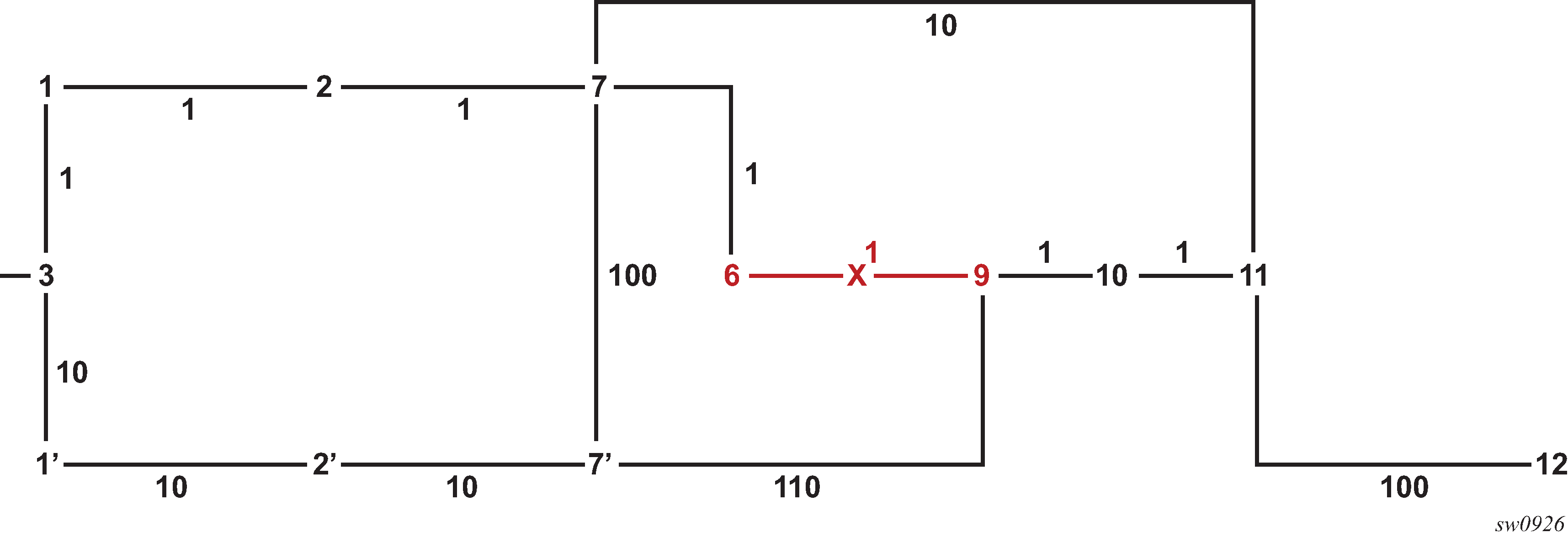
The micro-loop avoidance algorithm performs the following steps in the network topology example in Figure 1.
Link 6-9 is removed or fails.
Router 3 detects a single link event and runs main and LFA SPFs.
all nodes downstream of the removed link in the Dijkstra tree see a next-hop change: nodes 9, 10, 11, and 12
plus nodes 10, 11, and 12 are no longer downstream of node 9
all nodes upstream of the removed link see no route change: nodes 1, 2, 7, and 6
nodes 1', 2', and 7' are not using node 6 or 9 as parent nodes and are therefore are not impacted by the link removal event
For each impacted node, the algorithm computes and activates a loop-free SR tunnel to the farthest node in the shortest path that did not see a next-hop change, and then uses the adjacency SIDs to reach destination node.
For SR IS-IS tunnel of node 12, push SID of node 7 and then SIDs of adjacencies 7-11 and 11-12.
Similar to P-Q set calculation in TI-LFA, but the P node is defined as the farthest node in the shortest path to the destination in the new topology with no next-hop change.
The maximum number of labels used for the P-Q set is determined as follows.
If TI-LFA is enabled, use the value of max-sr-frr-labels.
If TI-LFA is disabled, use the value of 3 that matches the maximum value of TI-LFA parameter max-sr-frr-labels.
In both cases, this value is passed to MPLS for checking against parameter max-sr-label [additional-frr-labels] for all configured SR-TE LSPs and SR-TE LSP templates.
A future implementation compresses the path from the P node to the destination using an extra Q node calculation.
The path to the P node may travel over an RSVP-TE LSP used as an IGP shortcut. In this case, the RSVP-TE LSP must have CSPF enabled to avoid churn in IGP and to avoid micro-loop in the path of the RSVP control plane messages that are generated following the convergence of IGP, because the next hop in the ERO is looked up in the routing table.
When SR-LDP stitching is enabled and the path to the P node or the path between the P and Q nodes is partly on the LDP domain, no loop-free SR tunnel is programmed and IGP programs the new next hop or hops.
The same method applies to a metric increase of link 6-9 that causes traffic to move away from that link; for example, a metric change from 1 to 200.