Pseudowires are established between the remote PE and each dual-homed PE. The remote PE can receive traffic on either pseudowire, but only sends on the one to the designated forwarder. This creates an active/standby pair of pseudowires. At most, one standby pseudowire is established; this being determined using the tie-breaking rules defined in the multi-homing draft. This topology requires each PE to have a different VE ID.
A dual-homed, active/standby pseudowires topology example is shown in Figure 1.
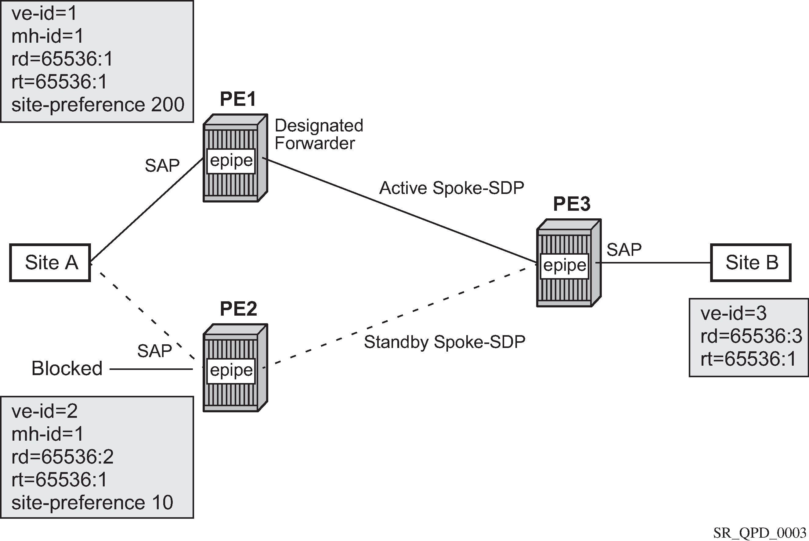
An Epipe with BGP VPWS enabled is configured on each PE. Site A is dual-homed to PE1 and PE2 with the remote PE (PE3) connecting to site B. An Epipe service is configured on each PE in which there is a SAP connecting to the local site.
The pair of dual-homed PEs perform a designated forwarder election, which is influenced by configuring the site-preference. The winner, PE1 (based on its higher site-preference) becomes the active switch for traffic sent to and from site A, while the loser, PE2, blocks its connection to site A. Pseudowires are signaled using BGP between PE1 and PE3, and between PE2 and PE3. There is no pseudowire between PE1 and PE2; this is achieved by configuration. The active/standby pseudowires on PE3 are part of an endpoint automatically created in the Epipe service.
Traffic is sent and received on the pseudowire connected to the designated forwarder, PE1.