For 7450 ESS or 7750 SR, ATM virtual trunk (VT) implements a transparent trunking of user and control traffic between two ATM switches over an ATM pseudowire. Figure 1 shows ATM 2 and ATM 3 switches that appear as if they are directly connected over an ATM link. Control traffic includes PNNI signaling and routing traffic.
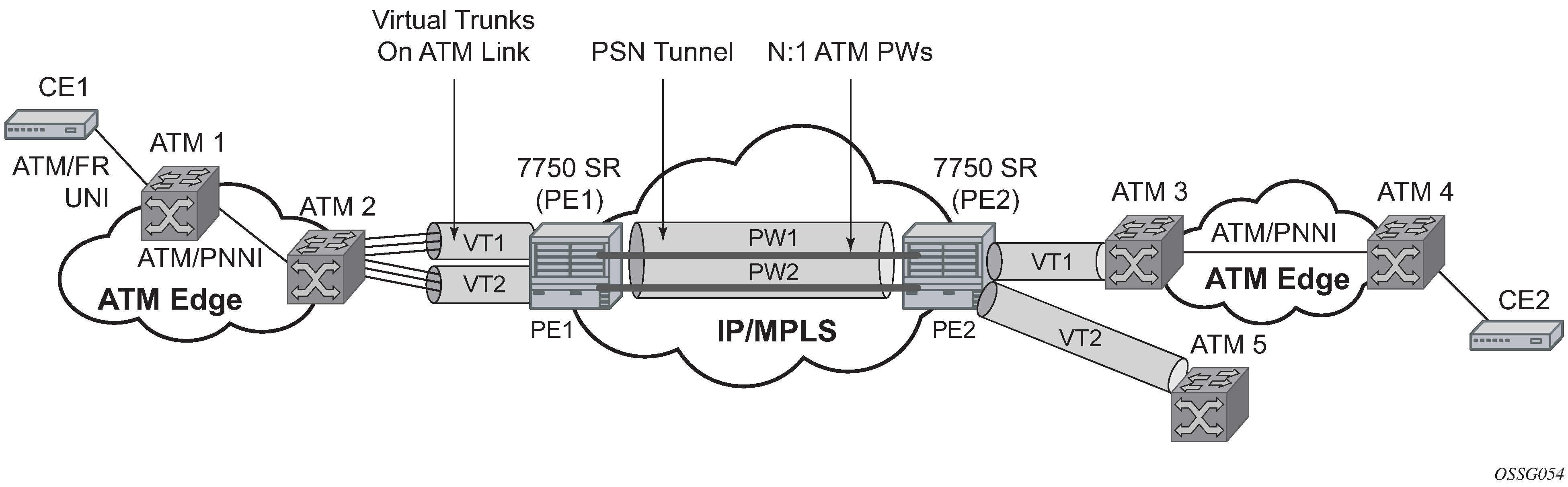
The VT SAP on a PE is identified by a tuple (port, VPI-range) meaning that all cells arriving on the specified port within the specified VPI range are fed into a single ATM pseudowire for transport across the IP/MPLS network. A user can configure the whole ATM port as a VT and does not need to specify a VPI range. No VPI/VCI translation is performed on ingress or egress. Cell order is maintained within a VT. As a special case, the two ATM ports could be on the same PE node.
By carrying all cells from all VPIs making up the VT in one pseudowire, a solution is provided that is robust; for example, black holes on some VPIs but not others. The solution is also operationally efficient because the entire VT can be managed as a single entity from the Network Manager (single point for configuration, status, alarms, statistics, and so on).
ATM virtual trunks use PWE3 N:1 ATM cell mode encapsulation to provide a cell-mode transport, supporting all AAL types, over the MPLS network. Cell concatenation on a pseudowire packet is supported. The SDP can be an MPLS or a GRE type.
The ATM pseudowire is initiated using Targeted LDP (T-LDP) signaling (defined in RFC 4447, Pseudowire Setup and Maintenance using LDP). In this application, there is no ATM signaling on the gateway nodes because both endpoints of the MPLS network are configured by the network operator. ATM signaling between the ATM nodes is passed transparently over the VT (along with user traffic) from one ATM port on a PE to another ATM port on a remote (or the same) SR PE.