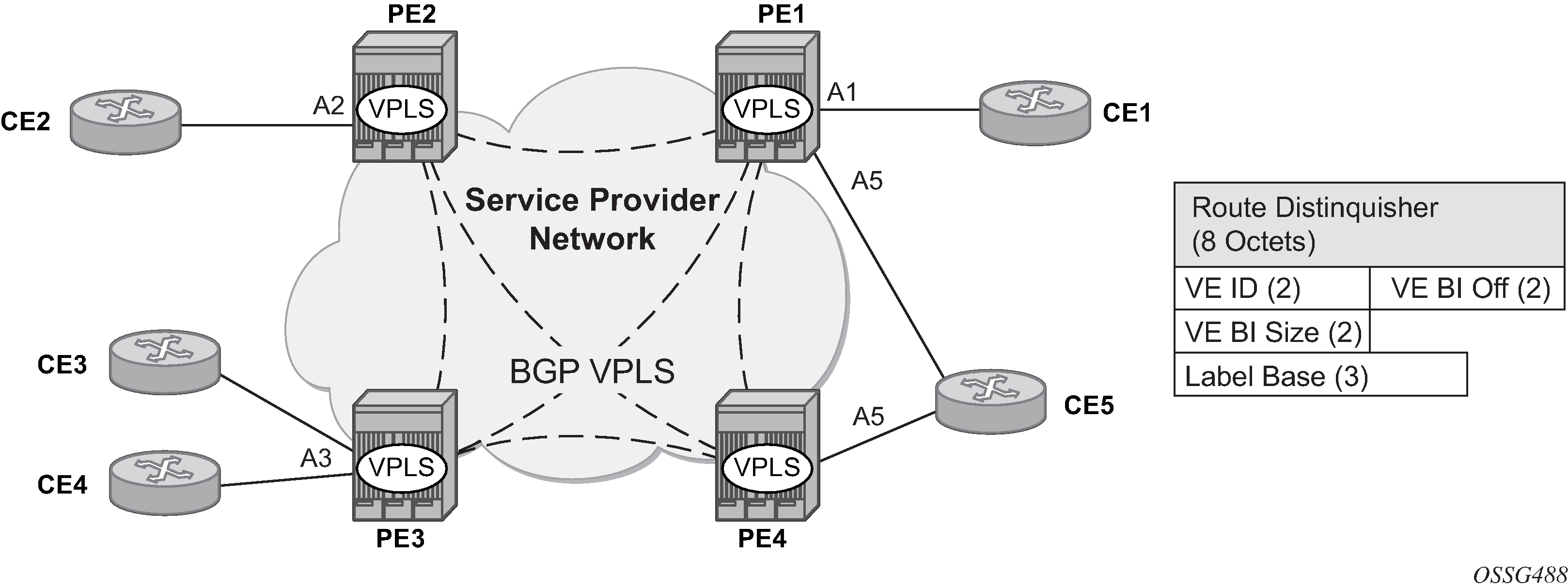
The Nokia BGP VPLS solution, compliant with RFC 4761, Virtual Private LAN Service (VPLS) Using BGP for Auto-Discovery and Signaling, is described in this section.

Figure 1 shows the service representation for BGP VPLS mesh. The major BGP VPLS components and the deltas from LDP VPLS with BGP AD are as follows:
Data plane is identical with the LDP VPLS solution; for example, VPLS instances interconnected by pseudowire mesh. Split horizon groups may be used for loop avoidance between pseudowires.
Addressing is based on a 2-byte VE-ID assigned to the VPLS instance.
BGP-AD for LDP VPLS: 4-byte VSI-ID (system IP) identifies the VPLS instance.
The target VPLS instance is identified by the Route Target (RT) contained in the MP-BGP advertisement (extended community attribute).
BGP-AD: a new MP-BGP extended community is used to identify the VPLS. RT is used for topology control.
Auto-discovery is MP-BGP based; the same AFI, SAFI is used as for LDP VPLS BGP-AD.
The BGP VPLS updates are distinguished from the BGP-AD updates based on the value of the NLRI prefix length: 17 bytes for BGP VPLS, 12 bytes for BGP-AD.
BGP-AD NLRI is shorter because there is no need to carry pseudowire label information as T-LDP does the pseudowire signaling for LDP VPLS.
Pseudowire label signaling is MP-BGP based. Therefore, the BGP NLRI content also includes label-related information; for example, block offset, block size, and label base.
LDP VPLS: target LDP (T-LDP) is used for signaling the pseudowire service label.
The Layer 2 extended community proposed in RFC 4761 is used to signal pseudowire characteristics; for example, VPLS status, control word, and sequencing.