EVPN OISM supports multi-homed multicast sources and receivers.
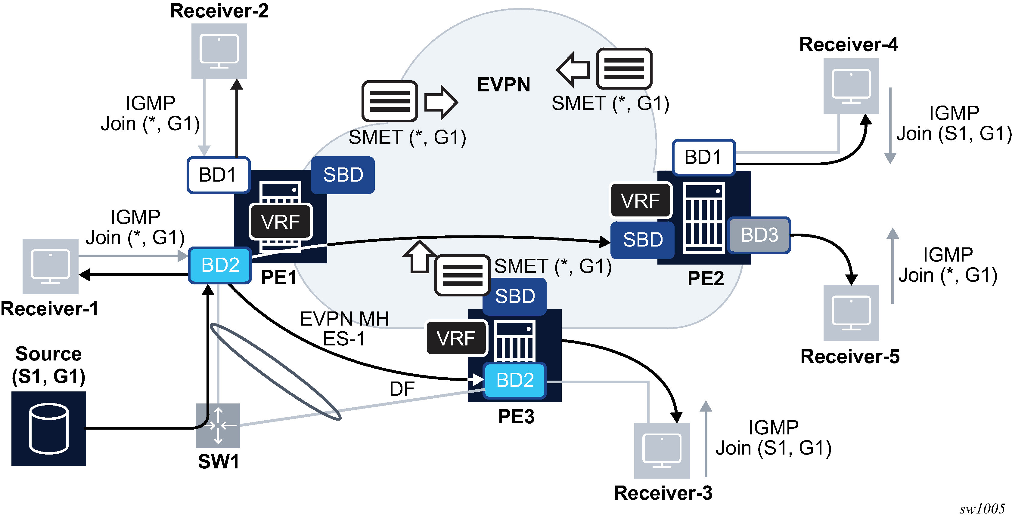
While MVPN requires complex UMH (Upstream Multicast Hop) selection procedures to provide multi-homing for sources, EVPN simply reuses the existing EVPN multi-homing procedures. Figure 1 illustrates an example of a multi-homed source that makes use of EVPN All-Active multi-homing.

The source S1 is attached to a switch SW1 that is connected via single LAG to PE1 and PE2, a pair of EVPN OISM PEs. PE1 and PE2 define Ethernet Segment ES-1 for SW1, where ES-1 is all-active in this case (single-active multi-homing being supported too). Even in case of all-active, the multicast flow for (S1,G1) is only sent to one OISM PE, and the regular all-active multi-homing procedures (Split-Horizon) make sure that PE3 does not send the multicast traffic back to SW1. This is true for EVPN-MPLS and EVPN-VXLAN BDs.
Convergence, in case of failure, is very fast because the downstream PEs, for example, PE2, advertise the SMET route for (*,G1) with the SBD route target and it is imported by both PE1 and PE3. In case of failure on PE2, PE3 already has state for (*,G1) and can forward the multicast traffic immediately.
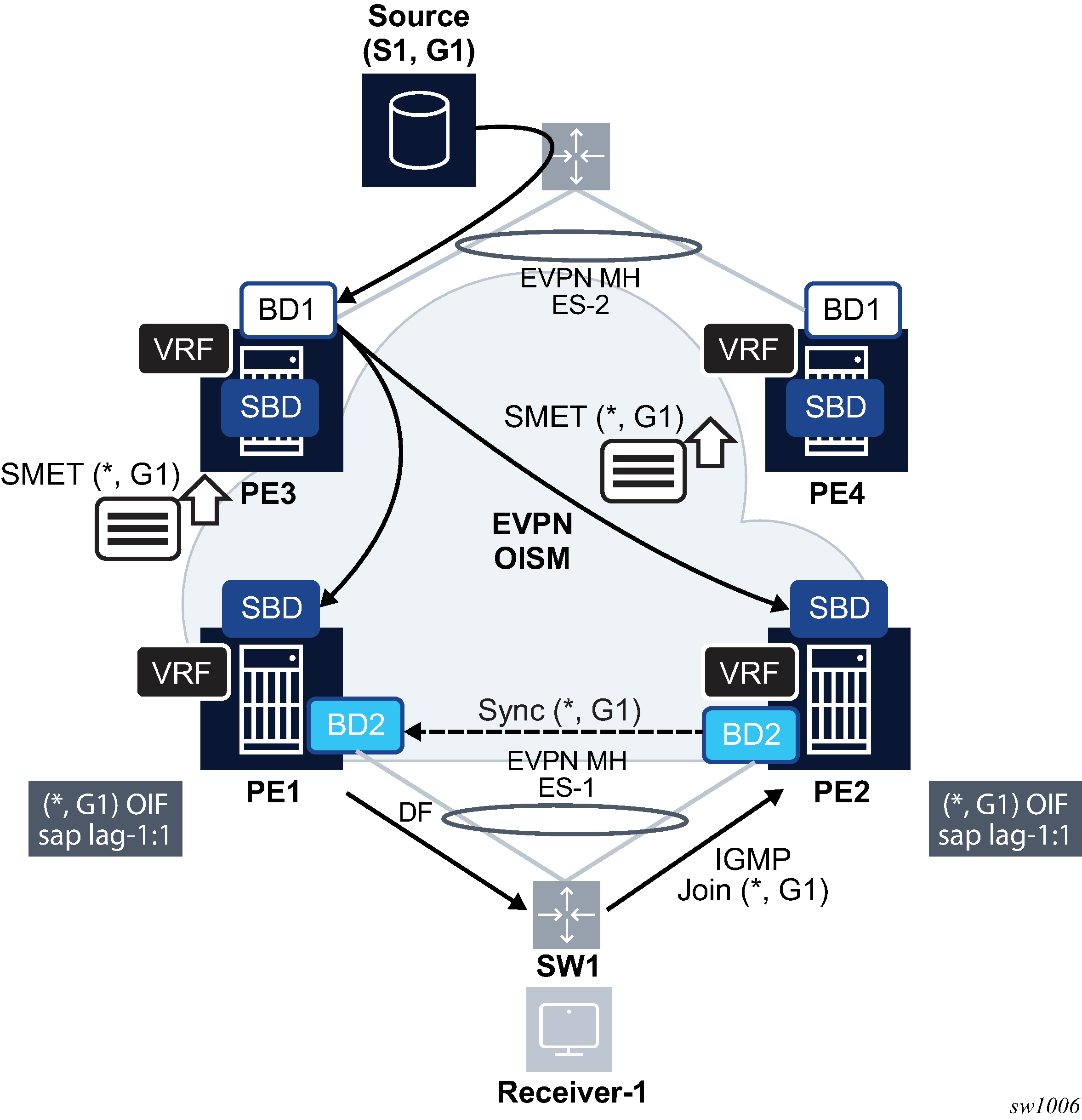
EVPN OISM also supports multi-homed receivers. Figure 2 illustrates an example of multi-homed receivers.

Multi-homed receivers as depicted in Figure 2, require the support of multicast state synchronization on the multi-homing PEs to avoid blackholes. As an example, consider that SW1 hashes an IGMP join (*,G1) to PE2, and PE2 adds the ES-1 SAP to the OIF list for (*,G1). Consider PE1 is the ES-1 DF. Unless the (*,G1) state is synchronized on PE1, the multicast traffic is pulled to PE2 only and then discarded. The state synchronization on PE1 pulls the multicast traffic to PE1 too, and PE1 forwards to the receiver using its DF SAP.
In SR OS, the IGMP/MLD-snooping state is synchronized across ES peers using EVPN Multicast Synch routes, as specified in draft-ietf-bess-evpn-igmp-mld-proxy.
The same mechanism must be used in all the PEs attached to the same Ethernet Segment. MCS takes precedence when both mechanisms are simultaneously used.
The use of Multi-Chassis Synchronization (MCS) protocol is not supported in VPLS services in OISM mode or evpn-proxy mode.
EVPN Multicast Synch routes are supported as specified in draft-ietf-bess-evpn-igmp-mld-proxy for OISM services. They use EVPN route types 7 and 8, and are known as the Multicast Join Synch and Multicast Leave Synch routes, respectively.
When a PE that is attached to an EVPN Ethernet Segment receives an IGMP or MLD join, it creates multicast state and advertises a Multicast Join Synch route so that the peer ES PEs can synchronize the state. Similarly, when a PE in the Ethernet Segment receives a leave message, it advertises a Multicast Leave Synch route so that all the PEs in the Ethernet Segment can synchronize the Last Member Query procedures.
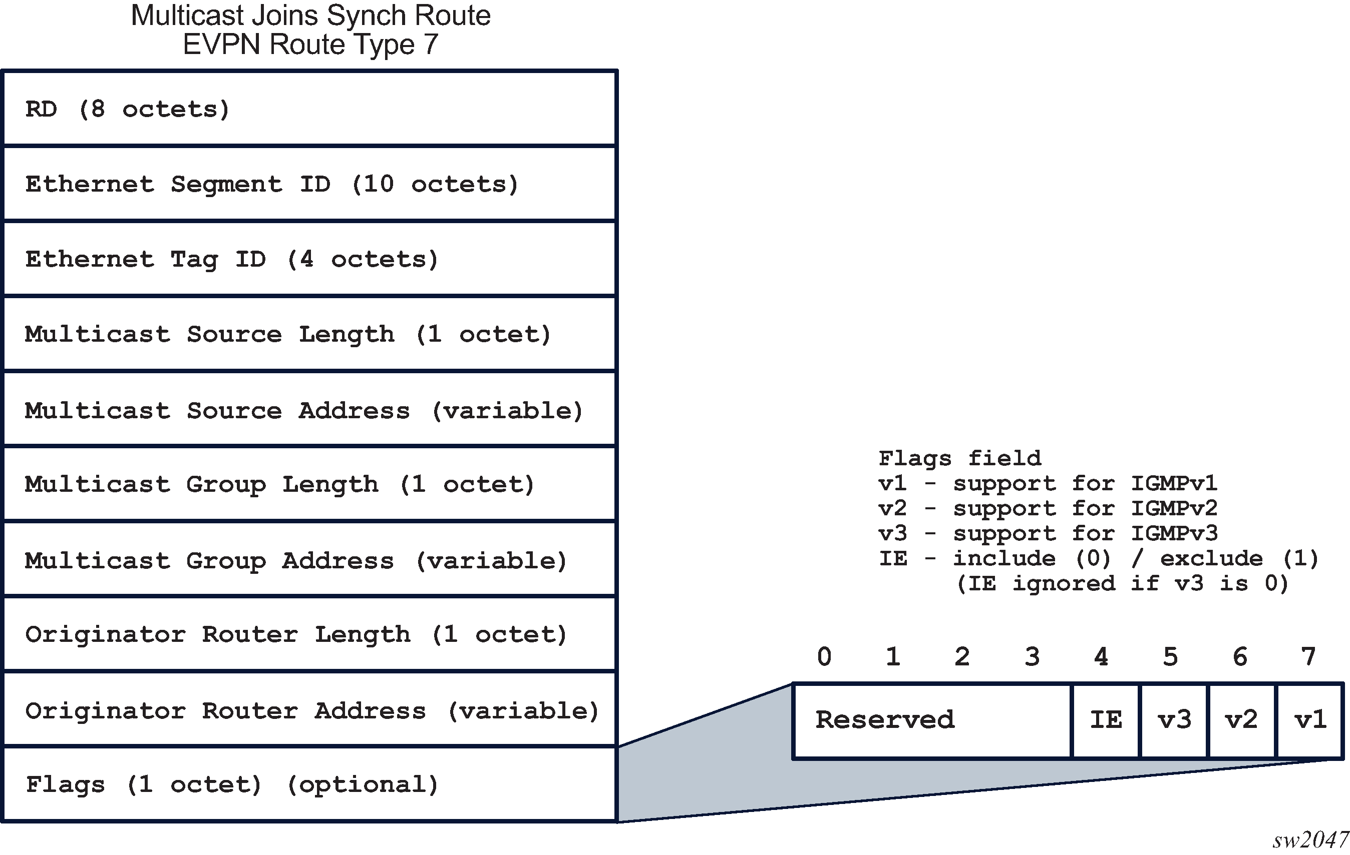
The Multicast Join Synch route or EVPN route type 7 is similar to the SMET route, but also includes the ESI. The Multicast Join Synch route indicates the multicast group that must be synchronized in all objects of the Ethernet Segment. Figure 3 depicts the format of the Multicast Join Synch route.

In accordance with draft-ietf-bess-evpn-igmp-mld-proxy, the following rules pertain.
All fields except for the Flags are part of the route key for BGP processing purposes.
Synch routes are resolved by BGP auto-bind resolution, as any other service route.
The Flags are advertised and processed based on the received igmp or mld report that triggered the advertisement of the route (this includes the versions for IGMP or MLD and Include/Exclude bit for IGMPv3).
The Route Distinguisher (RD) is the service RD.
This route is only distributed to the ES peers - it is advertised with the ES-import route target, which limits its distribution to ES peers only.
In addition, the route is sent with only one EVI-RT extended community. The EVI-RT EC does not use a route target type/sub-type, therefore, it does not affect the distribution of the route, for example, it is not considered for route target constraint filtering; only the ES-import route target is. However, its value is still taken from the configured service route target or evi auto-derived route target.
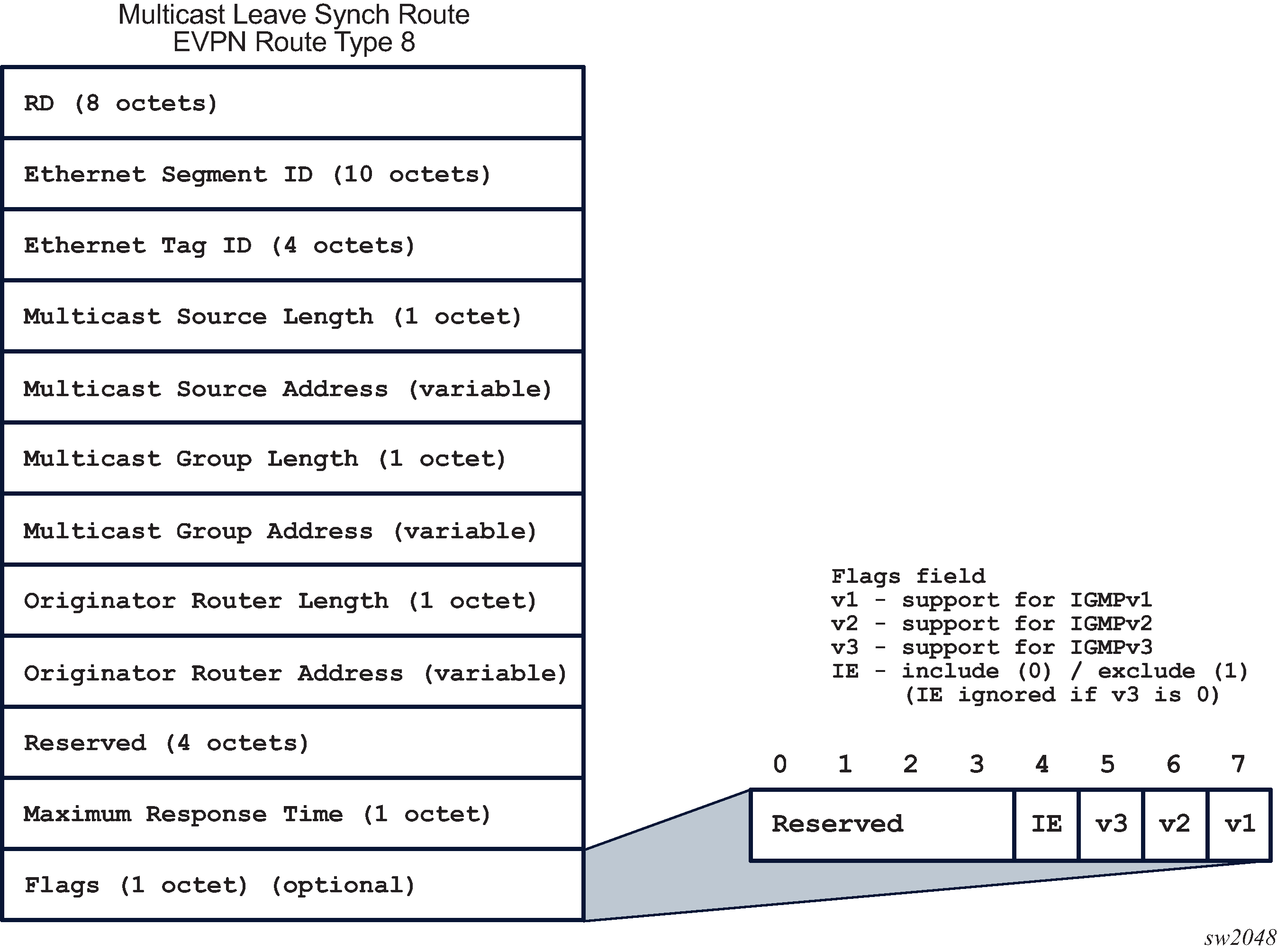
The Multicast Leave Synch route or EVPN route type 8 indicates the multicast group Leave states that must be synchronized in all objects of the Ethernet Segment. Figure 4 depicts the format of the Multicast Leave Synch route.

In accordance with draft-ietf-bess-evpn-igmp-mld-proxy, the following rules pertain.
All fields except for the Flags, the Maximum Response Time and ‟reserved” field are part of the route key for BGP processing purposes.
Synch routes are resolved by BGP auto-bind resolution, as any other service route.
The Flags are generated based on the version of the leave message that triggered the advertisement of the route.
As with the Multicast Join Synch route, this is a service level route sent with one ES-import route target and one EVI-RT EC. RD, Flags, ES-import and EVI-RT EC are advertised and processed in the same way as for the Multicast Join Synch route.
The EVI-RT is automatically added to the routes type 7 and 8, depending on the type of route target being configured on the service.
If the service is configured with target:2byte-asnumber:ext-comm-val as route target, an EVI-RT type 0 is automatically added to routes type 7 and 8. No route target (other than the ES-import route target) is added to the route.
If the service is configured with target:ip-addr:comm-val as route target, an EVI-RT type 1 is automatically added to routes type 7 and 8. No route target (other than the ES-import route target) is added to the route.
If the service is configured with target:4byte-asnumber:comm-val as route target, an EVI-RT type 2 is automatically added to routes type 7 and 8. No route target (other than the ES-import route target) is added to the route.
If auto-derived service RTs are used in the service, the corresponding operating route target is used as the EVI-RT.
EVI-RT type 3 is not supported (type 3 is specified in draft-ietf-bess-evpn-igmp-mld-proxy).
In general, vsi-import and vsi-export must not be used in OISM mode services or when the Multicast Synch routes are used. Using vsi-import or vsi-export policies instead of the route target command or the EVI-derived route target leads to issues when advertising and processing the Multicast Synch routes.
The following are additional considerations about the Multicast Synch routes.
The routes are advertised without the need to configure any command as long as igmp-snooping or mld-snooping are enabled on an R-VPLS in OISM mode attached to a regular or virtual Ethernet Segment.
The reception of Multicast Join or Leave Synch routes triggers the synchronization of states and the associated procedures in draft-ietf-bess-evpn-igmp-mld-proxy.
Upon receiving a Leave message, the triggered Multicast Synch route encodes the configured Last Member Query interval times robust-count (LMQ ✕ robust-count) in the Maximum Response Time field. The local PE expires the multicast state after the usual time plus an additional time that accounts for the BGP propagation to the remote ES peers and can be configured with the command config>service>system>bgp-evpn>multicast-leave-sync-propagation number. This timer should be configured the same in all the PEs attached to the same ES.