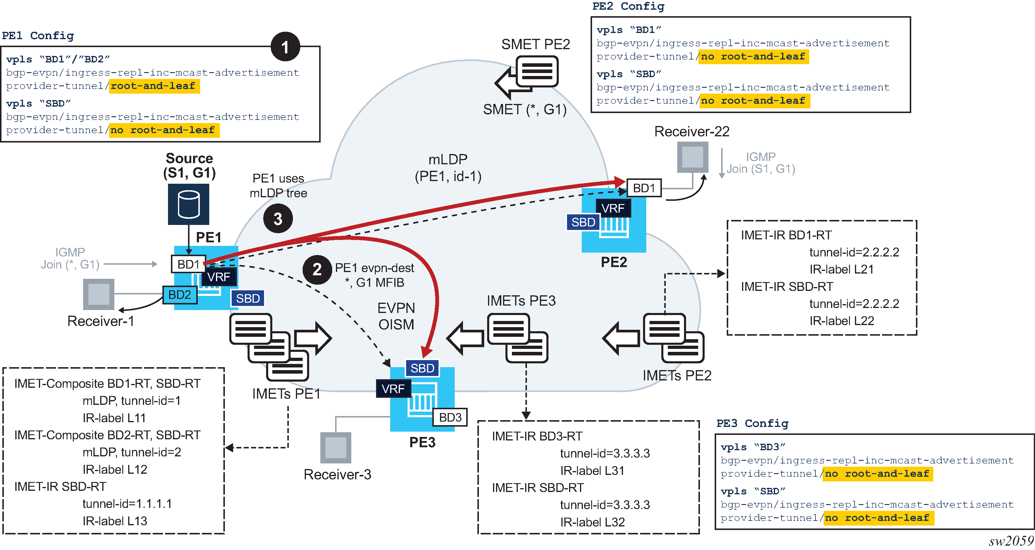
Figure 1 illustrates an example of the OISM procedures with mLDP trees.

Consider three PEs, PE1, PE2, and PE3, attached to BD1/BD2, BD1, and BD3 respectively, as in Figure 1. Assume that the source S1 is connected to BD1 in PE1. PE2 and PE3 are leaf PEs, because they have receivers but no sources. In this example:
BD and SBD services must be configured for provider tunnel as follows.
To have PE1 sending multicast traffic in P2MP mLDP tunnels on BD1 and BD2, both BDs are configured as provider-tunnel inclusive root-and-leaf. They are also configured with ingress-repl-inc-mcast-advertisement. The following is an example configuration of BD1 in PE1.
*A:PE-1>config>service>vpls# info
----------------------------------------------
            allow-ip-int-bind
            exit
            bgp
            exit
            bgp-evpn
                evi 1
                ingress-repl-inc-mcast-advertisement // default value
                mpls bgp 1
                    auto-bind-tunnel
                        resolution any
                    exit
                    no shutdown
                exit
            exit
            provider-tunnel
                inclusive
                    owner bgp-evpn-mpls
                    root-and-leaf
                    data-delay-interval 10
                    mldp
                    no shutdown
                exit
            exit
            igmp-snooping / mld-snooping
              no shutdown
            exit
<snip>
PE2 and PE3 BDs are configured as leaf (no root-and-leaf) as they must be able to join mLDP trees but not set up an mLDP tree themselves. It is important that these BDs are configured with the ingress-repl-inc-mcast-advertisement command that allows upstream PEs to create destinations to them.
Multicast traffic cannot use the mLDP tree unless there is an EVPN-MPLS destination in the MFIB for the multicast stream.
The SBDs in all PEs must be configured as provider-tunnel>inclusive>no root-and-leaf and ingress-repl-inc-mcast-advertisement.
When the configuration is added, the PEs create EVPN-MPLS destinations as follows, where a destination is represented as {pe, label} with ‟pe” being the IP address of the remote PE and ‟label” being the EVPN label advertised by the remote PE.
PE1 creates the following EVPN-MPLS destinations:
On BD1: {pe2,bd1-L21}, {pe2,sbd-L22}, {pe3,sbd-L32}
On BD2: {pe2,sbd-L22}, {pe3,sbd-L32}
On SBD: {pe2,sbd-L22}, {pe3,sbd-L32}
PE2 creates destinations as follows:
On BD1: {pe1,bd1-L11}, {pe1,sbd-L13}, {pe3,sbd-L32}
On SBD: {pe1,sbd-L13}, {pe3,sbd-L32}
PE3 creates destinations as follows:
On BD3: {pe1,sbd-L13}, {pe2,sbd-L22}
On SBD: {pe1,sbd-L13}, {pe2,sbd-L22}
PE2's BD1 and PE3's BD3 does not create an EVPN-MPLS destination to PE1's BD2. Also, PE3's BD3 does not create a destination to PE1's BD1. This is in spite of receiving IMET-Composite routes for those BDs with the SBD-RT, which is imported in PE2/PE3 ordinary BDs.
As an example, on BD1, PE1's IGMP process adds the EVPN-MPLS destinations {pe2,bd1-L21}, {pe3,sbd-L32} to the MFIB. The third destination {pe2,sbd-L22} is kept down because the EVPN-MPLS destination in BD1 has higher priority.
Upon receiving the SMET route from PE2, PE1 adds {pe2,bd1-L21} as OIF for the MFIB (*,G1).
In the meantime, PE2 and PE3 have joined the mLDP tree with tunnel-id 1.
When multicast to G1 is received from S1, because there is an MFIB EVPN OIF entry, the multicast traffic is forwarded. At the IOM level, PE1 replaces the MFIB EVPN destination with the P2MP tunnel with tunnel-id 1, as long as the P2MP tree is operationally up.
The multicast traffic is sent along the mLDP tree and arrives at PE2/BD1 and PE3/SBD. Then local forwarding or routing is performed in PE2 and PE3, as normally in OISM.