Based on the previously mentioned rules, the following is an example of a failure scenario. Assuming both links are active on 7750 SR #1 and the Ethernet connection to the cell site fails (most likely failure scenario because the connection would not be protected), SDP1 would go down and the secondary SAP would be used in 7750 SR #1 and 7705 SAR, as shown in Figure 1.
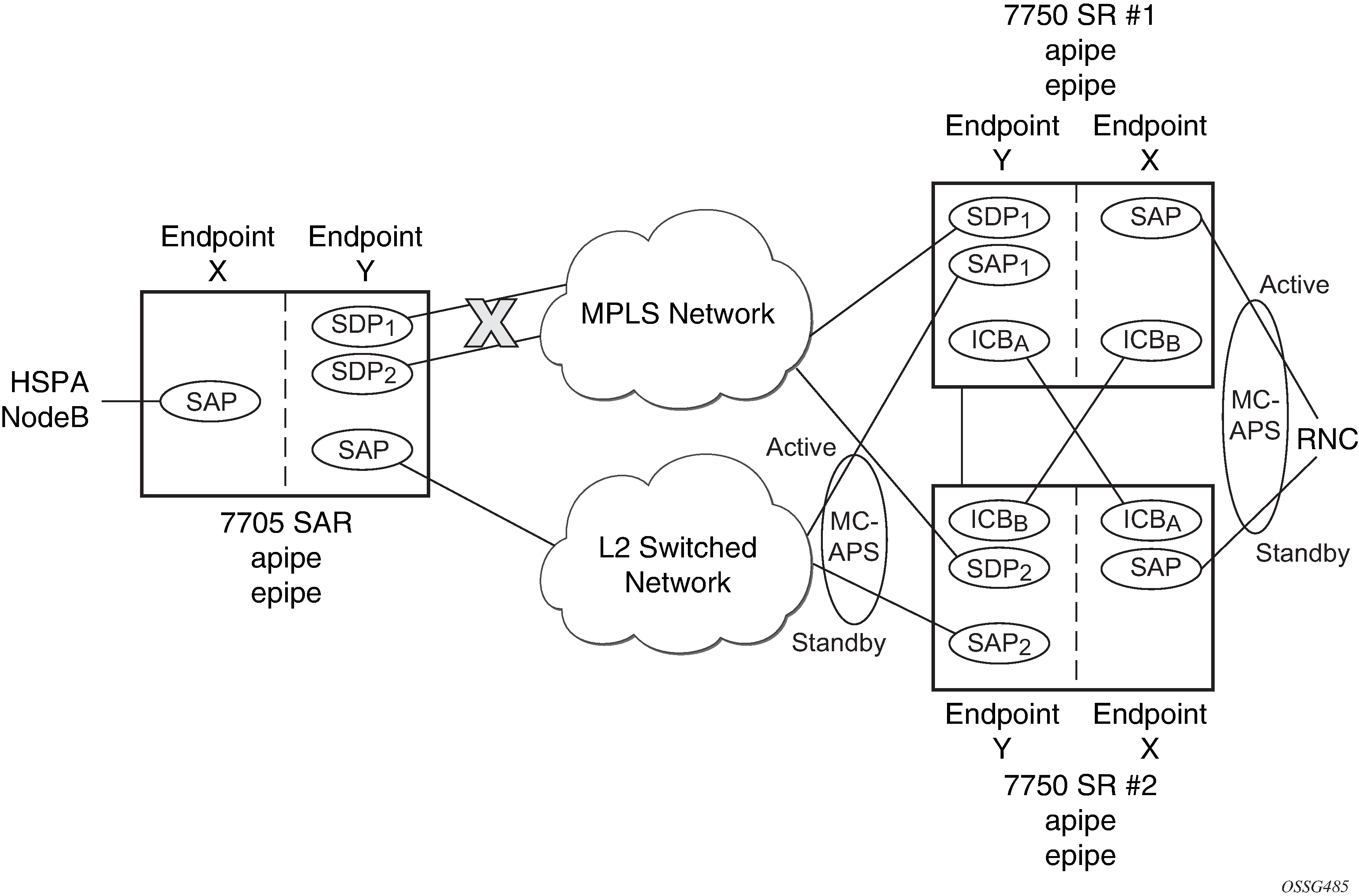
If the active link to the Layer 2 switched network was on 7750 SR #2 at the time of the failure, SAP1 would be operationally down (because the link is in standby) and ICBA would be used. Because the RNC SAP on 7750 SR #2 is on a standby APS link, ICBA would be active and it would connect to SAP2 because SDP2 is operationally down as well.
All APS link failures would be handled through the standard pseudowire status messaging procedures for the RNC connection and through standard ICB usage for the Layer 2 switched network connection.