Inter-domain VPLS refers to a VPLS deployment where sites may be located in different domains. An example of inter-domain deployment can be where different metro domains are interconnected over a Wide Area Network (Metro1-WAN-Metro2) or where sites are located in different autonomous systems (AS1-ASBRs-AS2).
Multi-chassis endpoint (MC-EP) provides an alternate solution that does not require RSTP at the gateway VPLS PEs while still using pseudowires to interconnect the VPLS instances located in the two domains. It is supported in both VPLS and PBB-VPLS on the B-VPLS side.
MC-EP expands the single chassis endpoint based on active-standby pseudowires for VPLS, shown in Figure 1.
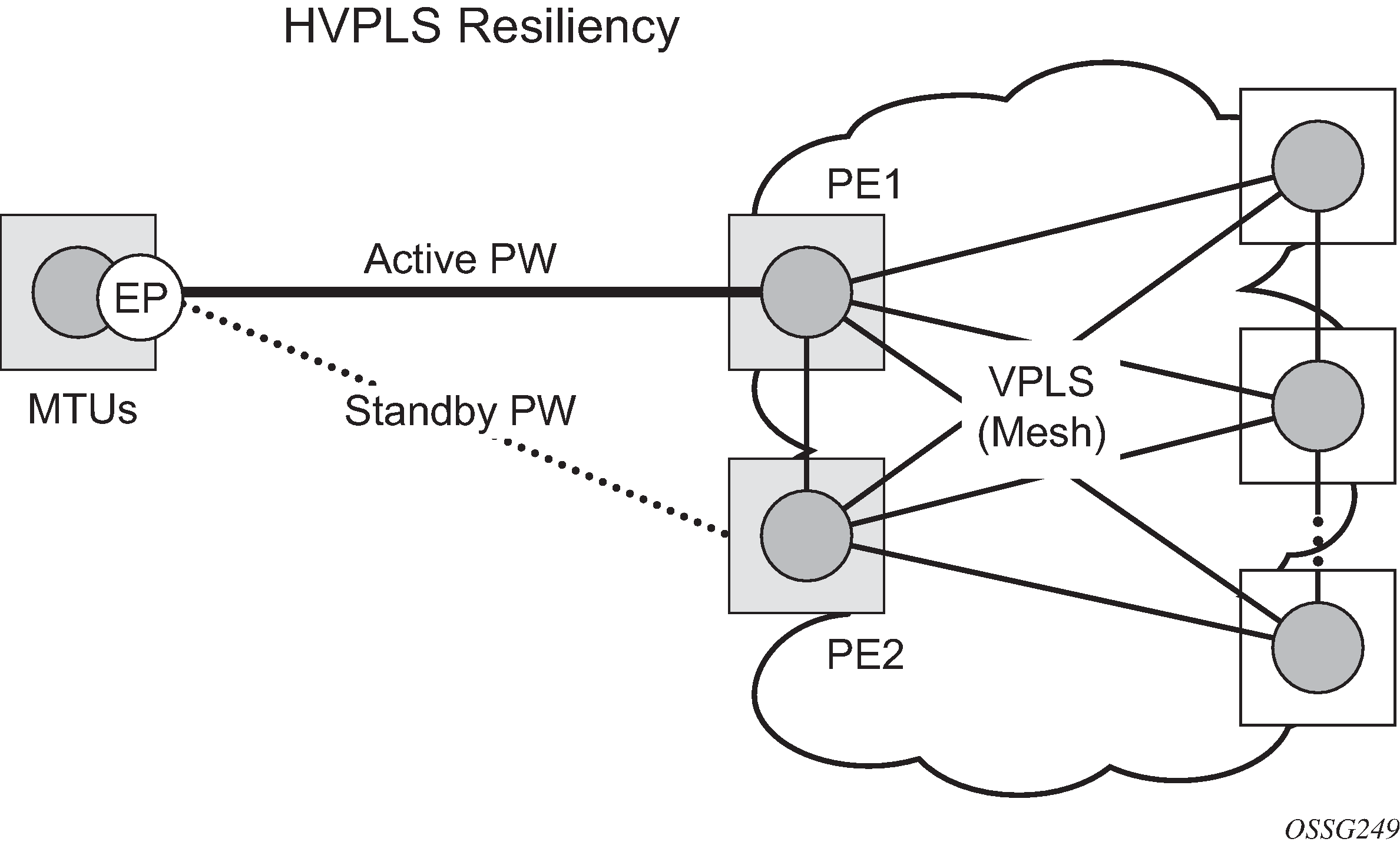
The active-standby pseudowire solution is appropriate for the scenario when only one VPLS PE (MTUs) needs to be dual-homed to two core PEs (PE1 and PE2). When multiple VPLS domains need to be interconnected, the above solution provides a single point of failure at the MTU-s. The example shown in Figure 2 can be used.
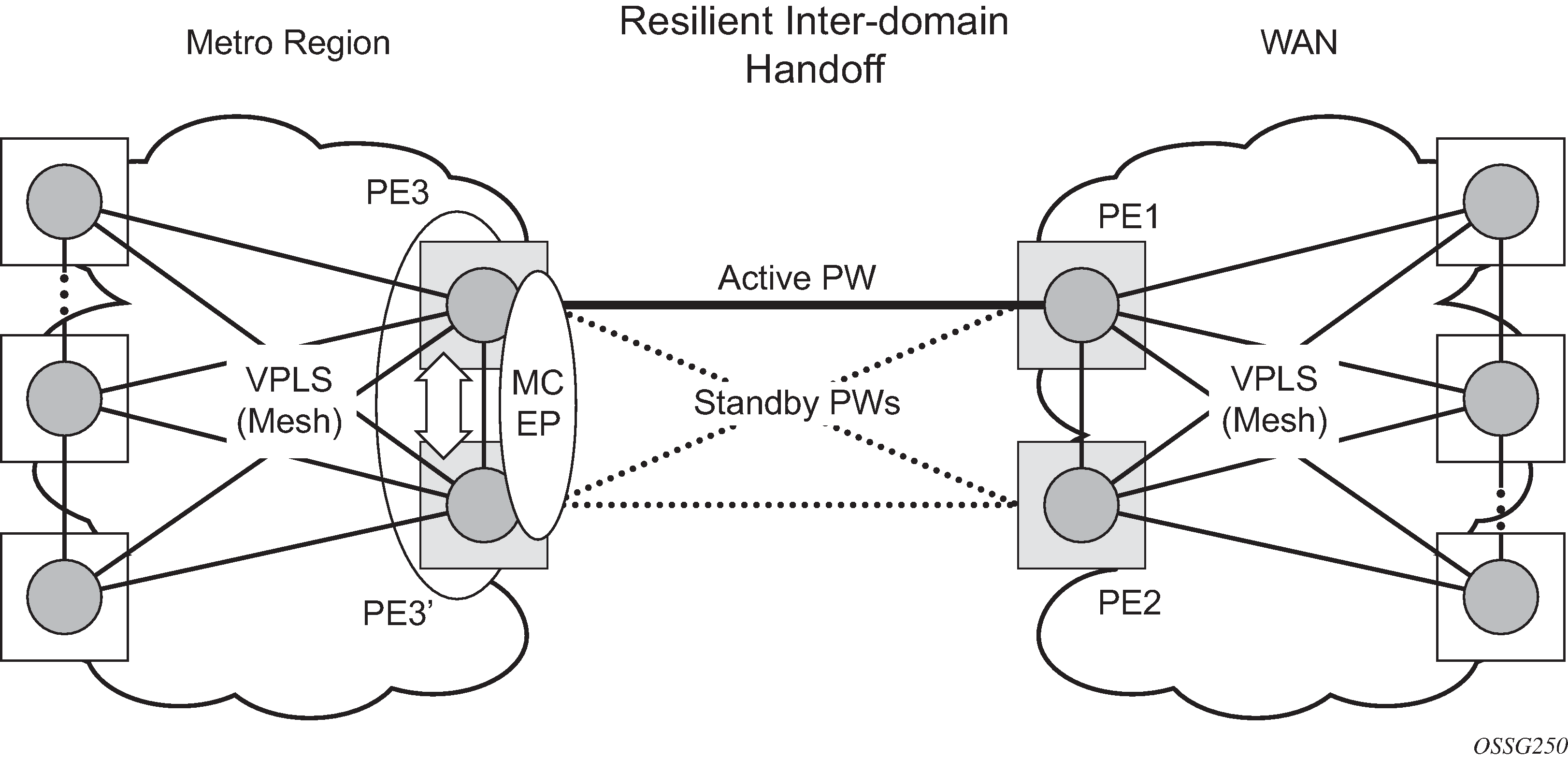
The two gateway pairs, PE3-PE3’ and PE1-PE2, are interconnected using a full mesh of four pseudowires out of which only one pseudowire is active at any time.
The concept of pseudowire endpoint for VPLS provides multi-chassis resiliency controlled by the MC-EP pair, PE3-PE3’ in this example. This scenario, referred to as multi-chassis pseudowire endpoint for VPLS, provides a way to group pseudowires distributed between PE3 and PE3 chassis in a virtual endpoint that can be mapped to a VPLS instance.
The MC-EP inter-chassis protocol is used to ensure configuration and status synchronization of the pseudowires that belong to the same MC-EP group on PE3 and PE3. Based on the information received from the peer shelf and the local configuration, the master shelf decides on which pseudowire becomes active.
The MC-EP solution is built around the following components:
Multi-chassis protocol used to perform the following functions:
Selection of master chassis.
Synchronization of the pseudowire configuration and status.
Fast detection of peer failure or communication loss between MC-EP peers using either centralized BFD, if configured, or its own keep-alive mechanism.
T-LDP signaling of pseudowire status:
Informs the remote PEs about the choices made by the MC-EP pair.Pseudowire data plane — Represented by the four pseudowires inter-connecting the gateway PEs.
Only one of the pseudowires is activated based on the primary/secondary, preference configuration, and pseudowire status. In case of a tie, the pseudowire located on the master chassis is chosen.
The rest of the pseudowires are blocked locally on the MC-EP pair and on the remote PEs as long as they implement the pseudowire active/standby status.