The scenario shown in Figure 1 is used to define the blackholing problem in PBB-VPLS using MC-EP.
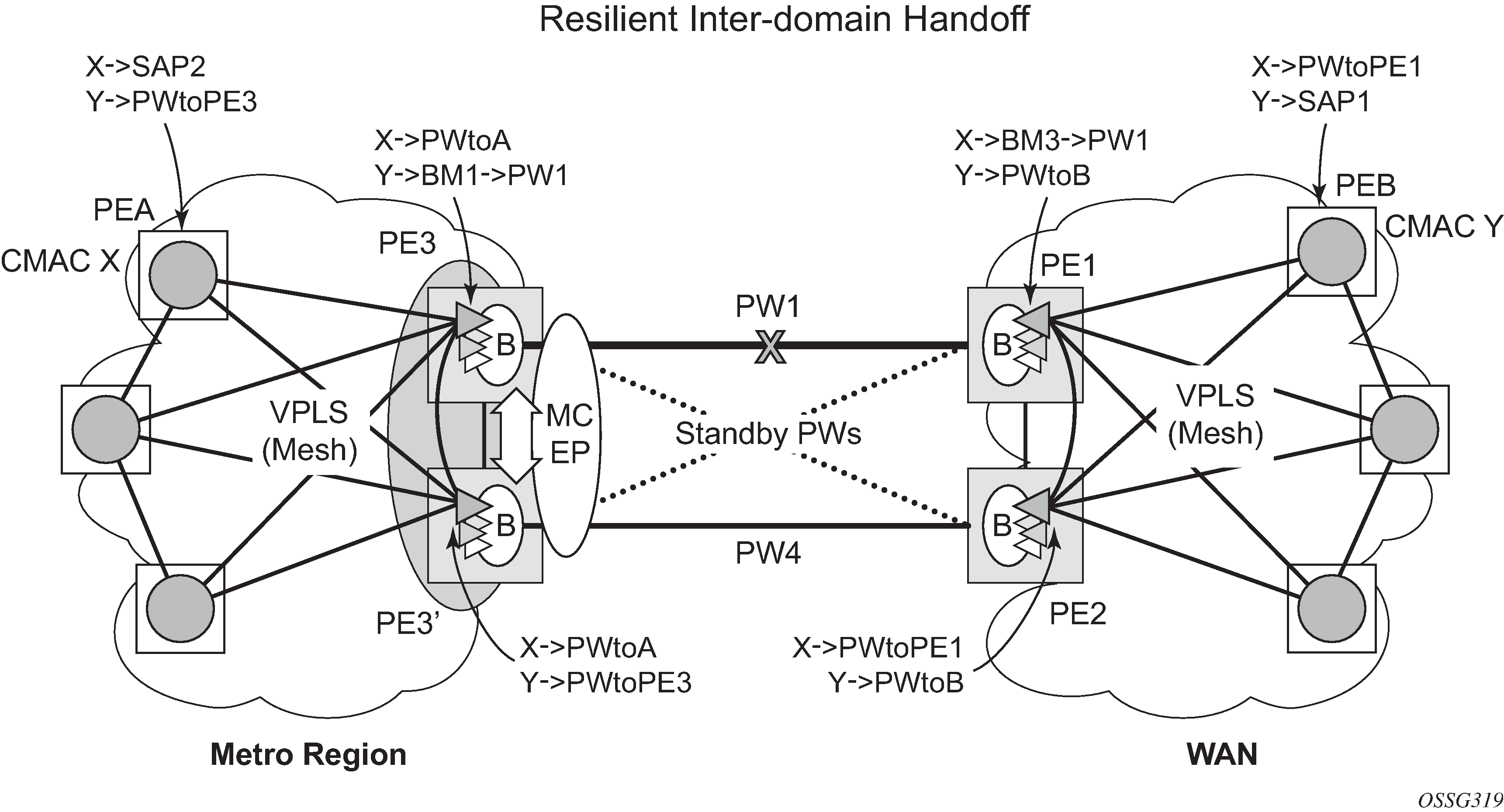
In the topology shown in Figure 1, PEA and PEB are regular VPLS PEs participating in the VPLS mesh deployed in the metro and WAN region, respectively. As the traffic flows between CEs with C-MAC X and C-MAC Y, the FDB entries in PEA, PE3, PE1 and PEB are installed. An LDP flush-all-but-mine message is sent from PE3 to PE2 to clear the B-VPLS FDBs. The traffic between C-MAC X and C-MAC Y is blackholed as long as the entries from the VPLS and I-VPLS FDBs along the path are not removed. This may take as long as 300 seconds, the usual aging timer used for MAC entries in a VPLS FDB.
A MAC flush is required in the I-VPLS space from PBB PEs to PEA and PEB to avoid blackholing in the regular VPLS space.
In the case of a regular VPLS, the following procedure is used:
PE3 sends a flush-all-from-me message toward its local blue I-VPLS mesh to PE3 and PEA when its MC-EP becomes disabled.
PE3 sends a flush-all-but-mine message on the active PW4 to PE2, which is then propagated by PE2 (propagate-mac-flush must be on) to PEB in the WAN I-VPLS mesh.
For consistency, a similar procedure is used for the B-VPLS case as shown in Figure 2.
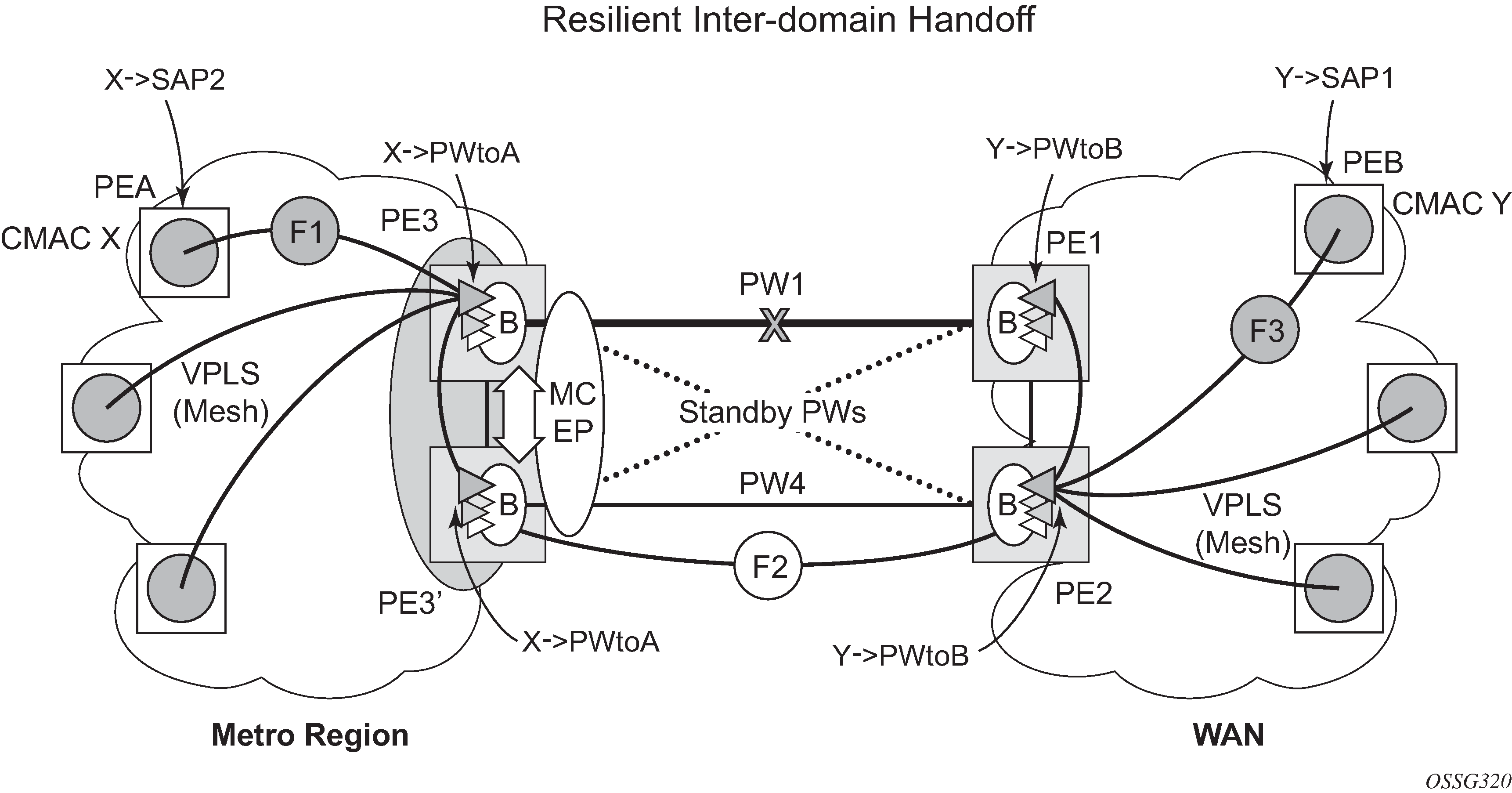
In this example, the MC-EP activates B-VPLS PW4 because of either a link/node failure or because of an MC-EP selection re-run that affected the previously active PW1. As a result, the endpoint on PE3 containing PW1 goes down.
The following steps apply:
PE3 sends, in the local I-VPLS context, an LDP flush-all-from-me message (marked with F1) to PEA and to the other regular VPLS PEs, including PE3. The following command enables this behavior on a per I-VPLS basis: config>service>vpls ivpls>send-flush-on-bvpls-failure.
Result: PEA, PE3, and the other local VPLS PEs in the metro clear the VPLS FDB entries associated with PW to PE3.
PE3 clears the entries associated with PW1 and sends, in the B-VPLS context, an LDP flush-all-but-mine message (marked with F2) toward PE2 on the active PW4.
Result: PE2 clears the B-VPLS FDB entries not associated with PW4.
PE2 propagates the MAC flush-all-but-mine (marked with F3) from B-VPLS in the related I-VPLS contexts toward all participating VPLS PEs; for example, in the blue I-VPLS to PEB, PE1. It also clears all the C-MAC entries associated with I-VPLS pseudowires.
The following command enables this behavior on a per I-VPLS basis:
config>service>vpls ivpls>propagate-mac-flush-from-bvpls
Result: PEB, PE1, and the other local VPLS PEs in the WAN clear the VPLS FDB entries associated with PW to PE2.
This command does not control the propagation in the related I-VPLS of the B-VPLS LDP MAC flush containing a PBB TLV (B-MAC and ISID list).
Similar to regular VPLS, LDP signaling of the MAC flush follows the active topology; for example, no MAC flush is generated on standby pseudowires.
Other failure scenarios are addressed using the same or a subset of the above steps:
If the pseudowire (PW2) in the same endpoint with PW1 becomes active instead of PW4, there is no MAC flush of F1 type.
If the pseudowire (PW3) in the same endpoint becomes active instead of PW4, the same procedure applies.
For an SC/MC endpoint configured in a B-VPLS, failure/deactivation of the active pseudowire member always generates a local MAC flush of all the B-MAC associated with the pseudowire. It never generates a MAC move to the newly active pseudowire even if the endpoint stays up. That is because in SC-EP/MC-EP topology, the remote PE may be the terminating PBB PE and may not be able to reach the B-MAC of the other remote PE. Therefore, connectivity between them exists only over the regular VPLS mesh.
For the same reasons, Nokia recommends that static B-MAC not be used on SC/MC endpoints.