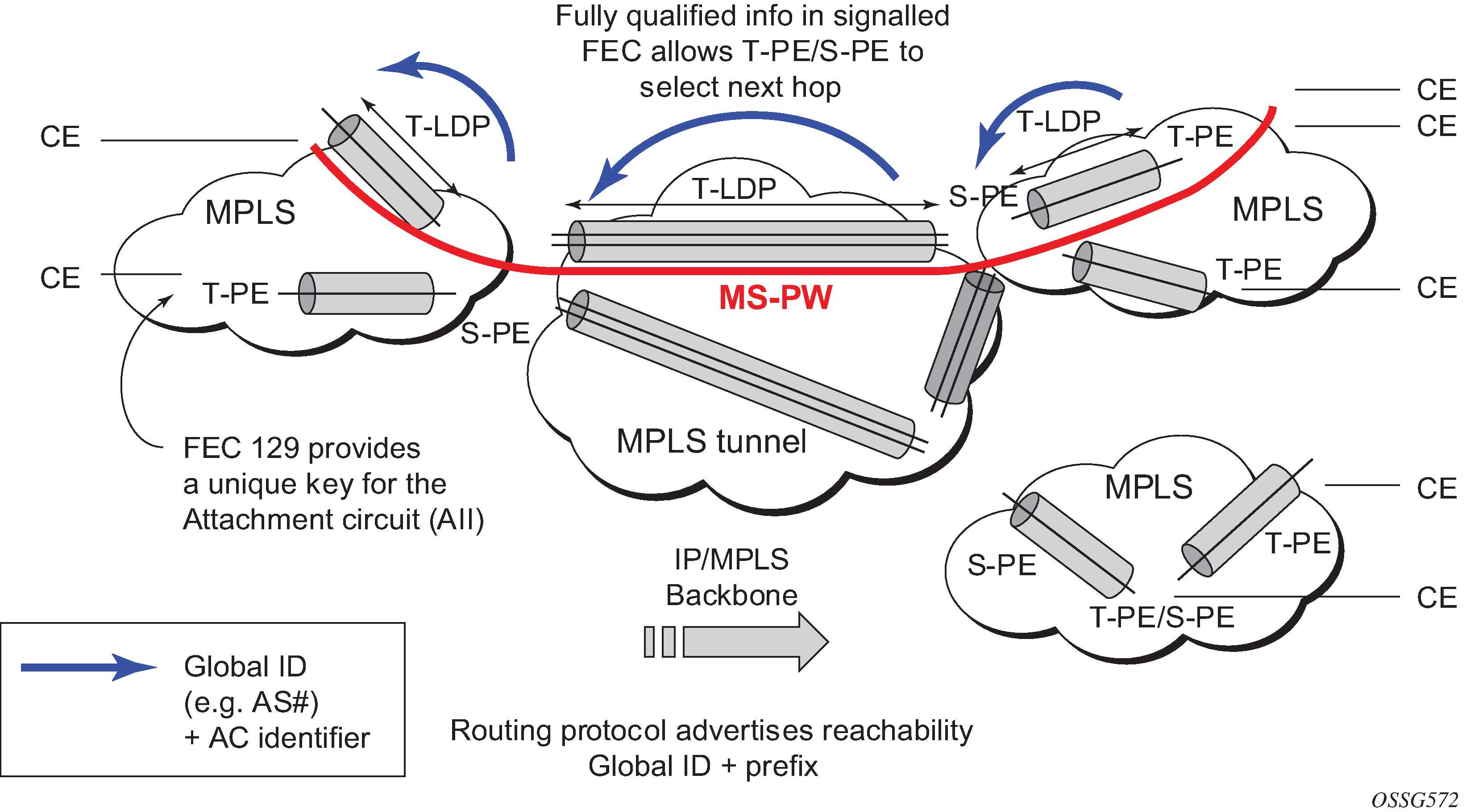
Dynamic Multi-Segment Pseudowire Routing (Dynamic MS-PWs) enable a complete multi-segment pseudowire to be established, while only requiring per-pseudowire configuration on the T-PEs. No per-pseudowire configuration is required on the S-PEs. End-to-end signaling of the MS-PW is achieved using T-LDP, while multi-protocol BGP is used to advertise the T-PEs, allowing dynamic routing of the MS-PW through the intervening network of S-PEs. Dynamic multi-segment pseudowires are described in the IETF Draft draft-ietf-pwe3-dynamic-ms-pw-13.txt.
Figure 1 shows the operation of dynamic MS-PWs.
The FEC 129 AII Type 2 structure depicted in Figure 2 is used to identify each individual pseudowire endpoint:
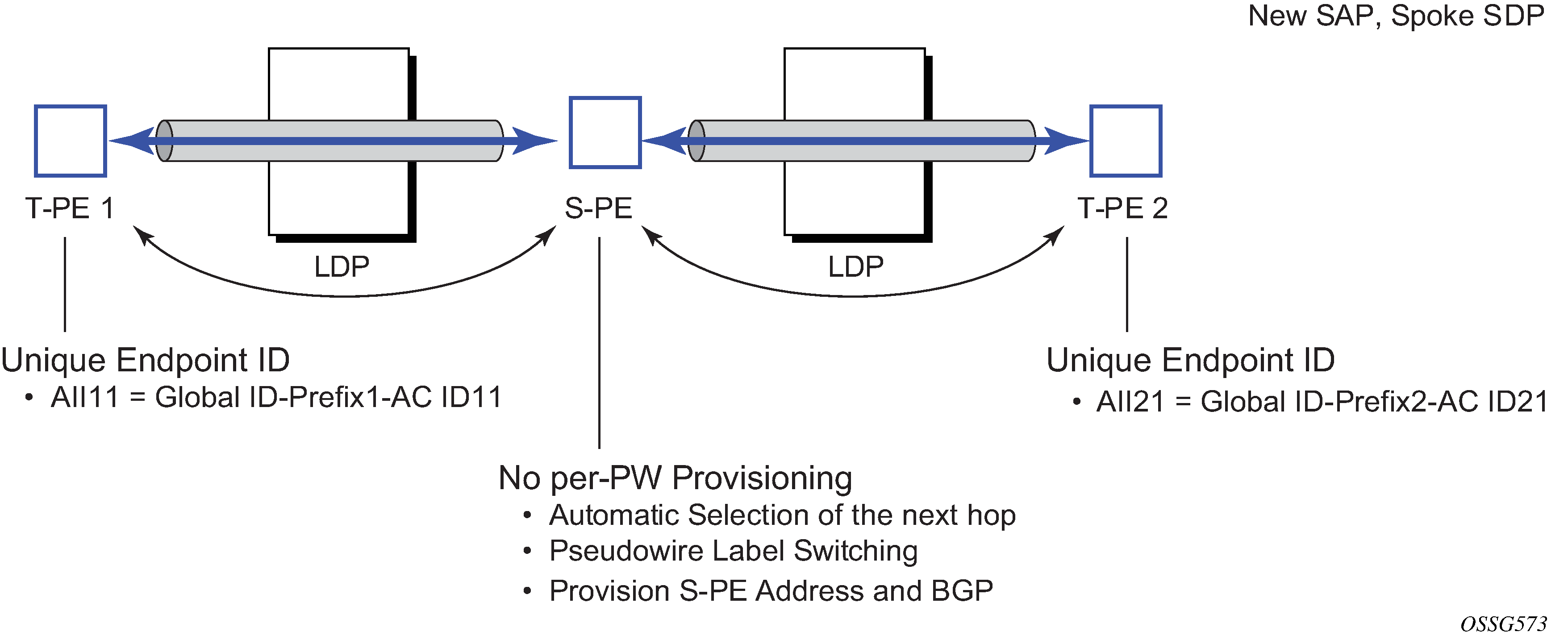
A 4-byte global-id followed by a 4-byte prefix and a 4-byte attachment circuit ID are used to provide for hierarchical, independent allocation of addresses on a per-service provider network basis. The first 8 bytes (global-id + prefix) may be used to identify each individual T-PE or S-PE as a loopback Layer 2 address.
The AII type is mapped into the MS-PW BGP NLRI (a BGP AFI of L2VPN, and SAFI for network layer reachability information for dynamic MS-PWs). As soon as a new T- PE is configured with a local prefix address of global id: prefix, pseudowire routing proceeds to advertise this new address to all the other T- PEs and S-PEs in the network, as depicted in Figure 3.
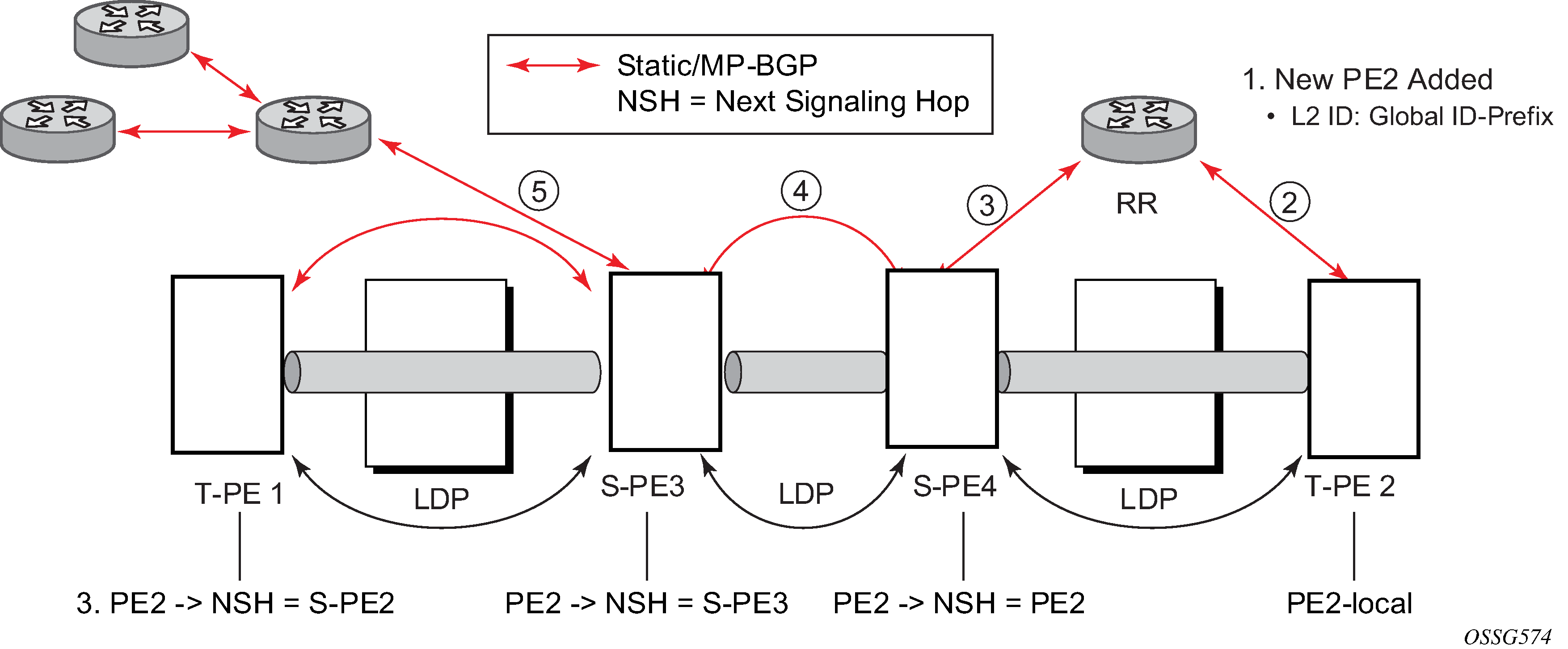
In step 1 of Figure 3, a new T-PE (T-PE2) is configured with a local prefix.
Next, in steps 2 to 5, MP-BGP uses the NLRI for the MS-PW routing SAFI to advertise the location of the new T-PE to all the other PEs in the network. Alternatively, static routes may be configured on a per T-PE/S-PE basis to accommodate non-BGP PEs in the solution.
As a result, pseudowire routing tables for all the S-PEs and remote T-PEs are populated with the next hop to be used to reach T-PE2.
VLL services can then be established, as illustrated in Figure 4.
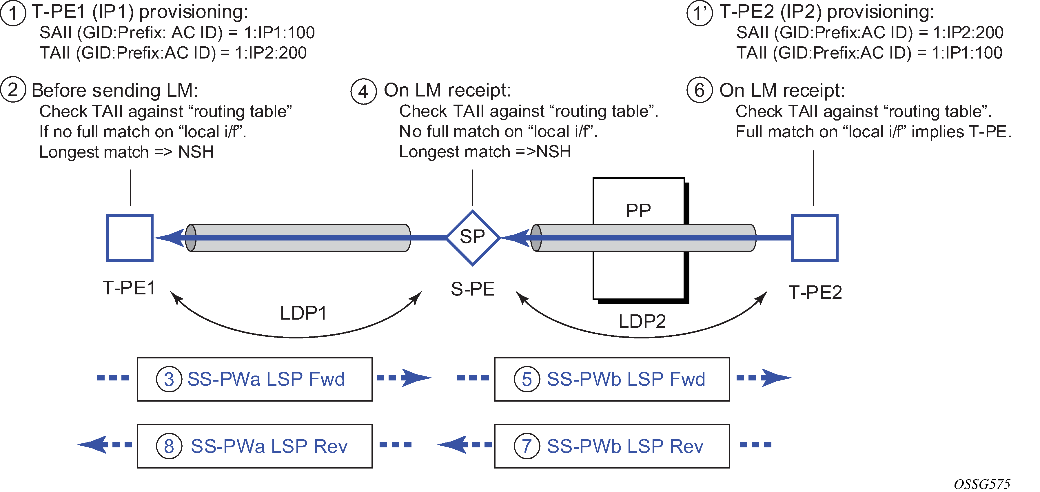
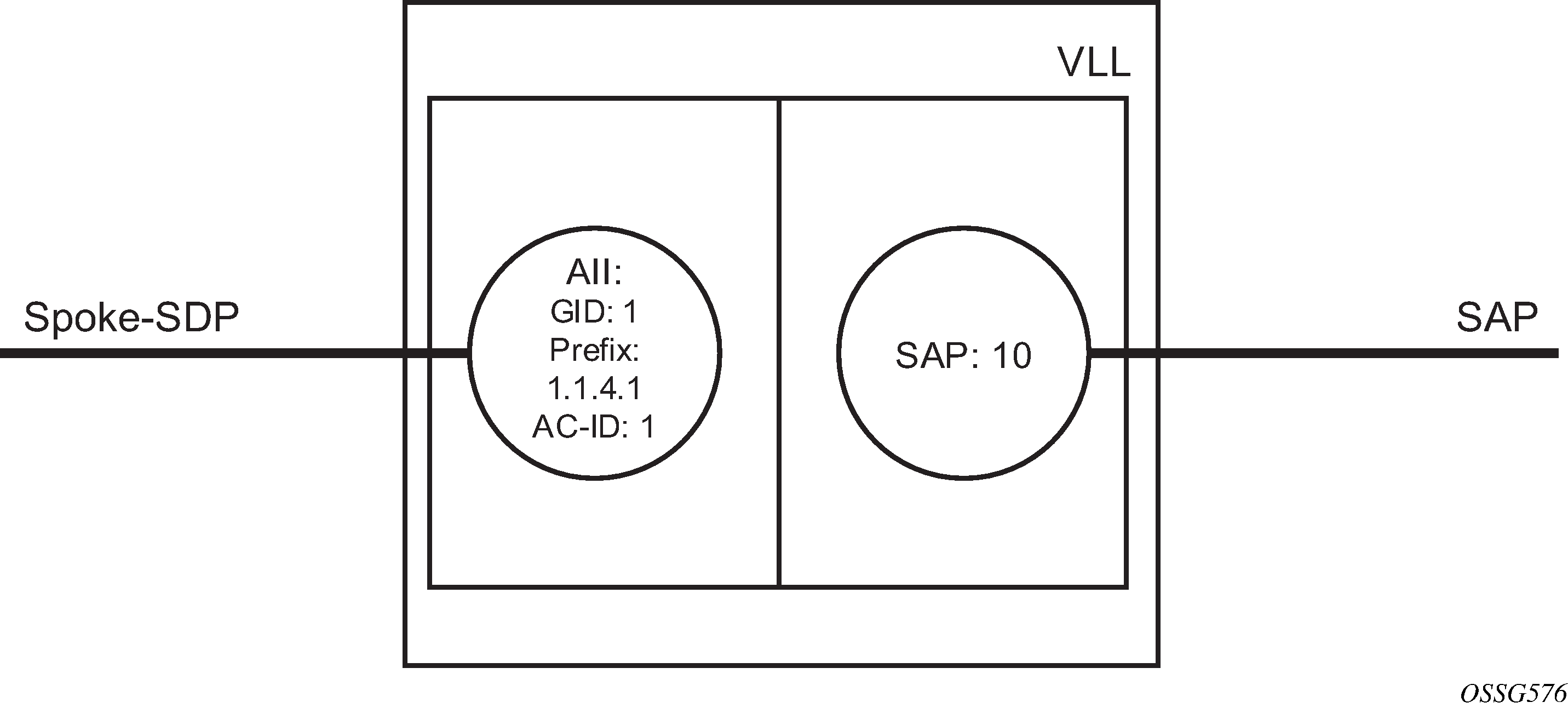
In step 1 and 1' of Figure 4 the T-PEs are configured with the local and remote endpoint information: source AII (SAII) and Target AII (TAII). On the router, the AIIs are locally configured for each spoke-SDP, according to the model shown in Figure 5. Therefore the router provides for a flexible mapping of the AII to SAP. That is, the values used for the AII are through local configuration, and it is the context of the spoke-SDP that binds it to a specific SAP.
Before T-LDP signaling starts, the two T-PEs decide on an active and passive relationship using the highest AII (comparing the configured SAII and TAII) or the configured precedence. Next, the active T-PE (in the IETF draft, this is referred to as the source T-PE or ST-PE) checks the PW routing table to determine the next signaling hop for the configured TAII using the longest match between the TAII and the entries in the PW routing table.
This signaling hop is then used to choose the T-LDP session to the chosen next-hop S-PE. Signaling proceeds through each subsequent S-PE using similar matching procedures to determine the next signaling hop. Otherwise, if a subsequent S-PE does not support dynamic MS-PW routing, so uses a statically configured PW segment, the signaling of individual segments follows the procedures already implemented in the PW Switching feature.
BGP can install a PW AII route in the PW routing table with ECMP next-hops. However, when LDP needs to signal a PW with matching TAII, it chooses only one next-hop from the available ECMP next-hops. PW routing supports up to 4 ECMP paths for each destination.
The signaling of the forward path ends when the PE matches the TAII in the label mapping message with the SAII of a spoke-SDP bound to a local SAP. The signaling in the reverse direction can now be initiated, which follows the entries installed in the forward path. The PW routing tables are not consulted for the reverse path. This ensures that the reverse direction of the PW follows exactly the same set of S-PEs as the forward direction.
This solution can be used in either a MAN-WAN environment or in an Inter-AS/Inter-Provider environment as depicted in Figure 6.
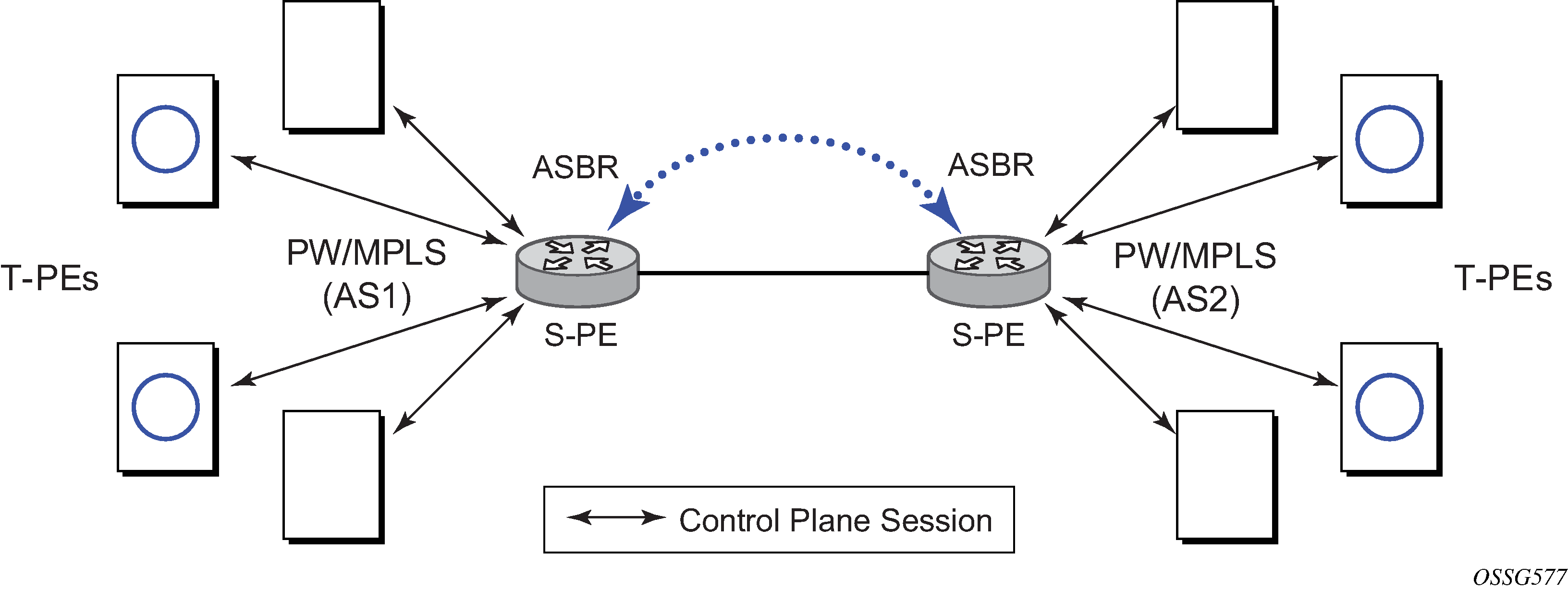
Data plane forwarding at the S-PEs uses pseudowire service label switching, as per the pseudowire switching feature.