The PBB-VPLS solution can be used to improve scalability of the solution and to reduce convergence time. If PBB-VPLS is deployed starting at the edge PEs, the gateway PEs contain only B-VPLS instances. The MC-EP procedures described for regular VPLS apply.
PBB-VPLS can also be enabled just on the gateway MC-EP PEs, as shown in Figure 1.
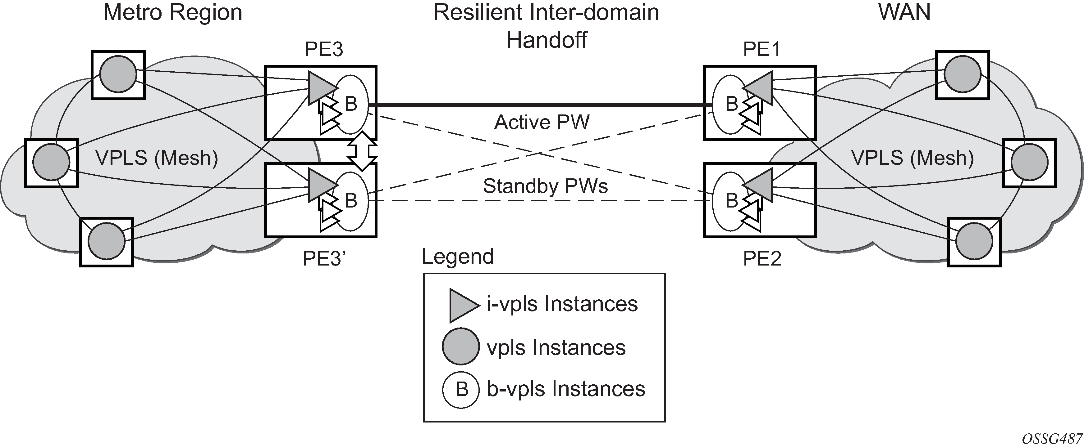
Multiple I-VPLS instances may be used to represent in the gateway PEs the customer VPLS instances using the PBB-VPLS M:1 model described in the PBB section. A backbone VPLS (B-VPLS) is used in this example to administer the resiliency for all customer VPLS instances at the domain borders. Just one MC-EP is required to be configured in the B-VPLS to address hundreds or even thousands of customer VPLS instances. If load balancing is required, multiple B-VPLS instances may be used to ensure even distribution of the customers across all the pseudowires interconnecting the two domains. In this example, four B-VPLSs are able to load share the customers across all four possible pseudowire paths.
The use of MC-EP with B-VPLS is strictly limited to cases where VPLS mesh exists on both sides of a B-VPLS. For example, active/standby pseudowires resiliency in the I-VPLS context where PE3 and PE3’ are PE-rs cannot be used because there is no way to synchronize the active/standby selection between the two domains.
For a similar reason, MC-LAG resiliency in the I-VPLS context on the gateway PEs participating in the MC-EP (PE3 and PE3’) should not be used.
For the PBB topology in Figure 1, block-on-mesh-failure in the I-VPLS domain does not have any effect on the B-VPLS MC-EP side. That is because mesh failure in one I-VPLS should not affect other I-VPLSs sharing the same B-VPLS.