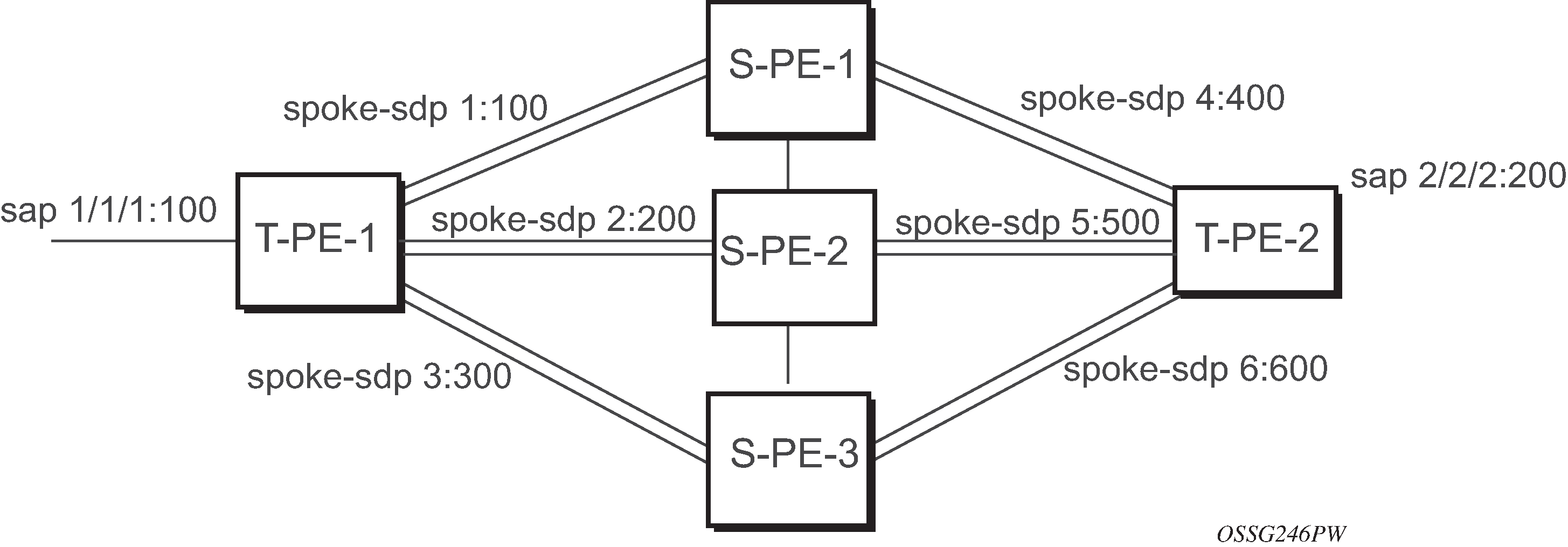
Figure 1 displays VLL resilience for a switched pseudowire path example. An example configuration follows.
Figure 1. VLL Resilience with Pseudowire Switching
T-PE-1
configure service epipe 1
   endpoint X
   exit
   endpoint Y
   revert-time 100
   standby-signaling-master
   exit
   sap 1/1/1:100 endpoint X
   spoke-sdp 1:100 endpoint Y
      precedence primary
   spoke-sdp 2:200 endpoint Y
      precedence 1
   spoke-sdp 3:300 endpoint Y
      precedence 1

T-PE-2
configure service epipe 1
   endpoint X
   exit
   endpoint Y
   revert-time 100
   standby-signaling-slave
   exit
   sap 2/2/2:200 endpoint X
   spoke-sdp 4:400 endpoint Y
      precedence primary
   spoke-sdp 5:500 endpoint Y
      precedence 1
   spoke-sdp 6:600 endpoint Y
      precedence 1
VC switching indicates a VC cross-connect so that the service manager does not signal the VC label mapping immediately but puts S-PE-1 into passive mode, as follows:
configure service epipe 1 vc-switching
   spoke-sdp 1:100
   spoke-sdp 4:400