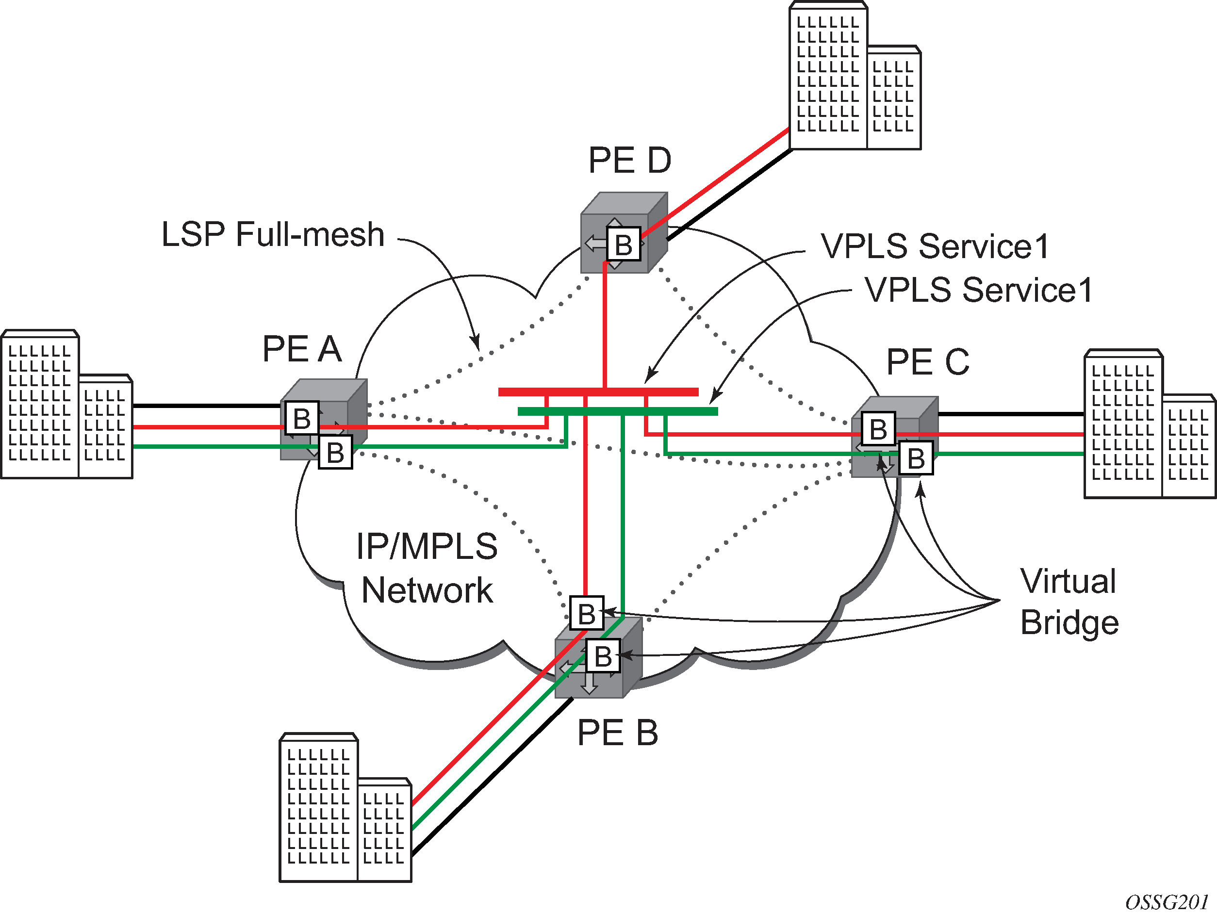
This section provides an example of VPLS processing of a customer packet sent across the network from site A, which is connected to PE Router A, to site B, which is connected to PE Router C (see Figure 1).
PE Router A (see Figure 2)
Service packets arriving at PE Router A are associated with a VPLS service instance based on the combination of the physical port and the IEEE 802.1Q tag (VLAN ID) in the packet.
Figure 2. Access Port Ingress Packet Format and Lookup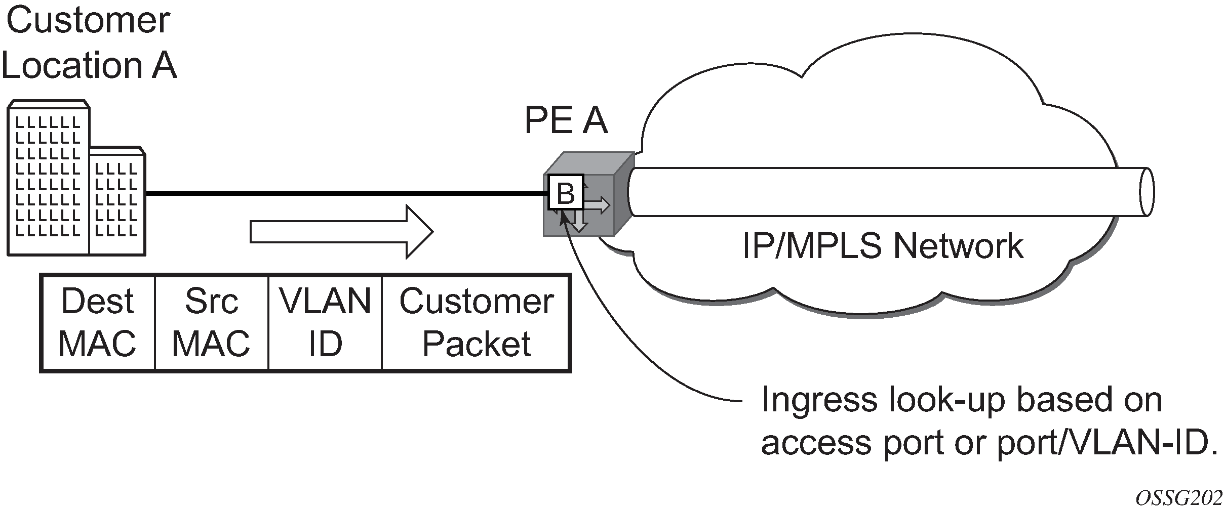
PE Router A learns the source MAC address in the packet and creates an entry in the FDB table that associates the MAC address with the service access point (SAP) on which it was received.
The destination MAC address in the packet is looked up in the FDB table for the VPLS instance. There are two possibilities: either the destination MAC address has already been learned (known MAC address) or the destination MAC address is not yet learned (unknown MAC address).
For a known MAC address see Figure 3.
If the destination MAC address has already been learned by PE Router A, an existing entry in the FDB table identifies the far-end PE router and the service VC-label (inner label) to be used before sending the packet to far-end PE Router C.
PE Router A chooses a transport LSP to send the customer packets to PE Router C. The customer packet is sent on this LSP after the IEEE 802.1Q tag is stripped and the service VC-label (inner label) and the transport label (outer label) are added to the packet.
For an unknown MAC address see Figure 3.
If the destination MAC address has not been learned, PE Router A floods the packet to both PE Router B and PE Router C that are participating in the service by using the VC-labels that each PE Router previously added for the VPLS instance. The packet is not sent to PE Router D because this VPLS service does not exist on that PE router.
Figure 3. Network Port Egress Packet Format and Flooding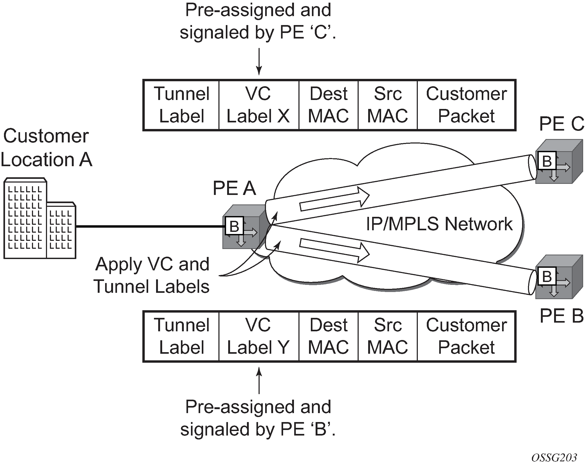
Core Router Switching
All the core routers (‟P” routers in IETF nomenclature) between PE Router A and PE Router B and PE Router C are Label Switch Routers (LSRs) that switch the packet based on the transport (outer) label of the packet until the packet arrives at the far-end PE Router. All core routers are unaware that this traffic is associated with a VPLS service.
PE Router C
PE Router C strips the transport label of the received packet to reveal the inner VC-label. The VC-label identifies the VPLS service instance to which the packet belongs.
PE Router C learns the source MAC address in the packet and creates an entry in the FDB table that associates the MAC address with PE Router A, and the VC-label that PE Router A added for the VPLS service on which the packet was received.
The destination MAC address in the packet is looked up in the FDB table for the VPLS instance. Again, there are two possibilities: either the destination MAC address has already been learned (known MAC address) or the destination MAC address has not been learned on the access side of PE Router C (unknown MAC address).
For a known MAC address see Figure 4.
If the destination MAC address has been learned by PE Router C, an existing entry in the FDB table identifies the local access port and the IEEE 802.1Q tag to be added before sending the packet to customer Location C. The egress Q tag may be different than the ingress Q tag.
