The recursive opaque type used for Inter-AS Option B is the Recursive Opaque (VPN Type), shown as opaque type 8 in Table 1.
Inter-AS Option B Support for NG-MVPN
Inter-AS Option B requires additional processing on ASBR routers and recursive FEC encoding than that of Inter-AS Option A. Because BGP adjacency is not e2e, ASBRs must cache and use a PMSI route to build the tree. For that, mLDP recursive FEC must carry RD information—thus, VPN recursive FEC is required (opaque type 8).
In Inter-AS Option B, the PEs in two different ASs do not have their system IP address in the RTM. As such, for NG-MVPN, a recursive opaque value in mLDP FEC is required to signal the LSP to the first ASBR in the local AS path.
Because the system IPs of the peer PEs (Root-1 and Root-2) are not installed on the local PE (leaf), it is possible to have two PEs in different ASs with same system IP address, as shown in Figure 1. However, SR OS does not support this topology. The system IP address of all nodes (root or leaf) in different ASs must be unique.
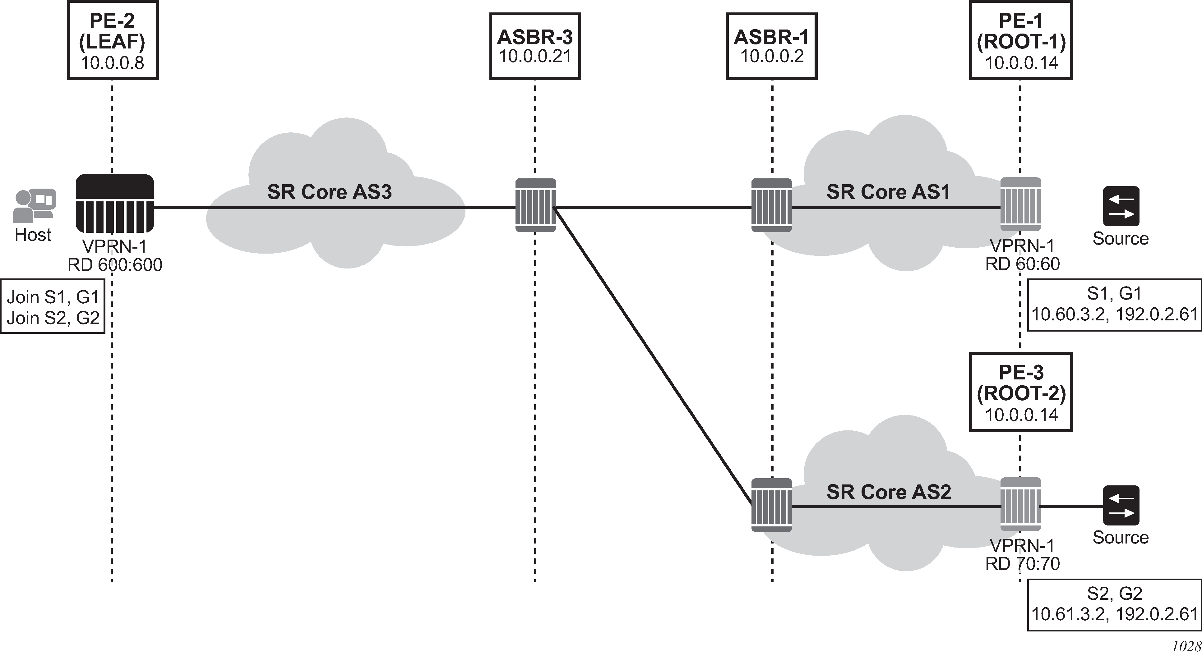
For inter-AS Option B and NG-MVPN, SR OS as a leaf does not support multiple roots in multiple ASs with the same system IP and different RDs; however, the first root that is advertised to an SR OS leaf will be used by PIM to generate an MLDP tunnel to this actual root. Any dynamic behavior after this point, such as removal of the root and its replacement by a second root in a different AS, is not supported and the SR OS behavior is nondeterministic.
I-PMSI and S-PMSI Establishment
I-PMSI and S-PMSI functionality follows RFC 6513 section 8.1.1 and RFC 6512 sections 3.1 and 3.2.1. For routing, the same rules as for GRT d-mLDP use case apply, but the VRR Route Import External community now encodes the VRF instance in the local administrator field.
Option B uses an outer opaque of type 8 and inter opaque of type 1 (see Table 1).
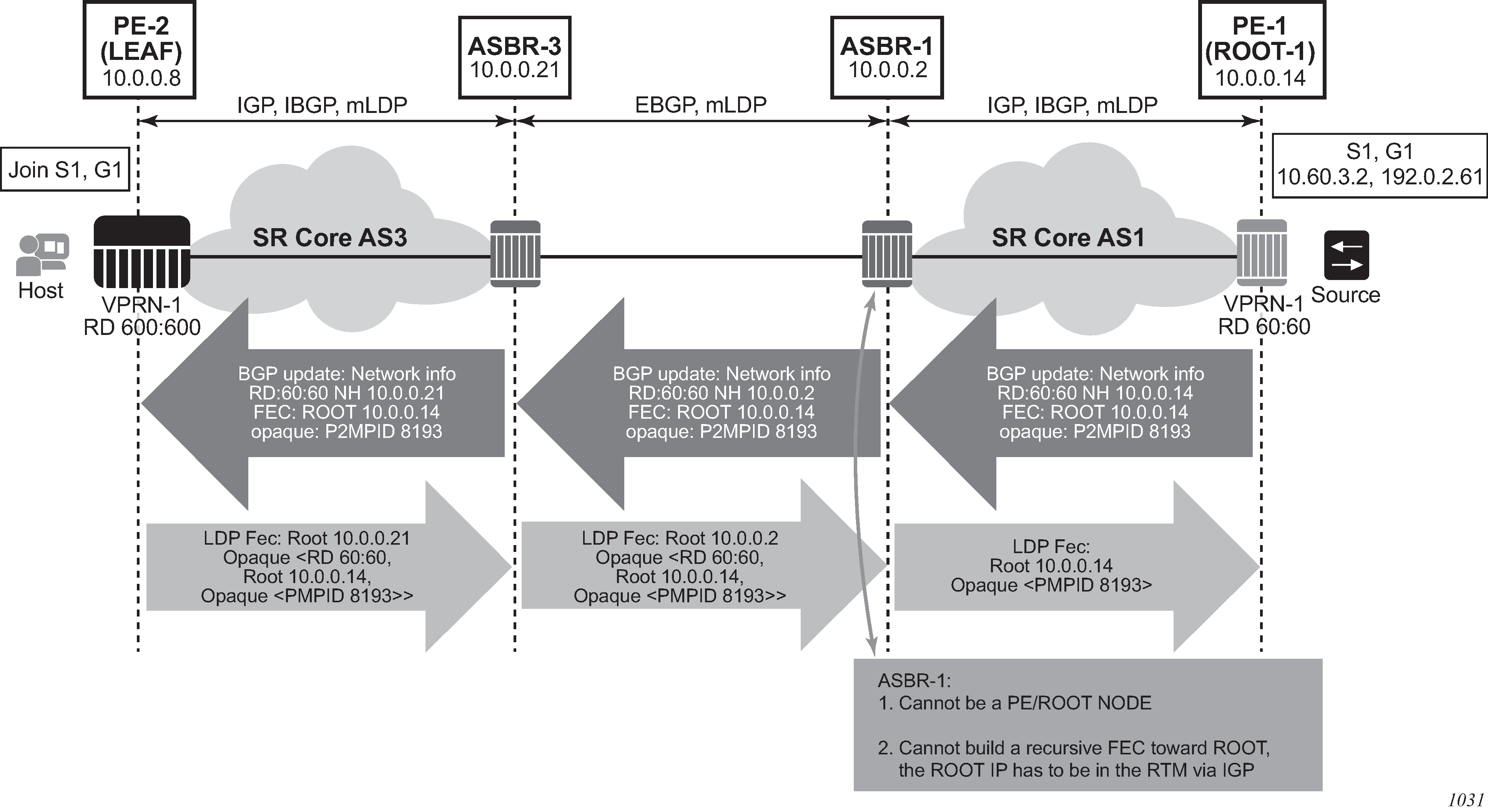
Figure 2 depicts the processing required for I-PMSI and S-PMSI Inter-AS establishment.
For non-segmented mLDP trees, A-D procedures follow those of the Intra-AS model, with the exception that NO EXPORT community must be excluded; LSP FEC includes mLDP VPN-recursive FEC.
For I-PMSI on Inter-AS Option B:
A-D routes must be installed by ASBRs and next-hop information is changed as the routes are propagated, as shown in Figure 2.
PMSI A-D routes are used to provide inter-domain connectivity on remote ASBRs.
On a receipt of an Intra-AS PMSI A-D route, PE2 resolves PE1’s address (next-hop in PMSI route) to a labeled BGP route with a next-hop of ASBR3, because PE1 (Root-1) is not known via IGP. Because ASBR3 is not the originator of the PMSI route, PE2 sources an mLDP VPN recursive FEC with a root node of ASBR3, and an opaque value containing the information advertised by Root-1 (PE-1) in the PMSI A-D route, shown below, and forwards the FEC to ASBR 3 using IGP.
PE-2 LEAF FEC: (Root ASBR3, Opaque value {Root: ROOT-1, RD 60:60, Opaque Value: P2MPLSP-ID xx}}
When the mLDP VPN-recursive FEC arrives at ASBR3, it notes that it is the identified root node, and that the opaque value is a VPN-recursive opaque value. Because Root-1 PE1 Is not known via IGP, ASBR3 resolves the root node of the VPN-Recursive FEC using PMSI A-D (I or S) matching the information in the VPN-recursive FEC (the originator being PE1 (Root-1), RD being 60:60, and P2MP LSP ID xx). This yields ASBR1 as next hop. ASBR3 creates a new mLDP FEC element with a root node of ASBR1, and an opaque value being the received recursive opaque value, as shown below. ASBR then forwards the FEC using IGP.
ASBR-3 FEC: {Root ASBR 1, Opaque Value {Root: ROOT-1, RD 60:60, Opaque Value: P2MPLSP-ID xx}}
When the mLDP FEC arrives at ASBR1, it notes that it is the root node and that the opaque value is a VPN-recursive opaque value. As PE1’s ROOT-1 address is known to ASBR1 through the IGP, no further recursion is required. Regular processing begins, using received Opaque mLDP FEC information.
ASBR-1 FEC: {Root: ROOT-1, Opaque Value: P2MP LSP-ID xx
VPN-Recursive FEC carries P2MPLSP ID. The P2MPLSP ID is used in addition to PE RD and Root to select a route to the mLDP root using the correct I-PMSI or S-PMSI route.
The functionality as described above for I-PMSI applies also to S-PMSI and (C-*, C-*) S-PMSI.
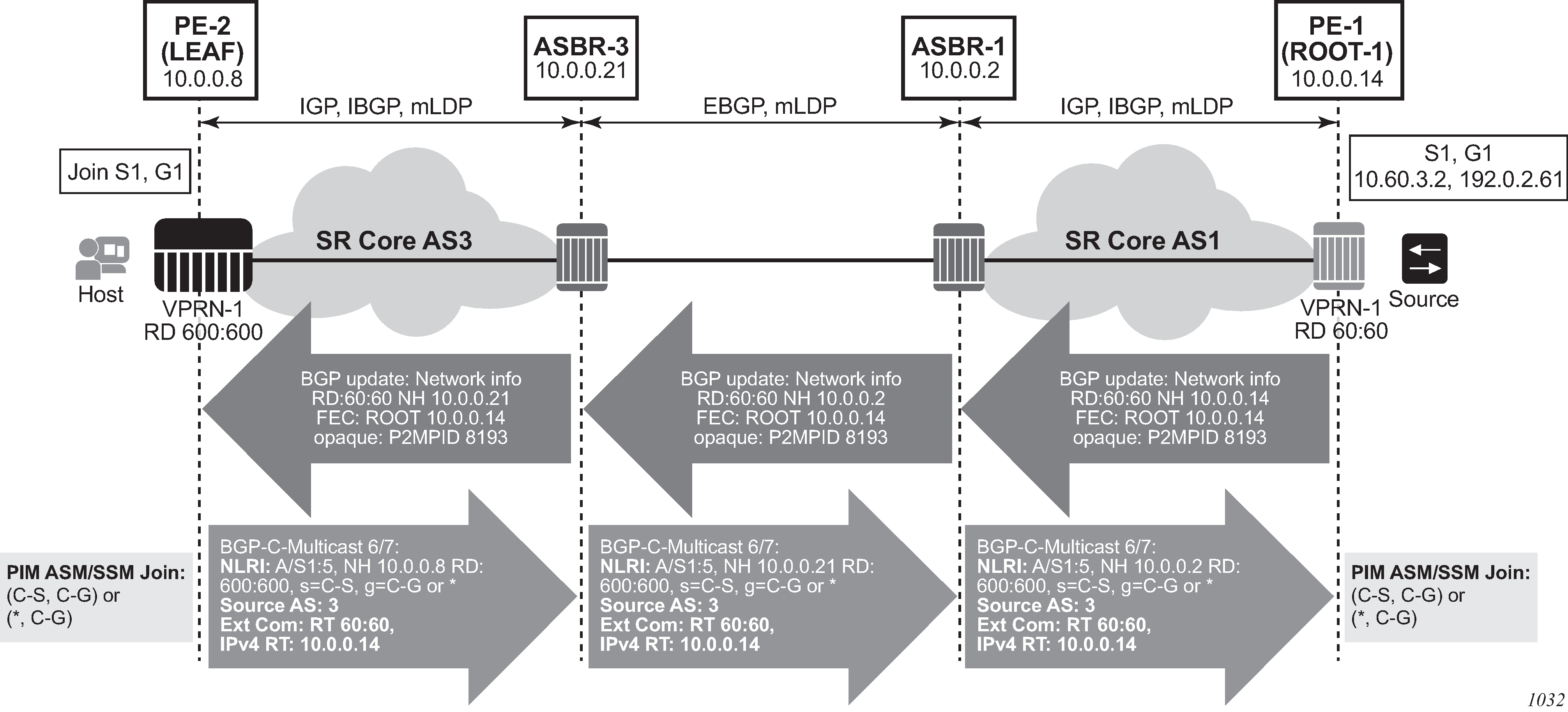
C-multicast Route Processing
C-multicast route processing functionality follows RFC 6513 section 8.1.2 (BGP used for route exchange). The processing is analogous to BGP Unicast VPN route exchange described in Figure 1 and Figure 2. Figure 3 shows C-multicast route processing with non-segmented mLDP PMSI details.