When a MEP at a server layer (such as a link layer with respect to a specified LSP) detects a failure, the server MEP notifies a co-located client layer of the condition. The client layer then generates Alarm Indication Signal (AIS) packets downstream in the client layer. These fault OAM messages are generated by intermediate nodes where a client LSP is switched, as per RFC 6427. This means that AIS packets are only inserted at an LSP MIP. AIS is used by the receiving MEP to suppress client layer traps caused by the upstream server layer failure; for example, if BFD CC is running on the LSP, then AIS suppresses the generation of multiple traps because of loss of CC.
Figure 1 illustrates an example of the operation of AIS in MPLS-TP.
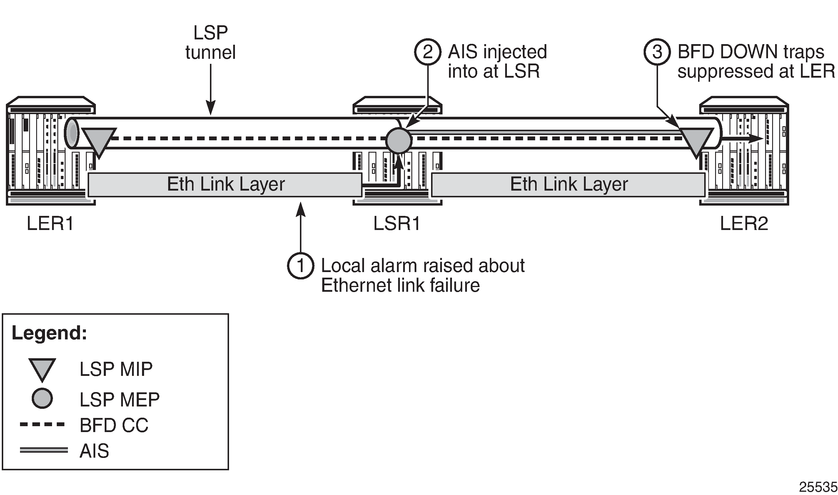
In the example, a failure of the Ethernet link layer between PE1 and LSR1 is detected at LSR1, which raises a local trap. LSPs transiting the LSR may be running CC OAM, such as BFD, and have AIS packets injected into them at LSR1. These AIS messages are received by the corresponding downstream MEP and processed. The failure of the Ethernet link between PE1 and LSR1 means that CC OAM on the LSPs is not received by the MEPs at PE2. Normally, this would cause multiple traps to be raised at PE2, but the reception of AIS causes PE2 to suppress the local generation of traps related to the failed LSP.
For traps to be suppressed successfully, the AIS message must arrive and be processed at the far-end PE or LER in sufficient time for the initial alarm to be suppressed. Therefore, the router implements a 2.5 secs hold-down timer for such traps on MPLS-TP LSPs.
Fault management for MPLS-TP, including AIS, is specified in RFC 6427.
The router supports:
receiving and processing of AIS messages at LSP MEPs (at the LER)
generation of AIS messages at LSP MIPs (at the LSR) in response to a failure of the ingress link
suppression of SNMP traps indicating changes in the state of a BFD session, which result from the failure of the LSP data path upstream of a receiving LER; these traps would otherwise be sent to the 5620 SAM
suppression of any BFD state machine Up/Down changes that occur while AIS is being received; there is no buffering or storage of state machine changes that occur during this period. This suppression only applies to Up/Down state change traps; other traps that would be expected are observed as normal.
inclusion of the Link Down Indication (LDI) in an AIS message. This triggers a switchover of LSP linear protection if used on the LSP.
insertion of AIS in the downstream direction of the transit path if a unidirectional fault is detected at an LSR. This suppresses CC traps at the downstream LER. However, the BFD session still goes down, causing RDI to be sent upstream in BFD, which causes an alarm at the upstream LER.